• Skip to main content
  • Skip to primary sidebar

Homemade Circuit Projects

Get free circuit help 24/7

New Projects | Privacy Policy | About us | Contact | Disclaimer | Copyright | Videos 

You are here: Home / Power Supply Circuits / 5 V to 10 V Converter for TTL Circuits

5 V to 10 V Converter for TTL Circuits

Last Updated on April 19, 2020 by Swagatam Leave a Comment

The post explains a simple 5 V to 10 V converter circuit which can be used in TTL circuits where only 5 V is available and converting this 5 V to 10 V can be extremely useful for operating an adjacent circuit which may require a supply of around 9 V or 12 V.

This voltage doubler circuit can be very handy in circuits which are designed to work with only a 5 V supply voltage, and where a larger voltage is necessary for a different circuit stage.

Circuit Description

Figure exhibits the fundamental design, that makes use of 3 gates from the IC 7437 quad two-input NAND buffer IC.

caution electricity can be dangerous

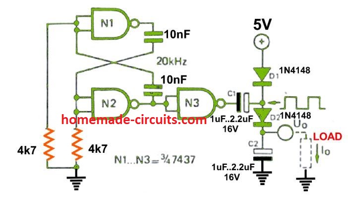
Gates N1 and N2 are joined to form a 20 kHz astable multivibrator, and the N2 output runs N3, which behaves like a buffer between the astable and the voltage doubler stages. Once the N3 output is low C1 starts charging up via D1 and N3 to around + 4.4 V.

As soon as the N3 output turns high the voltage over the C1 positive pin becomes 9 V, causing C1 to discharge by means of D2 into C2. In case no current is pulled from C2 it will continue to charge until the voltage across it reaches +8.5 V.

On the other hand, in case any considerable current is utilized by a load, might cause the output voltage to drop rapidly.

Improving Voltage Regulation

A much improved output voltage regulation, could be achieved by incorporating a push-pull design as shown in the following figure.

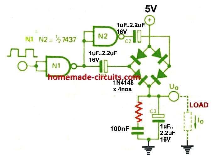
This improved 5 V to 10 V converter circuit is driven by a suitable astable square wave source such as from the output of N3 in our previous diagram.

When the N1 output turns low and C1 is in the charging mode, the N2 output becomes high and C2 begins discharging into C3, and vice versa.

Given that C3 is subjected to a continuous charging we find the output voltage regulation much enhanced and stronger than any ordinary voltage doubler variant.
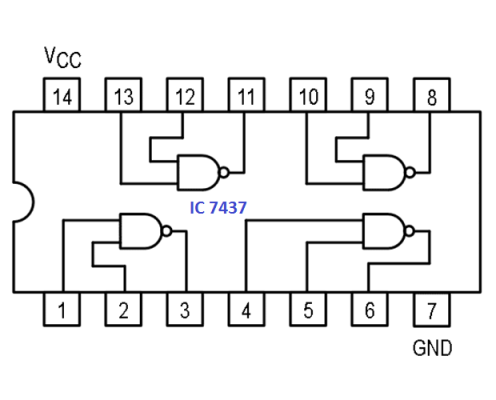
IC 7437 pinout

The following image shows the internal details and pinout configuration of the IC 7437

You'll also like:

  • 1.  Over Current Cut-off Power Supply Using Arduino
  • 2.  Voltage Regulator Circuits using Transistor and Zener Diode
  • 3.  High Current Adjustable Switching Power Supply Circuit using L296 IC
  • 4.  Higher Variable Output Voltage from IC 7812
  • 5.  How to Modify SMPS for Adjustable Current and Voltage Output
  • 6.  Fuel Cells [How they Work]

About Swagatam

I am an electronic engineer (dipIETE ), hobbyist, inventor, schematic/PCB designer, manufacturer. I am also the founder of the website: https://www.homemade-circuits.com/, where I love sharing my innovative circuit ideas and tutorials.
If you have any circuit related query, you may interact through comments, I'll be most happy to help!

Have Questions? Please Comment below to Solve your Queries! Comments must be Related to the above Topic!!

Subscribe
Notify of
0 Comments
Inline Feedbacks
View all comments


Primary Sidebar

Categories

  • 3-Phase Power (15)
  • 324 IC Circuits (19)
  • 4017 IC Circuits (52)
  • 4060 IC Circuits (26)
  • 555 IC Circuits (99)
  • 741 IC Circuits (20)
  • Arduino Engineering Projects (83)
  • Audio and Amplifier Projects (118)
  • Battery Chargers (83)
  • Car and Motorcycle (96)
  • Datasheets (77)
  • Decorative Lighting (Diwali, Christmas) (33)
  • Electronic Components (101)
  • Electronic Devices and Circuit Theory (36)
  • Electronics Tutorial (120)
  • Fish Aquarium (5)
  • Free Energy (34)
  • Fun Projects (14)
  • GSM Projects (9)
  • Health Related (20)
  • Heater Controllers (30)
  • Home Electrical Circuits (106)
  • How to Articles (20)
  • Incubator Related (6)
  • Industrial Electronics (28)
  • Infrared (IR) (40)
  • Inverter Circuits (98)
  • Laser Projects (12)
  • LED and Light Effect (95)
  • LM317/LM338 (21)
  • LM3915 IC (25)
  • Meters and Testers (67)
  • Mini Projects (152)
  • Motor Controller (67)
  • MPPT (7)
  • Oscillator Circuits (25)
  • PIR (Passive Infrared) (8)
  • Power Electronics (35)
  • Power Supply Circuits (81)
  • Radio Circuits (10)
  • Remote Control (48)
  • Security and Alarm (64)
  • Sensors and Detectors (127)
  • SG3525 IC (5)
  • Simple Circuits (75)
  • SMPS (29)
  • Solar Controllers (62)
  • Timer and Delay Relay (54)
  • TL494 IC (5)
  • Transformerless Power Supply (8)
  • Transmitter Circuits (41)
  • Ultrasonic Projects (16)
  • Water Level Controller (45)

Calculators

  • AWG to Millimeter Converter
  • Battery Back up Time Calculator
  • Capacitance Reactance Calculator
  • IC 555 Astable Calculator
  • IC 555 Monostable Calculator
  • Inductance Calculator
  • LC Resonance Calculator
  • LM317, LM338, LM396 Calculator
  • Ohm’s Law Calculator
  • Phase Angle Phase Shift Calculator
  • Power Factor (PF) Calculator
  • Reactance Calculator
  • Small Signal Transistor(BJT) and Diode Quick Datasheet
  • Transistor Astable Calculator
  • Transistor base Resistor Calculator
  • Voltage Divider Calculator
  • Wire Current Calculator
  • Zener Diode Calculator

© 2023 · Swagatam Innovations

wpDiscuz