In this post I have explained how to design and build a simple power supply circuit right from the basic design to the reasonably sophisticated power supply having extended features.
Power Supply is Indispensable
Whether it's an electronic noob or an expert engineer, all require this indispensable piece of equipment called the power supply unit.
This is because no electronics can run without power, to be precise a low voltage DC power, and a power supply unit is a device which is specifically meant for fulfilling this purpose.
If this equipment is so important, it becomes imperative for all in the field to learn all the nitty-gritties of this important member of the electronic family.
Let's begin and learn how to design a power supply circuit, a simplest one first , probably for the noobs who would find this information extremely useful.
A basic power supply circuit will fundamentally require three main components for providing the intended results.
A transformer, a diode and a capacitor.The transformer is the device which has two sets of windings, one primary and the other one is the secondary.
Mains 220v or 120v is fed to the primary winding which is transferred to the secondary winding to produce a lower induced voltage there.
The low stepped down voltage available at the secondary of the transformer is used for the intended application in electronic circuits, however before this secondary voltage can be used, it needs to be first rectified, meaning the voltage needs to be made into a DC first.
For example if the transfornmer secondary is rated at 12 volts then the acquired 12 volts from the transformer secondary will be a 12 volt AC acros the relevant wires.
Electronic circuit can never work with ACs and therefore this voltage should be transformed into a DC.
A diode is one device which effectively converts an AC to DC, there are three configurations through which basic power supply designs may be configured.
You may also want to learn how to design a bench power supply
Using a single diode:
The most basic and crude form of power supply design is the one which uses a single diode and a capacitor.
Since a single diode will rectify only one half cycle of the AC signal, this type of configuration requires a large output filter capacitor for compensating the above limitation.
A filter capacitor makes sure that after rectification, at the falling or decreasing sections of the resultant DC pattern, where the voltage tends to dip, these sections are filled and topped by the stored energy inside the capacitor.
The above compensation act done by the capacitors stored energy helps to maintain a clean and ripple free DC output which wouldn't be possible just by the diodes alone.
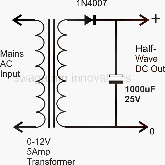
For a single diode power supply design, the transformer's secondary winding just needs to have a single winding with two ends.
However the above configuration cannot be considered an efficient power supply design due to its crude half wave rectification and limited output conditioning capabilities.
Using Two Diodes:
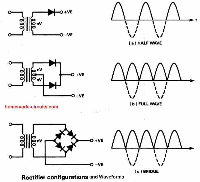
Using a couple of diodes for making a power supply requires a transformer having a center tapped secondary winding. The diagram shows how the diodes are connected to the transformer.
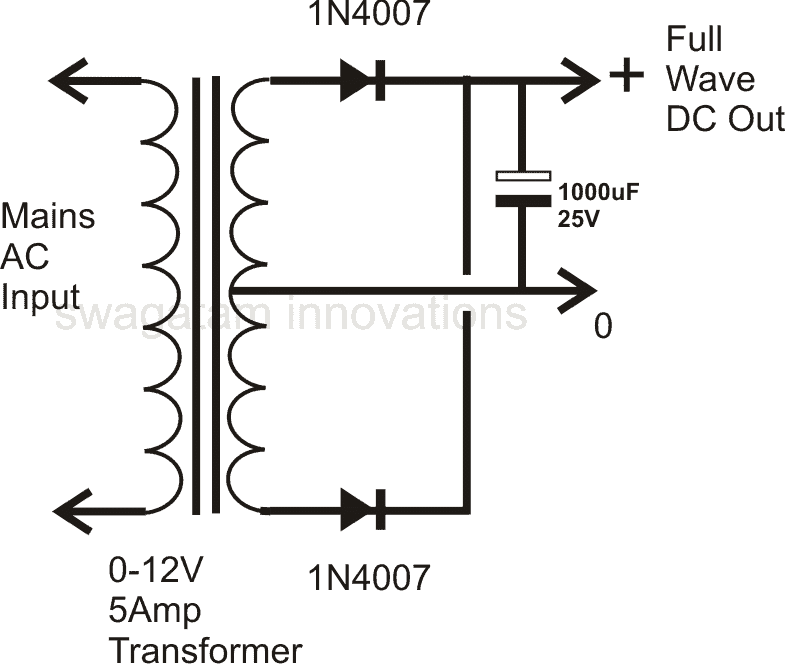
Though, the two diodes work in tandem and tackle both the halves of the AC signal and produce a full wave rectification, the employed method is not efficient, because at any instant only one half winding of the transformer is utilized.
This results in poor core saturation and unnecessary heating of the transformer, making this type of power supply configuration less efficient and an ordinary design.
Using Four Diodes:
It's the best and universally accepted form of power supply configuration as far as the rectification process is concerned.
The clever use of four diodes makes things very simple, only a single secondary winding is all that is required, the core saturation is perfectly optimized resulting in an efficient AC to DC conversion.
The figure shows how a full wave rectified power supply is made using four diodes and a relatively low value filter capacitor.
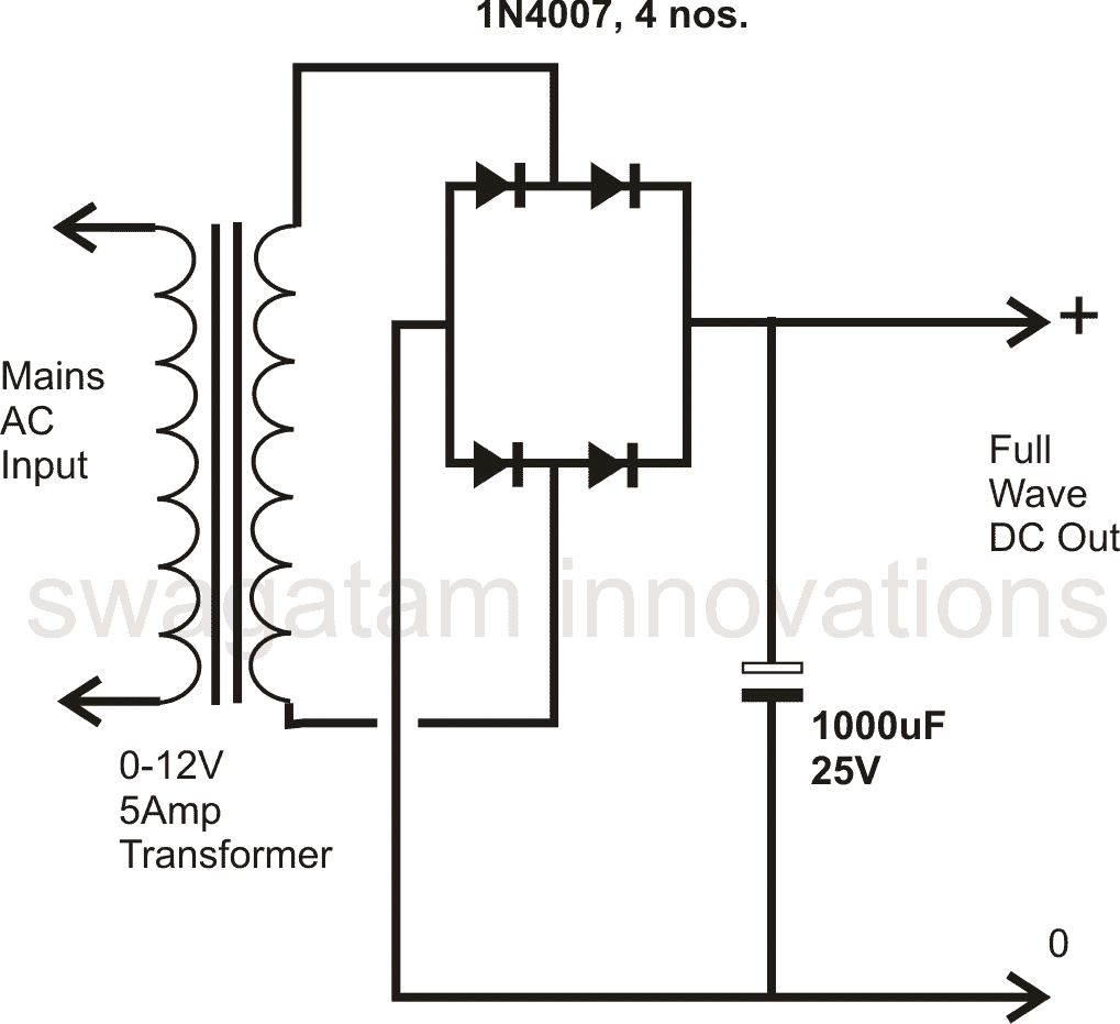
This type of diode configuration is popularly know as the bridge network, you may want to know how to construct a bridge rectifier.
All the above power supply designs provide outputs with ordinary regulation and therefore cannot be considered perfect, these fail to provide ideal DC outputs, and therefore are not desirable for many sophisticated electronic circuits.
Moreover these configurations does not include a variable voltage and current control features.
However the above features may be simply integrated to the above designs, rather with the last full wave power supply configuration through the introduction of a single IC and a few other passive components.
Full Bridge Unregulated Power Supply with Formulas
The diagram below depicts a single rail power supply. The fuse is installed in the live wire path to the transformer for safety.
The live wire is also attached to the transformer's 240V terminal; this section of the primary winding is quite far away from the secondary, increasing the unit's safety.
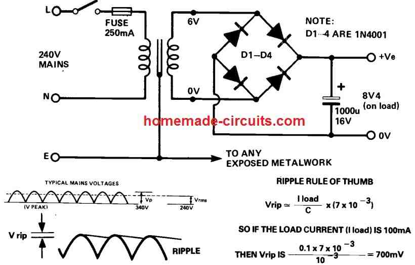
The earth should be linked to any uncovered metal and, if applicable, to the transformer shielding. The voltages mentioned are in volts rms and are AC voltages.
On load, the transformer's output is 6V rms. When the transformer is not in use, the voltage might rise by up to 25%.
The output ripple can be calculated using the following formula:
Vrip ≅ Iload / C [ 7 x 10⁻³ ]
Waveform Images
The output waveform images for the various rectifiers and transformer configurations discussed above, can be seen in the figure below:
Using the IC LM317 or LM338:
The IC LM 317 is a highly versatile device which is normally incorporated with power supplies for obtaining well regulated and variable voltage/current outputs. A few power supply example circuits using this IC
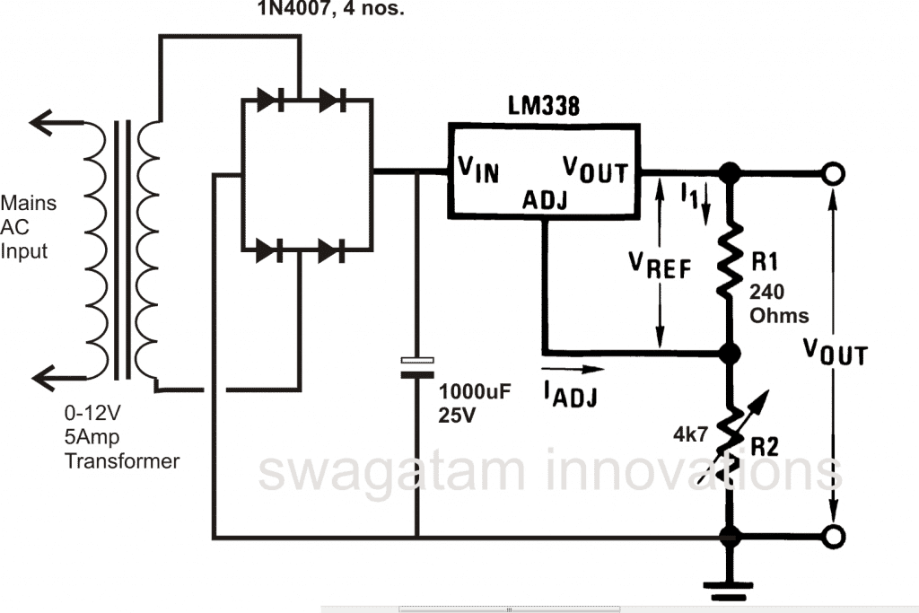
Since the above IC can only support a maximum of 1.5 amps, for greater current outputs another similar device but with higher ratings may be used. The IC LM 338 works exactly like the LM 317 but is capable of handling up to 5 amps of current. A simple design is shown below.
For obtaining fixed voltage levels, 78XX series ICs may be employed with the above explained power supply circuits. The 78XX ICs are comprehensively explained for your refernce
Nowadays transformerless SMPS power supplies are becoming the favorites among the users, due to their high efficiency, high power delivering features at amazingly compact sizes.
Though building an SMPS power supply circuit at home is surely not for the novices in the field, engineers and enthusiasts with comprehensive knowledge about the subject can go about building such circuits at home.
You can also learn about a neat little switch mode power supply design.
There are a few other forms of power supplies which can be rather built by even the new electronic hobbyists and does not require transformers.
Though very cheap and easy to build, these types of power supply circuits cannot support heavy current and are normally limited to 200 mA or so.
Transformerless Power Supply Design
Two concepts of the above transformer less type of power supply circuits are discussed in the following couple of posts:
By Using High Voltage Capacitors,
Feedback from One of the Dedicated Readers of this Blog
Dear Swagatam Majumdar,
I wish to make a psu for a micro-controller and its dependent components...
I want to get a stable +5V out and +3.3V out from the psu, I'm not sure of the amp-age but I think a 5A total should be enough, there will also be 5V Mouse and 5V Keyboard and 3 x SN74HC595 IC's too and 2 x 512Kb SRAM ... So I really dont know the amp-age to aim for....
I guess 5Amp is enough?.... My MAIN question is which TRANSFORMER to use and which DIODES to use? I have chosen The transformer after reading somewhere online that the bridge rectifier cause a VOLT DROP of 1.4V in general and in your blog above you state the bridge recitfier will cause the voltage to go up?...
SO I am unsure (I am unsure anyway being new to electronics) ..... The FIRST transformer I chose was this one. Please advise me which one is BEST for my needs and which DIODES to use too.... I would like to use the PSU for a board very similar to this....
Please help and guide me the best way to make a suitable MAINS 220/240V PSU which gives me STABLE 5V and 3.3V for use with my design. Thank You In Advance.
How to Get Constant 5V, and 3V from Power Supply Circuit
Hello, you can achieve that simply through a 7805 IC for getting the 5V and by adding a couple 1N4007 diodes to this 5V for getting approximately 3.3V.
5 amp looks too high and I don't think you would require this much high current unless you are also using this supply with an external driver stage carrying higher loads such as a high watt LED or a motor etc.
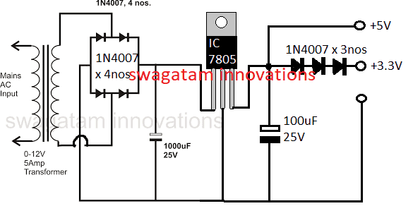
So I am sure that your requirement can be easily fulfilled through the above mentioned procedures.
for powering MCU through the above procedure you can use a 0-9V or a 0-12V trafo with 1amp current, diodes could be 1N4007 x 4nos
The diodes will drop 1.4V when the input is a DC but when it's an AC like from a trafo then the output will be raised by a factor of 1.21.
make sure to use a 2200uF / 25V cap after the bridge for the filtration
I hope the info will enlighten you and answer your queries.
The image above shows how to get 5V and 3.3V constant from a given power supply circuit.
How to Get 9 V Variable Voltage from IC 7805
Normally, the IC 7805 is considered as a fixed 5 V voltage regulator device. However, with a basic workaround, the IC could be turned into a 5 V to 9 V variable regulator circuit, as shown above.
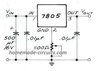
Here, we can see that a 500 ohm preset is added with the central ground pin of the IC, which allows the IC to produce a lifted output value up to 9 V, with a current of 850 mA. The preset could be adjusted o get outputs in the range of 5 V to 9 V.
For getting an increased voltage output from a 7812 IC, you can refer to this post!
Making a Fixed 12V Regulator Circuit
In the above diagram we can see how an ordinary 7805 regulator IC could be used for creating a fixed 5V regulated output.
In case you wanted to achieve a fixed 12V regulated power supply, the same configuration could be applied for getting the required results, as shown below:
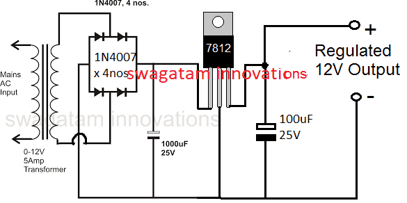
12V, 5V Regulated Power supply
Now suppose you had circuit applications which needed a dual supply in the range of 12V fixed and also 5V fixed regulated supplies.
For such applications the above discussed design could be simply modified by using a 7812 IC and then subsequently a 7805 IC for getting the required 12V and 5V regulated power supply output together, as indicated below:
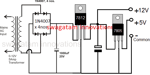
Designing a Simple Dual Power Supply
In many of the circuit applications, especially the ones using op amps, a dual power supply becomes mandatory for enabling the +/- and ground supplies to the circuit.
Designing a simple dual power supply actually involves a just a center tap power supply and a bridge rectifier along with a couple of high value filter capacitors as shown below:
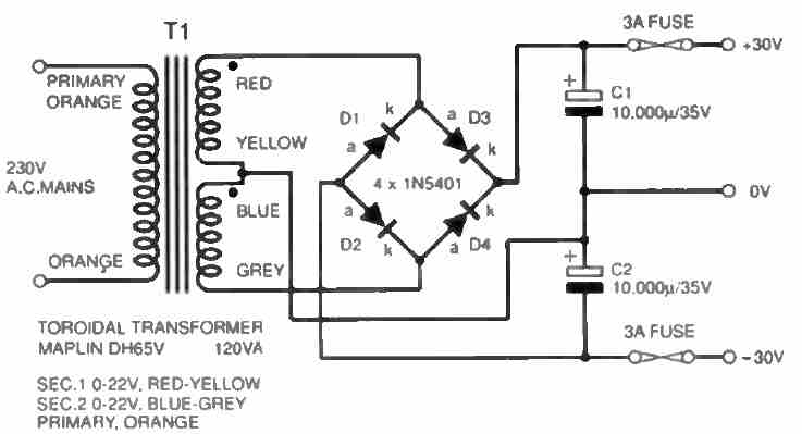
However, for achieving a regulated dual power supply with the desired level of dual voltage at the output is something which normally requires a complex design using costly ICs.
The following design shows how simply and discretely a dual power supply could be configured using a few BJTs, and a few resistors.
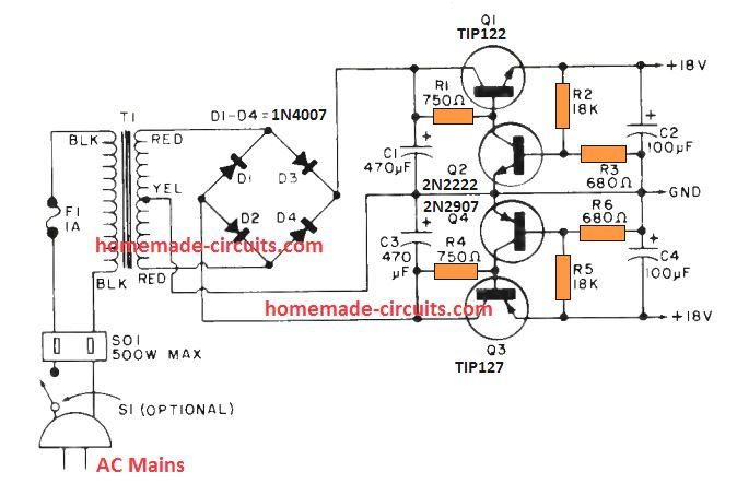
Here Q1 and Q3 are rigged as emitter follower pass transistors, which decide the amount of current that is allowed to pass across the respective +/- outputs. Here, it is around 2 amps
The output voltage across the relevant dual supply rails is determined by the transistors Q2 and Q4 along with their base resistive divider network.
The output voltage levels could be appropriately adjusted and tweaked by adjusting the values of the potential dividers formed by the resistors R2, R3 and R5, R6.
Dual Supply with a Single Opamp
If you an extra opamp left in your circuit that demands a dual supply from a single supply, then perhaps the following simple dual power supply from a single opamp configuration can be tried.
The resistors R1 and R2 work like a high impedance, and consequently economical voltage divider network. The opamp ensures that the artificial ground potential is always identical to the potential bteween the junction of R1 and R2.
The connection between R1 and R2 establishes the relationship between the a couple of output voltages; if R1 and R2 possess the identical value, exactly the same will be ensured for both the output voltages which would be perfectly symmetrical.
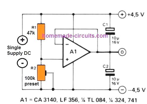
This allows us to get the most desirable feature of the circuit, it is that the R1/R2 partnership doesn't rely on the battery voltage!
An additional benefit of this active potential divider is that (as opposed to a basic resistor divider chain) it adjusts itself nicely to varying load currents moving to and from the earth supply line, especially with regards to unsymmetrical load current situations.
You can probably think of using different variants of opamps for this circuit.
The 3140 and 324 tend to be fantastic choices, despite having a battery voltage as low as 4.5 V.
Keep in mind that the highest voltage that can be tolerated by these ICs is not more than 30 V, and the maximum load current that can be tolerated by the opamp will also depend on the type of the opamp.
Designing an LM317 Power Supply with Fixed Resistors
An extremely straightforward LM317T-based voltage/ current supply, that could be employed for charging Nickel-Cadmium cells or any time a practical power supply is necessary, is demonstrated below.
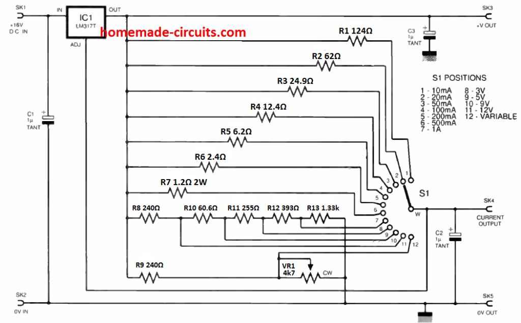
It is an uncomplicated venture for the newbie to construct, and is meant to be utilized with a plug-in mains adaptor providing an unregulated d.c. output. IC1 is actually a adjustable regulator type LM317T.
The rotary switch S1 chooses the setting (constant current or constant voltage) along with the current or voltage value. The regulated voltage can be obtained at SK3 and the current is in SK4.
Observe that a adjustable setting (position 12) is incorporated that enables a variable voltage to be tailored through potentiometer VR1.
The resistor values must be manufactured from the closest obtainable fixed values, positioned in series as necessary.
Resistor R6 is rated at 1W and R7 at 2W although the remaining could be 0.25W. Voltage regulator IC1 317 must he installed to some heatsink the size of which is determined by the input and output voltages and currents necessary.

Getting 5 Amps from a 7812 IC
If you are wondering how to get 5 amp or higher current from a 7812 regulator IC, then the following circuit might be the one you are looking for.
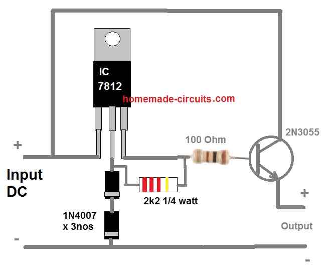
As you can see a power transistor 2N3055 is configured with the 7812 output as an emitter follower for transforming the 1 amp current from the 7812 output into a massive 5 amp current at the emitter of the transistor.
However, there's a drawback of using an emitter follower configuration. It reduces the output voltage by 0.7 V or 1 V due to the base-emitter forward voltage drop specification of the BJT.
To compensate this we raise the 7812 output by around 1 V by adding a couple of series diodes at the GND terminal of the IC.
The 100 ohm resistor at the base of the transistor determines the output current. The 100 ohm value is arbitrarily chosen.
If you find 100 ohms not delivering the intended 5 amps then you can try reducing this value. Just make sure the wattage of the resistor is also appropriately increased so that the resistor does not heat up and burn.
Designing a Basic 741 based Regulator Circuit
Presented below is an exclusive depiction of a dual-stage voltage regulator setup, proficient in delivering approximately 3 Amps at its output.
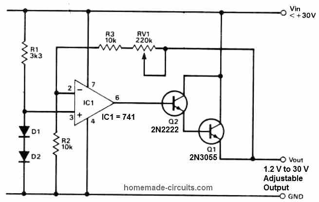
The primary stage incorporates an op-amp IC 741, functioning as a DC voltage amplifier.
An adjustable amplification factor allows a wide array of output voltage options, achieved by employing a reference voltage derived from a stack of diodes as the input signal.
The subsequent stage serves as a current amplifier, efficiently converting the available 10 mA from the op-amp output into a usable 3 A supply current.
Using a Feedback
An intriguing aspect of this configuration is that the current gain stage is integrated into the feedback loop of the system.
Consequently, the regulator's output voltage is determined by the product of the reference voltage and the op-amp gain, where the op-amp gain is calculated from the expression:
A: (Rf + Rin)/Rin.
To obtain this gain value, a potential divider is formed using the total value of the feedback resistors Rf and the input resistor Rin.
This well-engineered setup ensures optimal voltage regulation with high precision, catering to a variety of practical applications.


Questions & Answers
Thanks you!
you mean by using discrete transistors or mosfets??
Hello Sir,
Day's Greet.
I find this site is is very interesting and I like it very much.
Sir,I am using LM2576 to get 5V.
Input to the LM2576 should be minimum 7V.
Max current handling capacity of LM2576 is 3A
My transformer is 9V,1A.
Load is 0.70A.
What should be the value of capacitor.
I got the value of load from DC power supply by providing 9V at the input of Bridge rectifier.
Please, suggest the solution and its formula.
Please reply me this here as well as on my email-id n_nogaja@yahoo.co.in
You can refer to the following post, it explains the entire procedure of calculating filter capacitors in power supplies.
http://www.tpub.com/neets/book7/27e.htm
thank you for everything sir.
but I developed a 5v power supply, it works well but my worry is that the output current is to small so, how can I increase it thank you.
The output current will depend on the transformer rating….if you have used a 7805 IC the transformer could be rated at 1 ampere.
Thanks for the article.
I need to step-up 8V(p-p) 1MHz AC signal,which type of transformer should I use?
you will need a ferrite ring type of transformer for this.
Sir please can u give more details on this? and is it easily available? I require it on urgent basis.
you can try a joule thief circuit kind of configuration for your application.
you will find plenty of such designs on the web.
Thank you sir for the reply.
Sir,on the receiver side I'm getting enough voltage but very low current.I need to amplify current but at the same time voltage should not drop more than 1V.How can I do that?
which circuit you have used, pls provide me the link.
Hello sir,
what do you think about adding non-polar caps in parallel to each diode in the bridge network configuration? do these guys provide better stability??
Do you suggest me connecting a resistor at the output after the electrolytic cap?
does connecting resistor reduce hum on the DC output.
Please help in such thoughts.
Hello Sherwin, such enhancements are not crucial and may be ignored, because the circuits which would be operated using these supplies would be already sophisticated enough to tackle such small inefficiencies from the power supply.
can i get 1.8v and 2.2amos by using this circuit??
the last circuit using LM338 IC will give you this.
RC time constant has no relevance to a power supply, if you are referring to the filter capacitor formula you can easily find it online, just type: "power supply filter capacitor formula" you'll find many related sources
Hello Sir ,
you are running an excellent block….
can u tell me how can i design a 15v 1A power supply ???
Thanks Sayli,
If you want to build an SMPS type of power supply then you can try the following design:
https://www.homemade-circuits.com/2012/03/how-to-make-simple-12-v-1-amp-switch.html
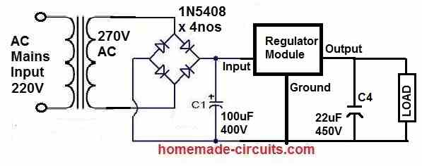
for a transformer power supply you can simply use a 0-12V transformer and join a bridge rectifier with a filter capacitor, as shown in the third diagram above for getting a 15V output
Sir can you tell me how do we decide the value of capacitor used as a filter ??
there is a formula for it, however practically it's never required because most electronic circuits will work nicely even if there's a slight ripple….but as a rule of thumb it's recommended to use a value that may be as high as possible from the user, because the degree of filtration is directly proportional to the value of the cap (uF)
Dear sir i need a power supply constant 0.9V and at least 20mA of current can you give me a circuit because i am newer to this things please help me
Dear Suresh, why do you need a constant 0.9V, and for what application, please let me know so that I can configure a proper design for you.
Hello sir,
Thank you for providing this blog. Its very useful.
it's my pleasure Vicky.
Dear sir,
I have made one development board of Pic18f4520 Microcontroller. And now i need to provide it exact 5 volt dc power supply. Please help me in designing power supply. What should i do?
Dear Vicky, you can use a 7805 IC circuit for getting a regulated 5V. check the datasheet of the IC you'll get the required diagram there.
Hello sir,
I would like to ask that what is the use of bridge rectifier in power supply
Hello Ashok, it's to channelize both positive and the negative half cycles of the AC into only positive cycles….thus the negative and the positive cycles both are converted to positive cycles.
how to calculate capacitor rating for 5 volt power supply??
you can try the details presented in this article:
https://www.homemade-circuits.com/2015/11/calculating-filter-capacitor-for.html
Namaste Swagatam,
https://www.homemade-circuits.com/2012/03/how-to-design-power-supply-simplest-to.html
In the first diagram in above article, you show a HALF WAVE rectifier, yet the diagram says FULL WAVE.
You need to fix that if you want to teach and not confuse!
Have a nice day!
Jeff
Good day, sir.
It was mentioned that, in PS circuit designs without ICs, the outputs have “ordinary regulation” and “fail to provide ideal DC output”. Can you please elaborate? Also, does this mean that, when viewed using an oscilloscope, the output voltage is not linear (specifically, horizontal)?
I have been wondering about this for hours and my teacher won't answer me. It would be great to know about some enlightenment. 🙂
Good day Chritian,
regulation refers to voltage and current being constant, but the level of pureness of the DC is governed by the filter capacitor not by the IC….therefore the cleaning the DC is done by the filter cap while the ICs make sure that the voltage and the current remain steady all throughout regardless of the input fluctuations.
the straightness of the DC horizontal line is essentially controlled by the filter capacitor
Thank you so much, sir! Have a good day.
Hello swagatam,i'm using 7805 regulator in my power supply. Which diodes should i use, and how to decide the specifications of capacitor that need to be used for getting 5V output.
Hello Sumit, you can use 1N4007 diodes for the bridge rectifier, and filter capacitor can be anything above 1000uF/25V, it's not critical.
Sir you use voltage regulator circuit with ic LM338 can i replace it with just the ic of voltage regulator e.g. 78XX05 or anyother else?
Zunair, No, it's not possible in the LM338 circuit, you can use it with a different configuration if you intend to achieve a fixed 5V from it.
I am a teacher and want to build a classroom noise monitor with my students. So we need a circuit diagram of classroom noise monitor, if you can help us.
you can try the following circuit:
/blog/2016/02/sound-decibel-meter-circuit.html
Good day thanks so much for your kindness in sending us the circuit. But please I have some questions first can we design the power supply of the sound decibel meter circuit using a centre tapped transformer, secondly we want to use buzzers and incandescent lamps for the design instead using only LEDs. Reason is that we want to draw students attention with buzzer and lamp when the noise level in the classroom is high. Regards
you can use a center tap transformer for powering the circuit, as shown in the second circuit above.
and you can easily reparable the LEDs with 12V piezo buzzers for the relevant indications.
Sorry sir pls what do you mean by 'reparable'
sorry, i meant to say "replace"
What pot value did you use? Increase its value and you will be able to acquire the whole range. try a 22K pot that will be enough
Sir, I want to build a sterio amplifier using IC LM3886 two no. Purchase power supply ready board low ESR using 4700×8 cap in dual rail.( I.e. + and – ). I am getting a 50hz noise. Transformer using 18-0-18 3A. I deside to use a load resistance, but the value how to calculate? Will u suggest to replace the transformer? (As the transformer become very hot within short period.) Circuit I have purchased from eightaudio.com. they suggest to use 22-0-22 4A transformer. Please help me.
Jyotirmoy, you will need to install the entire amplifier board and the power supply transformer inside a good metal cabinet, once this is done the 50Hz ripple will be significantly reduced.
Make sure to connect your amplifier negative line with the metal box, and also make sure the transformer is tightly clamped with the box using nuts and bolts.
If your transformer is becoming HOT then it's not rated correctly or is of bad quality, replace it with a new one as per the recommended specifications of the amplifier and use a good quality transformer from a standard manufacturer.
Sir,
Hoping you maybe able to assist with an issue with a power supply on a pre-amp.
The pre-amp has been upgraded several times and along with it the power supply, originally it had 4 small capacitors each 1000 uf then they were replaced with 1,000uf x 100v and the toroid was replaced with a 600va x 71/0/71…every thing worked well for 8 years until last weekend until I decided to upgrade the capacitors to 6,800uf each (two each feed), they slotted in just perfect and when switched on was just excellent, every thing was just spot on i.e. 71/0/71 ac in and 90/0/90dc to the main board on the board sits 4 little Nu-Vista valves hence the 90volt output…….I then connected the power supply to the main board and switched on and BANG..the tracks from the A/C input on both had been taken out thro the 3 filter caps (104j x 250v) and only up to the rectifier (W04M 1.5amp) everything else was fine…put the P/S back as it was and the pre-amp works just fine…….Question, what went wrong?…too much capacitance or as I feel the rectifier needs beefing up as the other was small and only 1.5amp…oh and between the main caps are two resistors 330 ohm 2 watts metal film +/- 1%
Your input with this would be greatly appreciated
Mick
Hi Mick, It can be difficult to judge precisely without seeing the damaged area practically, yes increasing the capacitor value could have caused this due to an increase in the current level, and if the tracks got burnt then certainly something across these tracks could not handle the current generated from the 6800uF cap.
the 330 ohms are no match for 91V, even though these are rated at 2 watt still these would begin smoking at 91V….but tracks getting burnt is strange unless something shorted them across the supply rails…you will need to find the weak link between these tracks which might have triggered the issue.
Hi, again…I could send you images, the tracks destroyed go from AC in to the rectifier and no further….getting a bigger rectifier tomorrow so we shall see, nothing has changed over the past 8 years apart from these new caps, the only thing that was between the rectifier and AC in were three 104J x 250 volt caps for I assume smoothing…..will get back to you in a few days and let you know which part of my house wall is still standing….many thanks for your time
Mick