• Skip to main content
  • Skip to primary sidebar

Homemade Circuit Projects

Need circuit help? Post them in the comments! I've answered over 50,000!

Blog | Categories | About | Hire Me | Contact | Calculators-online
You are here: Home / Temperature Controllers / How to Make an Incubator Timer Optimizer Circuit

How to Make an Incubator Timer Optimizer Circuit

Last Updated on January 2, 2024 by Swagatam 190 Comments

A timer circuit design which could be used for turning the position of the eggs in an incubator between predetermined intervals of time was requested to me by one of the keen readers of this blog, Mr. Eugene.

Table of Contents
  • Circuit Specifications
  • Designing an Incubator Egg Timer Circuit
    • Circuit simulation:
    • Using Rotary Switch for Adjusting the Time intervals

The requested circuit has been exclusively designed by me and published here,

Circuit Specifications

Let's hear the whole episode:

I'm raising chickens for derby and I have hen that is laying eggs. For the hen to continue laying eggs, I need to incubate the eggs. I have researched incubator designs and parts and I have already assembled a simple one. I have a digital 220V ac thermostat and in order to protect it, it will only have to drive a 220V relay. This one already worked well.

Now I have an additional info that the eggs have to be rotated or moved upside down 3 times a day in order for the eggs to hatch well. I am planning to make a rows of eggs holder chained or built together driven by a motor such as electric fan swing motor. Its strong and moves very slowly and I think its quite enough. This 220v ac motor will be driven by a 6v dc relay. Now I need a relay driver circuit and a timer circuit that wil trigger the relay driver more or less every 8 hours for approximately 3 seconds only.

I may not have enough words to reach 300 but I think my intention is clear enough. But if the blog requires 300 words, I will try to extend my explanation.

Thank yo very much and I hope you can help me.

Eugene"

Designing an Incubator Egg Timer Circuit

The circuit of the proposed incubator egg timer and optimizer is given below:P1 should be adjusted for the long 8 hour duration and P2 for the short 3 seconds duration.

Circuit simulation:

Looking at the circuit diagram we can see that it consists of two identical IC 4060 stages which are coupled across each other for implementing the proposed actions.

The upper timer stage is intended for producing long time intervals and therefore its output is taken from pin #3, while the lower IC generates smaller time intervals and so its pin #15 is chosen as the output.

When power is switched ON the following things happen with the circuit:

The 0.1uF capacitor resets the upper IC so that it can start counting, during this period its pin #3 is at logic low which keeps the relay driver stage switched OFF, also the lower BC547 is kept disabled, which keeps pin #12 of the lower IC at high logic which in turn renders the lower IC inactive.

After the predetermined period is lapsed, pin #3 of the upper IC goes high, this switches ON the relay driver stage and also the lower IC pin #12 gets reset, this toggles the lower IC into counting mode.

After the predetermined period, pin #15 of the lower IC becomes high, which sends a logic high to the reset pin #12 of the upper IC, resetting it back to its original position......the cycle repeats, and goes on repeating as long as power is available.

The lower section can be upgraded for generating higher time intervals at par with the upper section by replacing pin15 with pin3 as already done in the diagram below.

The relay contacts are wired up to the motor for shuffling the egg orientation.
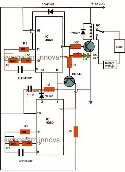
programmable incubator timer circuit

Using Rotary Switch for Adjusting the Time intervals

If you find adjusting the pot difficult and time consuming, you could easily replace them (P1, P2) with rotary switches as shown below. The involved could be also easily calculated with some quick and experimentation:
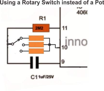
 

timer circuit with rotary switch

You'll also like:

  • UntitledSketch bbTemperature Controlled DC Fan Circuits
  • HowtoMakeaSimplePeltierRefrigeratorSimple Peltier Refrigerator Circuit
  • atomizerAtomizer Circuit for E Cigarettes
  • simple temperature controller circuitTemperature Controller Circuit for Reptile Racks

Filed Under: Temperature Controllers Tagged With: Incubator, Optimizer, Timer

About Swagatam

I am an electronics engineer and doing practical hands-on work from more than 15 years now. Building real circuits, testing them and also making PCB layouts by myself. I really love doing all these things like inventing something new, designing electronics and also helping other people like hobby guys who want to make their own cool circuits at home.

And that is the main reason why I started this website homemade-circuits.com, to share different types of circuit ideas..

If you are having any kind of doubt or question related to circuits then just write down your question in the comment box below, I am like always checking, so I guarantee I will reply you for sure!


Previous Post: « Designing Simple Power Supply Circuits
Next Post: Simple Car Shock Alarm Circuit »

Reader Interactions

Questions & Answers

Total Posts: 190
Newest Oldest
Joseph Nzuza
September 18, 2022 • 4 years ago #133344

Hello Sir;
In line with hatched chicks, I would like to build make circular brooder house with an automatic temperature controller. Not using a microprocessor chip is it possible to design a temperature controller which will switch off when the temperature reaches a set high point and turn ON heaters when the temperature is below the set lower values?
Thanks in advance.

Reply
SwagatamAdmin
September 18, 2022 • 4 years ago #133348

Hello Joseph,
You can try the second last circuit from the following article, which uses the IC LM35:

https://www.homemade-circuits.com/how-to-build-simple-electronic/

Reply
Yabagi
November 15, 2020 • 6 years ago #84437

Hello Mr swag,
This is a good design , but my question is how can I interface a digital display to the circuit to read the predetermined time directly?

Reply
SwagatamAdmin
November 15, 2020 • 6 years ago #84446

Thanks Yabagi, you can use the following circuit, and configure with the relay output of the timer

https://www.homemade-circuits.com/5-digit-frequency-counter-circuit/

the frequency input can be from a 1 second oscillator using IC 555….precision may not be critical

Reply
rudrud
September 11, 2018 • 8 years ago #63181

hi sir If possible I’ll try the circuits you shared.. Thanks

Reply
SwagatamAdmin
September 11, 2018 • 8 years ago #63197

Thanks Rudrud, please do it and if possible provide a small video clips to my email.

Reply
Ken
July 31, 2018 • 8 years ago #62077

Sir what caps i will ceramic or mylar caps?,.help me sir thanks

Reply
Ken
December 17, 2018 • 8 years ago #64537

Sir the push button is for reseting purpose?,..because some time when i turn off the circuit and turn on again,the lower ic continues to count,..the upper ic not reseting properly,..

Reply
SwagatamAdmin
December 17, 2018 • 8 years ago #64547

Ken, which push button are you referring to?

Reply
Ken
August 29, 2018 • 8 years ago #62737

Sir i made the circuit and its working,.thanks for the design and the assistance sir,….

Reply
SwagatamAdmin
August 30, 2018 • 8 years ago #62741

I am glad about it Ken, keep up the good work!

Reply
Ken
August 31, 2018 • 8 years ago #62758

Sir when i connect led in pin#14 the blink is to slow sir,.what should i do sir to make the blink fast,..and does the capacitor in pin#9 affects the time interval,..how to compute ur desired time sir,.thanks

Reply
SwagatamAdmin
August 31, 2018 • 8 years ago #62761

Try pin#7. Yes capacitor at pin#9 and resistor at pin#10 together are responsible for time delays or the frequency:

https://www.homemade-circuits.com/how-to-understand-ic-4060-pin-outs/

Reply
Ken
August 29, 2018 • 8 years ago #62730

Sir if i remove the resistor P1 and P2,..what should b the initial time interval and the limit rotation of the motor?thanks sir ,..the circuit is working sir,.i just want to know the intial time so i can make a switch interval sir,.thanks sir swag

Reply
SwagatamAdmin
August 29, 2018 • 8 years ago #62732

Please see the video in the following article, it will allow you to judge the approximate delay at pin#3. In the video I used 10K at pin#10 and 0.1uF at pin#9

https://www.homemade-circuits.com/how-to-make-simple-programmable-timer/

Reply
Ken
August 29, 2018 • 8 years ago #62729

Sir if i remove the resistor P1 and P2 what should be the initial time interval and time limit of the rotation motor sir?,.thanks

Reply
Ken
August 29, 2018 • 8 years ago #62728

Sir can i use 12.6v as a supply voltage,.?,…and if i put the supply the red LED starts to light right?,..my circuit is not working pls help,thanks

Reply
SwagatamAdmin
August 29, 2018 • 8 years ago #62731

Ken, yes the red will light up on switch ON, please refer to the articles for all the details:
https://www.homemade-circuits.com/how-to-make-simple-programmable-timer/

you can connect a LED/1K across pin#14 and ground to check the timer response, this LED will start blinking while the specific IC is counting

Reply
Ken
August 23, 2018 • 8 years ago #62634

Sir i have ac 220v motor it indicates CCW/CW what its mean sir?..it can turn clockwise and counter clockwise?help sir,.thanks

Reply
SwagatamAdmin
August 24, 2018 • 8 years ago #62639

Hi Ken, there’s a lot of information available online, if you search “CCW/CW motor” you will be able to find the answers quickly….

Reply
SwagatamAdmin
August 1, 2018 • 8 years ago #62082

you can use any type of capacitor as long as it is non-polar.

Reply
Ken
August 1, 2018 • 8 years ago #62086

Sir all value of capacitor is 1uf/25v?

Reply
SwagatamAdmin
August 1, 2018 • 8 years ago #62087

Ken, it can be 1uF or you can change them as per your own choice, higher values will give higher time delays proportionately….

Reply
Ken
August 3, 2018 • 8 years ago #62120

Sir what is the value of the capacitor in IC 2 between pin16 and 1M,..is it 1uf or 0.1uf…because in the 1st diagram it is 0.1uf and the other diagram is 1uf,…..and i can use 3v dc motor as trial motor?thanks sir

Reply
SwagatamAdmin
August 3, 2018 • 8 years ago #62121

Ken, I have already answered to your question, use 1uF it will give a better resetting action. for a 3V motor you will need a 3V supply across the relay contact wiring.

for the circuit make sure it is above 4.5V

Reply
Ken
August 2, 2018 • 8 years ago #62108

Sir the capacitor in ic 2 connecting the no.16 pins to the ground,.what is the value sir?,.its 1uf or 0.1uf?,…thanks sir

Reply
SwagatamAdmin
August 3, 2018 • 8 years ago #62114

you can use 1uF there for better resetting action during power switch ON….you can use polarized capacitor, positive lead will connect with pin#16 line

Reply
Anjali kashyap
July 7, 2018 • 8 years ago #61520

Thank you sir for your wonderful work. Can I get PCB layout of it ?? Sir please both side or back side only ,
Only you can sir because you are the best I am waiting please sir

Reply
SwagatamAdmin
July 7, 2018 • 8 years ago #61521

Glad you liked my work Anjali, you can find the PCB design in the following post:

https://www.homemade-circuits.com/how-to-make-simple-programmable-timer/

Reply
Fuzail kareem
June 18, 2018 • 8 years ago #61052

Sir which type of rotary switch I use pls rply

Reply
SwagatamAdmin
June 18, 2018 • 8 years ago #61061

You can use single pole multiple contact rotary switch, the number of contacts will depend on the maximum number of time intervals you may prefer to use

Reply
Fuzail kareem
June 19, 2018 • 8 years ago #61072

Yes, thank you sir 🙂
One more questions sorry 🙂
I think it is good to use p1 rotary because it need time interval and p2 need duration of time so p2 should be a 1pot ?
Sir I just think but you are the inventor and you are the master! What is your idea ??

Reply
SwagatamAdmin
June 19, 2018 • 8 years ago #61086

You are welcome Fuzail, rotary switch can be used for both the timers, because the selected resistors will allow you to get the precise time intervals as required by you. First try a randomly selected resistor and check the ON + OF time interval at pin#3, then you can add more selectable resistors calculated proportionately for getting other time delay options

Reply
Fuzail kareem
June 11, 2018 • 8 years ago #60889

Hii sir,
My name is Fuzail Kareem first txn for your good and helpful work I really like you website and your work
Sir my question is how can I change both on and off time as according to my need sir it why because egg need to turn daily (circut on time ) 3-5-7 time and also It must be necessary to every egg it turn whole I mean front to back and it take time more than 3 second and depend quantity of egg
Pls reply sir

Reply
SwagatamAdmin
June 11, 2018 • 8 years ago #60897

Hi Fuzail, you can replace P1 and P2 with rotary switches and set the timing as per your preferences, please check out the last updated diagram

Reply
Yao
October 15, 2021 • 5 years ago #101512

Hello i buld the circuit but i have a problem my led is flashing . please help me. Thanks

Reply
Fuzail kareem
June 11, 2018 • 8 years ago #60900

Txn for your valuable response

Reply
Ken
April 10, 2018 • 8 years ago #59699

Sir Swag , P1 and P2 (100k resistor) is a variable resistor?pls help,.thanks

Reply
SwagatamAdmin
April 11, 2018 • 8 years ago #59708

yes those can be 1M pots or presets

Reply
Ken
April 9, 2018 • 8 years ago #59672

Hi! Sir what Load and Supply voltage i wll use in the circuit?,itry to make the circuit and i dont know what to use,pls help me sir,im newbie,thanks

Reply
SwagatamAdmin
April 9, 2018 • 8 years ago #59675

Hi Ken, load will be your motor for shuffling the eggs, and the supply input will be the voltage as per the motor specs.

Reply
Ken
April 10, 2018 • 8 years ago #59698

Sir,whats the value of the relay?thanks

Reply
SwagatamAdmin
April 11, 2018 • 8 years ago #59707

relay can be any standard 12V relay

Reply
Ken
April 10, 2018 • 8 years ago #59695

Thanks si swag,…sir what direction of the rotation of the motor?is it clockwise or counter clockwise?,..or both clockwise and counter clockwise?,…

Reply
SwagatamAdmin
April 11, 2018 • 8 years ago #59721

Ken, you can try the following concept

https://www.homemade-circuits.com/programmable-bidirectional-motor-timer/

Reply
Ken
April 10, 2018 • 8 years ago #59697

Sir swag,.how can i make the 1st turn of motor is clockwise and the 2nd turn is counterclockwise,…alternate sir,..pls help,thanks

Reply
SwagatamAdmin
April 11, 2018 • 8 years ago #59706

Ken,

You can try the following concept for getting a bidirectional motor operation

https://www.homemade-circuits.com/programmable-bidirectional-motor-timer/

Reply
Fuzail kareem
January 6, 2018 • 9 years ago #57409

Can you pls make a egg turner and also DC mother speed control with desirable direction and with two direcation

Reply
SwagatamAdmin
January 7, 2018 • 9 years ago #57419

If possible i will try to update the article with these info soon

Reply
Ken
April 9, 2018 • 8 years ago #59673

Can i use 220V AC supply as Supply voltage?,..pls help,.thanks

Reply
SwagatamAdmin
April 9, 2018 • 8 years ago #59674

yes you can if the load is also rated to work with 220V

Reply
Asif
November 5, 2017 • 9 years ago #55570

Hi.
Anybody can supply me this timer. O anybody compleeted this timer. Call me on 84949 15158
Thanx.

Reply
Asif
November 5, 2017 • 9 years ago #55581

Can i have ur cell number. I need 6 sets or atleast 1 for my hatcher.

Reply
SwagatamAdmin
November 5, 2017 • 9 years ago #55576

I have built this timer many times with 100% success. It is one of my best designs.

Reply
Imran yousaf
October 3, 2017 • 9 years ago #54465

Sir I need help on how to make Display on this circuit for temperature with LCD display , is it possible with this circuit? Any link or help will be highly appreciated …

Reply
SwagatamAdmin
October 4, 2017 • 9 years ago #54480

Imran, you can use an LM3915 IC for making a bar graph type temperature indicator circuit, but it will need to incorrectly integrated with the tempwerature sensor.

Reply
Balu 2011
January 30, 2017 • 10 years ago #48509

bro you told to me permanent magnet brushed type to this circuit is that motor dc or ac motor and which motor works with this circuit dc motor or ac motor

Reply
SwagatamAdmin
January 31, 2017 • 10 years ago #48517

it's a DC motor,

the above circuit uses a relay, which means you can use any motor, does not matter whether it is a DC or AC, you just need to connect the relay contacts accordingly with the relevant supply input and the motor

Reply
Michael Vino
January 30, 2017 • 10 years ago #48507

DEAR SIR, Can u please adjust the circuit for every 2 hours interval switch on 3 seconds only for my homemade egg turner. I am new here. Please let me know the resisters for UPPER IC (2 hrs interval) also capacity of potential meter to be used. Also let me know which resisters can be used for LOWER IC (3 seconds) and also explain about the capacity of relay. I am going to use 12v 3.7 RPM motor

Reply
Michael Vino
February 1, 2017 • 10 years ago #48532

Thank you very much sir. If any of friends have already built diagram like 2 hrs off and 15 seconds on, please send to my email id [email protected]. Thank u very much

Reply
SwagatamAdmin
January 31, 2017 • 10 years ago #48514

Dear Michael, It won't be possible for me, because it will need to be done with practical experimentation.

you can do it in the following manner:

in the above given set up you can keep the P1 short circuit so that only R2 becomes the timing component.

Switch ON power and using a stop watch check after how many seconds the green LED lights. Note this down and from this data you can find out the other required timing cycles using the following simple cross multiplication;

P1+R2/R2 = x/Recorded Time, where x is the desired time interval.

for example if you got 10 seconds from the above experiment and the desired interval is 2 hours (720 seconds), then the formula could be solved as:

(P1 + 100)/100 = 720/10
P1 + 100 = 7200
P1 = 7200 – 100 = 6200K

Remember the above calculation is just an example, and the figures are arbitrarily selected.

Reply
Ken
July 19, 2018 • 8 years ago #61781

Why P1= 7200-100=6200k
how it happen sir,..thanks

Reply
Balu 2011
January 28, 2017 • 10 years ago #48452

bro can you please send the list of all components for this circuit i mean how many resisters and how many capasiter ect please bro

Reply
Balu 2011
January 26, 2017 • 10 years ago #48385

bro small dout ani limit switches in this circuit sorry for asking ian completely accounts student thats why i am asking doutes thanks in advance

Reply
SwagatamAdmin
January 27, 2017 • 10 years ago #48410

Balu, this is a timer circuit, no limits are included here, you may have to adjust the speed of the motor to match with the selected timing interval of the circuit

Reply
Balu 2011
January 26, 2017 • 10 years ago #48384

ok which motor is best for this circuit bro

Reply
SwagatamAdmin
January 27, 2017 • 10 years ago #48421

a permanent magnet brushed type will do…

Reply
SwagatamAdmin
January 27, 2017 • 10 years ago #48420

it will depend on the load, that is the number of eggs that may be required to be moved by the motor.

Reply
Balu 2011
January 23, 2017 • 10 years ago #48283

hai bro, can u send the pic circuit board i cant understand your picture so please send some pics of buided circuit board and limit switch s pics please thanks in advance

Reply
SwagatamAdmin
January 24, 2017 • 10 years ago #48291

please click on the diagram to enlarge it, you will be able to see all the components and their numbers clearly.

Reply
DINESH KUMAR
August 7, 2016 • 10 years ago #43353

Bro, can I use 1uf/400v polyester type capacitor

Reply
SwagatamAdmin
August 8, 2016 • 10 years ago #43373

yes you can use it

Reply
DINESH KUMAR
August 6, 2016 • 10 years ago #43312

Hello Sir 1uf/63 capacitor is not available in my location.
What to do?

Reply
SwagatamAdmin
August 6, 2016 • 10 years ago #43331

Dinesh, you can use many 0.47uF/50V capacitors in parallel….

Reply
fuzail kareem
June 24, 2018 • 8 years ago #61151

sir i am again
cant get 1uf non polar
i just got 474j 450 volt
is it work?? am i use 2 in parallel

Reply
SwagatamAdmin
June 24, 2018 • 8 years ago #61152

Hi Fuzail, yes definitely you can use two of them in parallel, it will work

Reply
DINESH KUMAR
August 3, 2016 • 10 years ago #43225

Hello Sir can I use bc548 and replace c1 47uf/63v ,p1 220 kilo ohm ,R2 470 kilo ohm.please reply me

Reply
SwagatamAdmin
August 4, 2016 • 10 years ago #43257

hello Dinesh,

will do, however P1 and the 1uF parts decide the time length…220K , and 470K are fine, but try using more numbers of 1uF/63 in parallel to get higher delay ranges. it must be non-polar

Reply
Kakinyi Mutua
June 30, 2016 • 10 years ago #42228

hello am new in electronics .can someone please provide me with a pcb for this timer

Reply
fetah71
June 14, 2016 • 10 years ago #41797

Hello my brother I buy a relay timer FRM01 12v I not how conect my 220volt 4watts engine can show my a diagram Please, I need to turn the egg

Reply
SwagatamAdmin
June 15, 2016 • 10 years ago #41806

with a multimeter in the diode range check which outputs of the relay close or open while the timer is counting or finished counting….with this info you can connect the motor with these contacts accordingly

Reply
The Engineeer
February 14, 2016 • 11 years ago #38755

I have a +5V output in my incubator, the timer circuit should work OK with that, right?
Of course, I need a relay with a 5V coil instead but other than that I don't see any problems.

Reply
SwagatamAdmin
February 15, 2016 • 11 years ago #38774

yes that's correct, either you can use a 5V relay or you can opt for a triac control for the load

Reply
Harvest Palm
November 23, 2015 • 11 years ago #36168

I have built it again, i think the upper ic work well, i check with led pin 15 and it blink and i have changed pot with 500k and it work good. But the lower ic become touch sensor. When i touch the output ( NC/NO) relays wired, the led lower ic blinks but when i do not touch it, blinks stop and next on like that, what happen on my circuit, please help sir, i am new on elektronics

Reply
SwagatamAdmin
November 24, 2015 • 11 years ago #36177

the lower IC will not function until the upper IC has finished counting, …..in other words when the lower BC547 is triggered only then the lower IC will start functioning……in other words when pin12 of the IC is held at the ground potential only then it will start counting and functioning.

Reply
Harvest Palm
November 20, 2015 • 11 years ago #36048

this is the image sir, please check, maybe something I missed
https://drive.google.com/file/d/0BwFU-bL_-g3deDRxU1QtVGdTYzdvMU1xWEtaZ1VCcVplOGpr/view?usp=sharing

Reply
Michael Vino
January 22, 2017 • 10 years ago #48254

DEAR SIR, PLEASE SEND SIMPLE DIAGRAM FOR EGG TURNER TIMER CIRCUIT AND THERMOSTAT CIRCUIT FOR CHICK INCUBATOR. I HOPE U WILL DO THE BEST. PLEASE SEND TO ME EMAIL [email protected]

Reply
SwagatamAdmin
November 20, 2015 • 11 years ago #36065

OK, I can see it now, but to trace it correctly from my side would be quite time consuming…so you might have to confirm it yourself with the given diagram…the diagram is cent percent correct.

Reply
Harvest Palm
November 18, 2015 • 11 years ago #35990

thanks sir, I almost success to built it, when I connected led across pin 7 via 1 k resistor the led blink fast, and also pin 15 also blink and slowly but the P1 cannot change blink speed, the other hand, the lower IC do not blink. whats going on, I have drown pcb lay out. please check sir, maybe something wrong on the connection that I dont know.
https://drive.google.com/open?id=0BwFU-bL_-g3deDRxU1QtVGdTYzdvMU1xWEtaZ1VCcVplOGpr

Reply
SwagatamAdmin
November 19, 2015 • 11 years ago #36009

your image is not opening because it's not "shared"

Reply
SwagatamAdmin
November 19, 2015 • 11 years ago #36008

Harvest,

the lower IC will function only when the upper IC time period has elapsed and the lower IC is triggered.

your pot may be faulty or not properly selected make sure its value is 1M and its pins are correctly connected

Reply
Harvest
November 17, 2015 • 11 years ago #35950

hi sir i use adaptor 12 v 1 a. Nothing diffrence with the firs time, led on and dreary, when i connected led across pin 16 and ground via 1 k resistor, this led on and brightly. When i connected led across pin 15 and ground via 1k resistor nothing happened led still off, would you like to help me this issue,,

Reply
SwagatamAdmin
November 18, 2015 • 11 years ago #35978

Harvest, initially the red LED should be ON brightly, and when the time elapses for the upper IC, red LED should shut off and green LED should illuminate….if connected at pin16 or pin 15 the LED should flash

I think something's not right with your connections or the circuit.

Reply
Harvest Palm
November 16, 2015 • 11 years ago #35937

I use 12 volt dc transformerless power supply, when I first operated it, the red led is on but its dreary i think because its current input low, after that i have been waiting long and nothing happened, the red led still on. Whats going on sir? I use 2M for R1

Reply
SwagatamAdmin
November 17, 2015 • 11 years ago #35945

check with a 12V AC/DC adapter for confirming the circuit operations, and anyway a transformeless power supply might not work, it could produce wrong results and might not be capable of the driving the relay….
2M is fine for R1

C1 must be non-polar

Reply
Harvest Palm
November 16, 2015 • 11 years ago #35898

Hi sir can i use 12 V transformerless adaptor to be the power supply to this circuit? I have made the adaptor, but im not sure about amp issue, please help,,
Regards

Reply
SwagatamAdmin
November 16, 2015 • 11 years ago #35925

Hi Harvest, the current is not important, but make sure the voltage is strictly within 15V, then it can be safe to use.

Reply
riya
January 23, 2015 • 12 years ago #28357

Hallo sir,
Im having a prob, at first i made the circuit without led and keep it for aomedays and it was working very good, after somedays i try to add the led but when i power it on relay activates with red led, but when i disconnect the red led the device works good again, what could be tje problem sir? Thanka

Reply
SwagatamAdmin
January 24, 2015 • 12 years ago #28366

hello riya,

try a higher value series resistor with the red LED, use a 10K or 15K resistor and check the response.

Reply
View Older Comments

Need Help? Please Leave a Comment! We value your input—Kindly keep it relevant to the above topic! Cancel reply

Your email address will not be published. Required fields are marked *

Primary Sidebar


Categories

  • Arduino Projects (95)
  • Audio and Amplifier Projects (134)
  • Automation Projects (18)
  • Automobile Electronics (104)
  • Battery Charger Circuits (90)
  • Datasheets and Components (109)
  • Electronics Theory (150)
  • Energy from Magnets and Earth (41)
  • Games and Sports Projects (11)
  • Grid and 3-Phase (20)
  • Health related Projects (27)
  • Home Electrical Circuits (13)
  • Indicator Circuits (16)
  • Inverter Circuits (98)
  • Lamps and Lights (161)
  • Meters and Testers (72)
  • Mini Projects (28)
  • Motor Controller (68)
  • Oscillator Circuits (30)
  • Pets and Pests (15)
  • Power Supply Circuits (91)
  • Remote Control Circuits (50)
  • Security and Alarm (65)
  • Sensors and Detectors (107)
  • SMPS and Converters (46)
  • Solar Controller Circuits (62)
  • Temperature Controllers (44)
  • Timer and Delay Relay (50)
  • Voltage Control and Protection (44)
  • Water Controller (37)
  • Wireless Circuits (31)


Circuit Simulator

circuit simulator image


Subscribe to get New Circuits in your Email


Other Links

  • Privacy Policy
  • Cookie Policy
  • Disclaimer
  • Copyright
  • Videos
  • Sitemap

People also Search

555 Circuits | 741 Circuits | LM324 Circuits | LM338 Circuits | 4017 Circuits | Ultrasonic Projects | SMPS Projects | Christmas Projects | MOSFETs | Radio Circuits | Laser Circuits | PIR Projects |


Recent Comments

  • Swagatam on Simple Low Dropout Regulator Circuits Explained
  • Swagatam on How to Calculate Transformerless Power Supply Circuits
  • Swagatam on 5 Simple Water Level Controller Circuits
  • Swagatam on Control a Relay ON OFF Using SIM Card, Mobile Phone, and Arduino
  • Louis83 on Control a Relay ON OFF Using SIM Card, Mobile Phone, and Arduino

Social Profiles

  • Twitter
  • YouTube
  • Instagram
  • Pinterest
  • My Facebook-Page
  • Stack Exchange
  • Linkedin

Calculators

  • ZVS Induction Heater + Tank Calculator Tool
  • Zener Diode Calculator
  • Wire Current and Thickness Calculator (Ampacity Calculator)
  • Voltage Divider Calculator
  • Transistor Base Resistor Calculator
  • Transistor Astable Multivibrator Calculator
  • TL431 Calculator
  • Solar Panel, Inverter, Battery Calculator
  • Ferrite Core Air Gap Calculator Tool
  • Parallel MOSFET Calculator Tool: How to Connect MOSFETs in Parallel Safely
  • LC Resonance Calculator for EV Battery Charger Circuits
  • LED String Series Resistor Calculator
  • Calculator to Design a High Power 3kW PFC (Power Factor Correction) Circuit
  • Passive Power Factor Correction (PFC) Calculator
  • LM567 IC Calculator Tool
  • SMPS Flyback Boost Converter Calculator
  • Shunt Resistor Calculator for Ammeters
  • SCR and Triac Gate Resistor Calculator
  • Battery Back up Time Calculator
  • Boost Converter Calculator (Non-Isolated)
  • Bootstrap Capacitor Calculator
  • Buck Converter Calculator
  • Buck-Boost Converter Calculator
  • Capacitance Reactance Calculator
  • DCM Flyback Transformer & Wire Gauge Wire Size Calculator Tool
  • Filter Capacitor Calculator
  • IC 4047 Calculator (Frequency and PWM)
  • IC 4060 Calculator
  • IC 555 Astable Calculator
  • IC 555 Monostable Calculator
  • IC SG3525, SG3524 Calculator
  • Inductance Calculator
  • Induction Heater Inductor and Resonant Frequency Calculator
  • Induction Heater Work Coil Calculator
  • Inverter LC Filter Calculator
  • LC Resonance Calculator
  • LED Current Calculator
  • LM317, LM338, LM396 Calculator
  • NAND/NOT Gate RC Values Calculator
  • NOT, NAND Gate Frequency Calculator
  • Notch Filter Calculator Tool
  • Ohm’s Law Calculator
  • Phase Angle Phase Shift Calculator
  • Power Factor (PF) Calculator
  • RC Filter Calculator
  • Reactance Calculator
  • Sine Table Calculator for SPWM Arduino Code
  • Small Signal Transistor(BJT) and Diode Quick Datasheet
  • SMPS Calculator for Toroidal Ferrite Transformers
  • SMPS Flyback Transformer Calculator – Design by Target Duty Cycle
  • TL431 Calculator

© 2026 · Swagatam Innovations