The high power adjustable switching power supply is perfect for the purpose of laboratory work. The topology used to design the system is switching topology – half controlled bridge.
Written and Submitted by: Dhrubajyoti Biswas
Warning: The following circuit design works with a direct 220 V Mains AC without any isolation at the input side, therefore it is extremely dangerous to touch the circuit in an open and uncovered condition. Extreme caution is advised while testing this circuit, and it may be strictly not recommended for the newcomers. Also, this circuit was contributed by an external author, therefore the author of this website takes no responsibility for the working performance of the circuit.
Using IC UC3845 as the Main Controller
The switching supply is powered with IGBT transmitters and is further controlled by UC3845 circuit.
The mains voltage goes straight through the EMC filter which is further checked and filtered on C4 capacitor.
As the capacity is high (50 amps), the inflow in the limiting circuit with Re1 switch and also on R2.
The relay coil and fan, taken from AT or ATX power supply is powered from 12V.
The power is obtained via the resistor from 17V auxiliary supply.
It is ideal to select R1 so that the voltage at the fan and the relay coil limits to 12V.
The auxiliary supply on the other hand uses TNY267 circuit and R27 facilitates protection from under-voltage of auxiliary power.
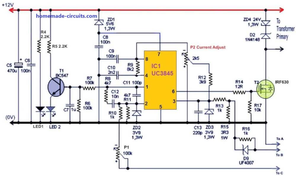
The power will not turn on if the current is less than 230V. The UC3845 control circuit results to 47% duty cycle (Max.) with the output frequency of 50 kHz.
The circuit is further powered with the help of the zener diode, which actually helps to reduce the supply voltage and even helps to shift the UVLO threshold of lower 7.9V and upper 8.5V to 13.5V and 14.1V respectively.
The source initiates the power and starts working on 14.1V. It never goes below 13.5V and further helps to protect IGBT from desaturation.
However, the original threshold of UC3845 should to set as low as possible.
The MOSFET T2 circuit controls, which helps to make Tr2 transformer work offers floating drive and galvanic isolation for the upper IGBT.
It is through the forming circuits of T3 and T4 that it helps to drive T5 and T6 of IGBT and the switch further rectifies line voltage to Tr1 power transformer.
As the output is rectified and reaches an average, it is smoothed by L1 coil and C17 capacitors. The voltage feedback is further connected from output to the pin 2 and IO1.
Furthermore, you can also set the output voltage of power supply with P1 potentiometer. There is no need for galvanic isolation of feedback.
It is because the control circuit of this adjustable SMPS is connected with the secondary SMPS and leaves no connection with the network.
The current feedback is passed through the current transformer TR3 right onto 3 pin IO1 and the overcurrent protection threshold can be set using P2.
12V input supply may be acquired from an ATX power supply
The Controller Stage Schematic
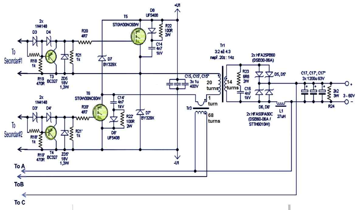
The IGBT Switching Stage
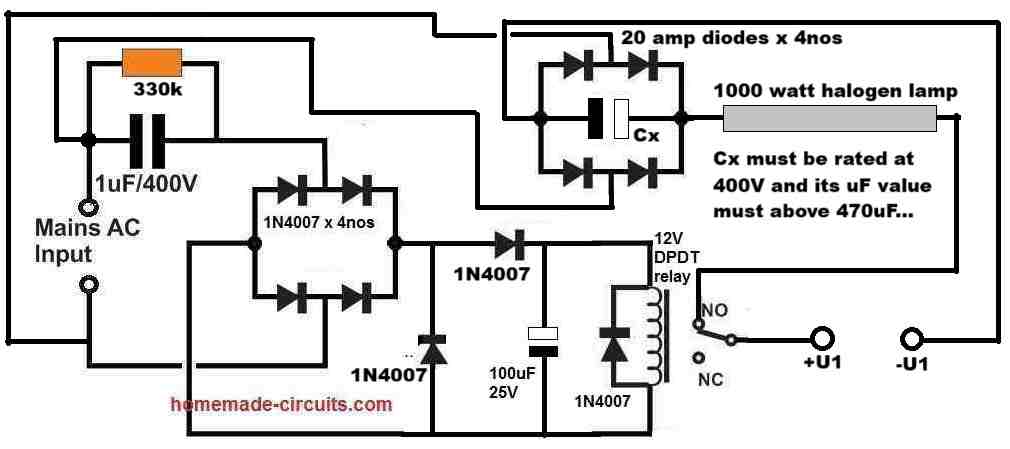
+U1 and -U1 may be derived from mains 220V input after appropriate rectification and filtration
Using Heatsink for the Semiconductors
Also, please remember to place diodes D5, D5 ', D6, D6', D7, D7 ', transistors T5 and T6 on heat sink along with the bridge.
Care should be taken to place snubbers R22 + D8 + C14, capacitors C15 and diodes D7 close to IGBT. The LED1 signals the operation of the supply and LED2 signals the error or the current mode.
The LED glows when the supply has ceased to work in voltage mode. When in voltage mode, the IO1 pin 1 is set to 2.5V else it usually has6V. LED light is an option and you may exclude the same during making.
How to Make the Inductor Transformer
Inductance: For power transformer TR1, the transformation ratio is around 3:2 and 4:3 in primary and secondary. There is also air gap in the ferrite core which is EE shaped.
If you are looking for to wind all by yourself, use a core as it is in an inverter which should size around 6.4 cm2.
The primary is of 20 turns with 20 wires with each having diameter measuring 0.5mm to 0.6mm. The secondary 14 turns with 28 diameters is also of the same measurement like that of primary. Moreover, it is also possible to create windings of copper strips.
It is important to note that application of single thick wire is not a possible idea because of the skin effect.
Now since the winding is not required, you may wind the primary one first followed by secondary. Tr2 forward gate driver transformer possesses three windings having 16 turns each.
It is by using three twisted insulated bell wires that all windings has to be wounded at once leaving any air gap at the wound of the ferrite core.
Next, taking the main power supply from AT or ATX power supply unit of a computer with the core section of around 80 to 120mm2.
The current Tr3 transformer is of 1 to 68 turn on ferrite ring and the number of turns or size is not critical here.
However, the process to orient the winding of transformers must be followed. Also you need to use double choke EMI filter.
The output coil L1 has two parallel inductors of 54uH on iron powder rings. The total inductance is finally 27uH and the coils are wounded by two magnetic copper wires of 1.7mm in diameter, which makes the total L1 cross section to approx. 9 mm2.
The output coil L1 is attached to a negative branch which results no RF voltage in the cathode of diode. This facilitates mounting the same in heat sink without any insulation.
Selecting the IGBT Specs
The max input power of the switched power supply is around 2600W and the resultant efficiency is above 90%.
In switching power supply, you can use STGW30NC60W IGBT type or you can also use other variants like STGW30NC60WD, IRG4PC50U, IRG4PC50W or IRG4PC40W.
You can also use a fast output diode having adequate current rating.
In the worst case scenario, the upper diode gets an average current of 20A while the lower diode in similar situation gets 40A.
Thus it is better to use upper diode half-current than the lower one.
For upper diode, you can use, either HFA50PA60C, STTH6010W or DSEI60-06A else two DSEI30-06A and HFA25PB60.
For lower or bottom diode you can use two HFA50PA60C, STTH6010W or DSEI60-06A else four DSEI30-06A and HFA25PB60.
It is important that the diode of the heat sink must lose 60W (approx.) and loss in IGBT may account to 50W.
However, it is quite hard to ascertain the loss of D7 since it is dependent on Tr1 property.
Moreover, the bridge loss may account to 25W. The S1 switch enables shutdown in standby mode primarily because of the frequent mains switching may not be proper, specifically when using it for laboratory.
In the standby state, the consumption is around 1W and S1 can be skipped.
If you are looking to construct a fixed voltage source of supply, it is also feasible but for the same it is better to apply transformer ratio of Tr1 for maximum efficiency, for instance, in the primary use 20 turns and in secondary use 1 turn for 3.5V – 4V.


Questions & Answers
Pl quote Variable SMPS 0-15VDC/0-100A Module (without digital display)
qty:10nos
Ph: 9821846299
Sorry, I no longer manufacture electronic kits nowadays, so can’t fulfil your order…
pasokan 12vdc untuk ic uc3845 darimana pak?
Ibrahim, You will need a separate small 220V to 12V SMPS for powering the IC.
ok terimakasih pak🙏
hello sir ,
i read this project carefully
but can’t find my answer
.
my question is where is it final output?
i see secondary side of transformer circuit show only 60 volt max
capacitor in secondary side also lower voltage
according to title output should 0 to 100 volt
i need 0 to 100 volt 10 amp supply
so i study this project
please clearfy me
sorry for bad English
Hello Naresh,
The 3-60V is the output of the circuit.
For getting 100V you can adjust the secondary 14 turns to 16 turns and increase the output range to around 100 V.
thanks for fast reply sir
one more question….
i have many smps charges they give 62 volt 15 amp
chip use in this charger sg3525
.
can i modify this charger to get 9v to 100v ,10amps
Yes, you can do it by modifying the feedback network. If that doesn’t help then you can try increasing the secondary turns of the SMPS transformer appropriately.
i understand about how to increase or decrease voltage using secondary turn increase and decrease followed by feedback manipulation
.
but i can’t understand when i rewind transformer for 100 volt then how i get 1 or 2 volt using only feedback manipulation
.
a am able to get fix voltage like 100 volt or so on
.
but 0 to 100 volt is very deficult task for me
.
please guide some
You might get an error in the output regulation depending on the feedback configuration you have used and how the SMPS is designed to respond to this feedback.
A better idea would be to fix the feedback to 100V, and then use an external buck converter to alter the output from 0 to 100V.
i think same sir
using buck converter is batter idea
but i can’t find 0 to 100 volt output 10 amps buck converter on Google
Hi Naresh,
In that case you might have to build a customized buck converter circuit for your application.
I have presented a 60V example calculation in the following article, which you can easily modify for a 100V design by replacing 60 with 100:
https://www.homemade-circuits.com/calculating-inductor-value-in-smps/
thanks sir
i will study this buck converter then comment on that post
No problem Naresh, let me know if you have any doubts or problems with the calculations.
hello sir, I want to ask about this circuit.
has it been tested?….and if I make it according to the schematic will it work?
Thank You
Hello Jorvix,
the circuit is tested and will work if done precisely as given in the diagram, without slightest of mistakes.
The user must be an expert in the field of power electronics, and must be well-versed regarding how to troubleshoot SMPS circuits.
What are the protection systems, sir?… is it just constant current?
Yes, only current control protection is provided which will handle output overloads and short circuit situations also.
hello sir, I really understand the schematic and I plan to add a soft start feature then I want a minimalist form in the circuit, can you use SMD parts?….if you can tell me which ones can use SMD parts and how many watts does SMD have?
Hello Xell,
You can connect some high value capacitor such as 100uf between pin#1 and ground of the IC for implementing the soft start.
You can definitely use SMD parts for all the components depending on the availability of the parts.
Thank you for your reply Swagatam, on the circuit the pwm part of the uc3845 is written “R9 8K2” but I can’t find out what component it is connected to because there is no resistor symbol on R9
R9 is connected between pin8 and pin4, please check the diagram now, I have corrected it accordingly…
Sir, I’ve almost finished the design and then I have a few questions…1.tr3 is it permissible to use a variation of toroid ferrite or does it have to be ee ferrite?…..and what is the estimated inductance?2. On the D7 (by329x) I have seen the data sheet of the ultrafast switching type diode, but I have difficulty finding it in my area, can it be replaced with another ultrafast diode such as the mur1560 type or something else?
Hi Xell,
I will answer your questions but before that please note that I cannot provide a guaranteed guidance for the above circuit, because as you can see it is quite a complex design, and a smallest mistake from your side can cause catastrophic results, which may be impossible for me to troubleshoot. This circuit is recommended only for the experts.
Coming to your question, TR3 can be a torroid based ferrite inductor. The details are already given in the article.
D7 can be any 10 amp 1000V fast recovery (high speed) diode.
Yes, MUR1560 should also work.
Hell sir,
thank you for sharing this diagram , it will be helpfull for me and will try to make it.
one question sir, can i add pfc(power factor coefisien) in this diagram? how to add the pfc component? thank you
Hello Del,
Please see the block diagram in the following article, it shows you how to combine a PFC with an SMPS:
https://www.homemade-circuits.com/power-factor-correction-pfc-circuit/
What’s the reason for switching both positive and negative sides of the output transformer primary? I’ve only seen either single ended switching or push´pull switching.
Thanks in advance for your answer.
I need to made a power supply ov 1000v 1 a, wih a smps cicuit, can you help me wiha sche oa a suggestio of how i can build it
an thanks
Marvi
Hi, a 1000V SMPS design is not available with me right now, if I happen to find it, will surely let you know!
Hello Swagatam,I’m planning to bulid this circuit. But the circuit diagram is not clear though, it will be good if you can share me the full circuit diagram in a single sheet. so, it will easy for me to understand and work on it.
Hello viswanathan, it is difficult to fit the entire diagram horizontally on one page, however it is easy to understand how the three diagrams are interlinked. All the relevant connection ends from the first diagram connect with the relevant wire ends of the second diagram
In between the “primary” and “secondary” connections you have to insert the transformer which is shown in the 3rd diagram.
If you are still not sure, let me know, I will try to figure it out for you.
However, please remember that this article was contributed by an external author and I do not have sufficient information about this circuit design, so if you happen to get stuck anywhere, I may not be able to help you out…
Thank you for your reply, swagatam. I get it, but i couldn’t find the EMC filter circuit diagram .
Thank you viswanathan, you are right, the input DC supply configuration to +U1 and -U1 are not shown in the above article.
I will draw it and try to update it in the above article by tomorrow.
Thank you swagatam, it will be a great help for me to built my circuit.
Hi vishwanathan, please try the following design, the EMI filter won’t be required in our initial testing, we can deal with it afterwards.:
Good day dear Swagatam. I am trying to form a pwm circuit with a 80 volt dc linear power supply and a Schmitt Trigger circuit with mosfet with a uc3825 tex.ins pwm control from 100khz to 1.5 mhz. I have several problems.
1- The 3825 when operated at 1.5 mhz gets super hot and below 900 khz it doesn’t anymore.
2- Instead of supporting the load the power supply loads the mosfets and they overheat, even though the gate voltage is slightly lower than specified.
I can only use the IRF740 mosfet circuit because it doesn’t deform the gate pulse and any other one deforms the pulse even without load.
What could I do, engineer? Can you help me?
Thank you for your attention.
Good day Antonio,
Can you please tell me how much voltage are you using for operating the IC?
Also, please let me know if the IC heats up at 1.5 MHz without its output pins connected to any MOSFET?
I will try to figure it out….
Dear Swagatam. can you design a SMPS for a Tube Amp 12 to 30 volts input and secondary 300 to 450 adjustable @ 500ma I will pay you for your trouble, Await an email soon. Thxs Peter
Hi Peter,
I think you can try the design presented at the end of the following post:
https://www.homemade-circuits.com/half-bridge-mosfet-driver-ic-irs21531d/
Let me know if you have any further questions.
Hello friend!
Very urgently, I will need 65V/23A, with fixed voltage and current.
Could you clarify a few things for me?:
1- if possible, what would be needed to work with this source at 110v and 220v?
2- for the TR1 transformer I intend to use the EE55, should I use the wire size mentioned by you in the text above?
Hello Wandows,
The above SMPS is a complex design, and i do not have the necessary expertise to deal with the specifications and the solutions associated with this design, so i am sorry, I won’t be able to help you with this circuit.
Hello , I’m trying to build the adjustable power supply . kindly help me to understand how to consider power, input current, efficiency when you have just input voltage – 240VAC and output voltage – 50VDC..
Hi, if you are considering an smps design then the calculations can be quite complex and difficult. Currently i do not have any tutorial which explains this concept comprehensively.
Dear Swagatham, I find this circuit very interesting. I am thinking of building it.
On reading carefully, I find “Care should be taken to place snubbers R22 + D8 + C14, capacitors C15 and diodes D7 close to IGBT.”
Why is it so ? Is to avoid any oscillations ?
“Next, taking the main power supply from AT or ATX power supply unit of a computer with the core section of around 80 to 120mm2.” for what ?
Transformer winding section is bit confusing.
” Now since the winding is not required, you may wind the primary one first followed by secondary.” this does not make any sense . What exactly is meant by this > Winding is not required ?
“you may wind primary one first followed by secondary ” Does it mean primary and secondary side-by-side or secondary on top of primary like ordinary transformers ?
It is better to provide
1) Core type
2) Core size
3) Wire size + nos + no of turns for primary
4) Wire size + nos + no of turns for secondary
For example :
TR1
1) Ferrite core EE
2) 6.4Cm2
3) Primary : 0.5mm or 0.6mm , 20 nos , 20 turns
4) Seconday : 28 guage (?) 20 nos , 14 turns
TR2
1) Ferrite core . Type ?
2) Core size ?
3) wire diameter ? 3 nos , 16 turns for all the 3 windins
TR3
1) Core : ferrite ring
2) Core size : not critical
3) Primary : 1 turn , diameter ?, no’s ?
4) Secondary : 68 turns , diameter ? No’s ?
“However, the process to orient the winding of transformers must be followed. Also you need to use double choke EMI filter.? what doe’s this mean ?
“use double choke EMI filter ? for what ? where ?
L1
1) Core : Iron powder ring
2) Core size ?
3) wire 1.7mm
“coils are wounded by two magnetic copper wires of 1.7mm in diameter,”
magnetic copper wire ? what is that ?
is it to make two independent chokes and connect in parallel?
“This facilitates mounting the same in heat sink without any insulation.” does it mean the choke should be mount on a heat sink ?
Dear Suresh,
The snubber network is for protecting the IGBT from spikes.
It seems there are some typos in the explanation. Regarding the ATX power supply, it could be referring to the E cores, which can be salvaged from an old ATX power supply.
This article was not written by me rather was purchased from an external author.
With great difficulty I could contact the original author for the winding details and he gave me the following detail:
“The transformer Tr1, used for switching, is created by winding on two ferrite EE cores. Each core has a 16x20mm central column, giving a total cross-section of 16x40mm, and no air gap is allowed. The primary winding has 20 turns, using 14 wires of 0.5mm diameter. The secondary winding has 6 turns of a copper strip (36 x 0.5mm).
The forward gate-drive transformer Tr2 is designed to minimize stray inductance. It has a trifilar winding with three twisted insulated wires of 0.3mm diameter, each with 14 turns. The core is made of H22 material, and the middle column has a 16mm diameter with no gaps.
The current sensing transformer Tr3 is made from an EMI suppression choke on a toroidal core. The original winding with 75 turns of 0.4mm wire serves as the secondary, and the primary has just 1 turn. It’s crucial to maintain the polarity of all transformer windings as indicated in the schematic.
The inductor L1 uses a ferrite EE core with a 16x20mm central column. It has 11 turns of a copper strip (36 x 0.5mm), and the magnetic circuit’s total air gap is 10mm, resulting in an inductance of approximately 12uH”
Dear Swagatham, This is really great and kind of you. I need to see if I can purchase the cores. It may take a few days to collect these special materials.
Thank you once again. rgds
Thank you dear Suresh,
However, please proceed with caution with this project since I do not have any expertise with the above SMPS concept and if you run into any problems then I may not be able to solve your problem.
Sure, Thank you.