A crucial safety element in cars is the reverse horn, sometimes referred to as the reverse warning device or backup alarm, which emits an auditory signal while the automobile is in reverse. The reverse horn, which is intended to improve pedestrian and occupant safety, generates a unique sound to alert others around that the vehicle is travelling in reverse.
Musical Reverse Horn with Piezo
Alright so this is a car reverse horn circuit that plays a melody when your car goes into reverse. It is built around a UM66 melody IC which generates a tune when powered. Let us break it down step by step.
What’s Inside?
We have got the:
- UM66 (Melody Generator IC) – This little guy produces the sound.
- 8050 (NPN Transistor) – Works as an amplifier to boost the signal.
- 1KΩ Resistor – Provides biasing for the transistor.
- 3-Pin Buzzer Coil (Inductor) – Helps in signal enhancement.
- Piezo Transducer – Converts the electrical signal into an actual sound.
12V DC Power Source – The circuit gets activated when the car shifts into reverse.
How It Works
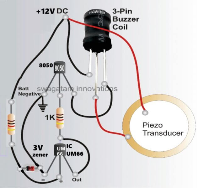
So when you shift into reverse gear, the circuit gets 3V DC from the car’s system. The UM66 melody IC starts generating a musical tone at its output pin. But here’s the thing—the signal is too weak to directly drive the buzzer.
That is where the 8050 NPN transistor steps in. It takes this weak output from the UM66 and amplifies it. The 1KΩ resistor makes sure that the transistor gets the right amount of current.
Now when the transistor turns ON then the current flows through the 3-pin inductor and the piezo transducer.
The inductor stores energy when the transistor conducts and then releases it when the transistor turns OFF, making the sound output louder. Finally the piezo transducer converts this amplified signal into a loud, melodic warning sound.
What Happens When You Reverse?
You put the car in reverse → 12V DC is supplied.
The UM66 IC starts generating a musical signal.
The 8050 transistor amplifies it.
The buzzer coil boosts the amplified the signal to extremely loud levels through the piezo.
The piezo transducer plays the tune, warning people around.
Why Use This?
It is power-efficient – Only needs 12V!
It is super simple – Uses just a few components.
It sounds pleasant and very powerful – Unlike harsh buzzers, it plays a melody.
Beeping Reverse Horn using IC 555
In the next circuit diagram I have explained how to build a simple car reverse horn circuit using a couple of IC 555 for generating the intended warning sound or tone whenever the car is travelling in reverse gear.
Circuit Description
The circuit diagram of this car reverse warning horn device is extremely simple. It is reproduced in the figure below.
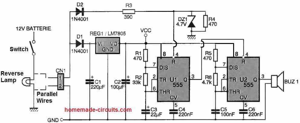
The chosen principle consists of supplying power to the warning module in parallel with the vehicle's reverse lights.
The audible signal will be obtained by exciting the piezoelectric buzzer BUZi. The U2 circuit, configured as an oscillator, will drive the buzzer.
The U2 circuit is configured as an astable multivibrator, with a frequency given by the formula 1/[0.7 x C5 x (R5 + 2 + R6)].
The operation of the U2 circuit is conditioned by its reset input (pin 4), which is derived from another NE555 circuit, the U1 circuit. The U1 circuit is responsible for periodically triggering the U2 circuit to produce a pulsed audible signal.
The operation of the U1 circuit is also conditioned by its reset input, which is derived from the input voltage, i.e., the voltage at the reverse light.
Since the input voltage is around 12Vdc, the zener diode DZ1 is used to protect the U1 circuit input. Why wasn't pin 4 of U1 connected to Vcc?
This is because, with the chosen power supply circuit, the Vcc voltage is present for a longer duration than the input voltage, due to the presence of filter capacitors.
The power consumption of the U1 and U2 circuits, along with the buzzer, is low enough for the warning device to continue functioning for a good ten seconds, which is undesirable.
Therefore, it is necessary to block the operation of the U2 oscillator when the voltage present at CN1 becomes zero.
But in that case, why not simply power the circuit directly from the voltage present at CN1?
Perhaps you know from experience that the voltage supplied by a vehicle's battery during operation varies slightly depending on the engine speed.
This voltage variation affects the frequency of an oscillator, even though in the case of the NE555 circuit, this variation remains limited.
Ultimately, the audible signal is disturbed by the variation in engine speed, which has an undesirable effect.
To overcome this issue, it is sufficient to stabilize the oscillator's power supply voltage using the REG1 regulator.
Diodes D1 and D2 protect the circuit from polarity inversion when connecting the module to the reverse light. It would be unfortunate to see the components go up in smoke on the first attempt to turn it on.
Construction
The printed circuit board to be replicated for this car reverse horn circuit is extremely simple. The track layout and the associated component layout view are shown in the following figures.
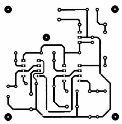
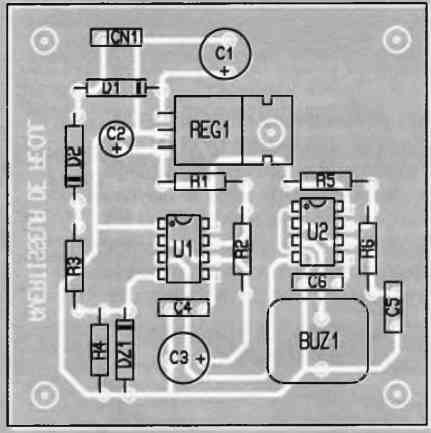
The holes for most of the pads will be drilled using a 0.8 mm diameter drill bit. However, for CN1, D1, D2, BUZ1, and REG1, you will need to drill the pads with a 1 mm diameter drill bit.
Pay attention to the orientation of D1, D2, DZ1, and, of course, U1 and U2.
It is not desirable to mount the U1 and U2 circuits on a socket (unless you choose tulip-style models) because there are plenty of vibrations in a car.
For the same reason, ensure that your soldering is done correctly to prevent the assembly from failing after some time. The REG1 regulator must be securely fastened to the printed circuit board using a small bolt.
The connection of the module should not pose major problems. Take two wires from the terminals of the reverse light (or one of the reverse lights) in your vehicle.
Identify the polarity using a voltmeter by engaging the vehicle's reverse gear (with the engine off, of course).
When engaging the reverse gear, make sure that the wires connected to the reverse light terminals do not touch each other, otherwise, you will need to replace the corresponding fuse in your vehicle.
Once the polarity of the wires is identified, connect the module in the correct orientation. You don't have to worry because the diodes D1 and D2 protect the assembly.
To secure the module in the vehicle, you can either use the designated holes for small bolts or wrap the assembly in a piece of foam and fit it into a recess in the car's trunk.
Regardless of the chosen solution to install the assembly in your vehicle, make sure that no traces on the assembly come into contact with the metal of your car.
Otherwise, watch out for blown fuses! If you want the sound signal to be well heard outside, you can also connect multiple buzzers in parallel because the output NE555 will have no difficulty driving all of them.


Questions & Answers
Its a interesting circuit and can be used in other applications,
a alternate circuit which can do the same thing . tap of the
reverse tail light and feed a 12v buzzer.
Yes, everything is available readymade from the market if you don’t prefer building them yourself…
This circuit is for those who love electronics and want to build and experiment with their own stuff.