In this post I have explained how to modify an existing button start system in motorcycles so that it's disabled as soon as the engine has started and gained the required minimum amount of RPM.
The idea was requested by Mr. Jordan
Circuit Requirements
- I just discovered your splendid site/blog with focus on education about electronics.
- May I come straight to the point of asking whether you can advise me how to do something?
- My problem is that I have a motorbike with an electric starter.
- On this model, it is a known problem that accidental pressing of the starter switch, when the engine is already running, can cause damage.
- The starter system relies on gear engagement, not a one-way clutch.
- Unfortunately, the makers did not provide any method to prevent undue starter engagement.
- I would like to add some circuitry to provide an "interlock" effect disabling the starter when the engine revs reach about 500rpm.
- I don't have ability to work this out myself, but I can do wiring and soldering of PCBs.
- The bike is a 4 stroke V-twin, with individual coils.
- Any guidance would be appreciated.
Circuit Design
The latching effect, when the engine attains around 500 RPM can be implemented through a simple IC 555 based frequency to voltage converter circuit.
I have already discussed a simple tachometer based speed controller circuit in a few of my earlier posts, the same concept could be effectively applied for the present requirement also.
The IC 555 is a wonderful little chip and there are probably countless different possible applications that could be created using this IC.
Here, in the tachometer mode the IC 555 acts like a monostable multivibrator that creates short pulses with fixed widths, depending on the predetermined values of the RC timing components..
The density or the PPM (pulse position modulation) of these pulses change depending on the frequency of the fed input signal, or the RPM data of the vehicle.
As the frequency rises the pulse density gets higher in proportion, and during lower frequencies the density gets proportionately lower.
By connecting an RC integrator it becomes possible to convert these varying PPMs into a varying equivalent DC output, which correspondingly varies based on the RPM data.
The RPM signal is easily obtained either from the CDI spark plug output, or from the pickup coil output of the vehicle.
How it Works
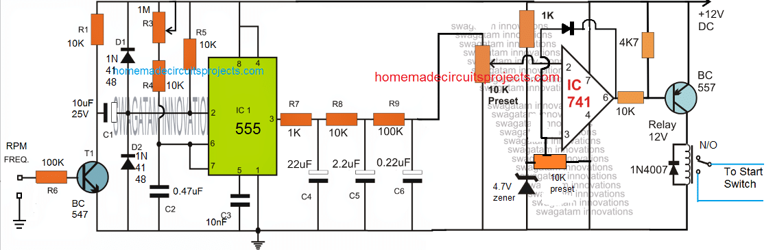
Referring to the circuit diagram of the proposed motorcycle button start lock, we can see that the design is basically divided into two stages.
The left side stage is the IC 555 based PPM generator which effectively converts the input RPM frequency signal from the vehicle's CDI into a varying pulse density output.
These varying pulse density output is fed to a 3 level RC integrator built using a few resistor and capacitor networks at pin#3 of IC 555.
The integrator smoothens the pulses from the IC555, and converts them into a steadily climbing or declining voltage, in response to the RPM frequency.
The IC 741 stage at the right side of the design is an ordinary compartaor circuit which is positioned to detect the DC levels, and activate a relay when the DC reaches a specified limit.
The 10K presets of the IC 741 are adjusted such that when the DC output corresponding to 500RPM frequency is attained from the integrator stage, pin#2 of IC 741 goes slightly higher than pin#3 potential.
When this happens, the output of the IC 741 goes low and switches ON the BJT and the relay, which in turn switches ON disconnects the starter switch from the ignition system.
The 1N4148 diode across pin#6 and pin#2 of IC741 allows the circuit to latch, so that the starter switch is held disabled permanently until the vehicle is stopped, and supply to the circuit is removed.
The pot or the preset associated with the IC 555 can be used for optimizing and achieving the best possible outcome for the RPM to DC conversion at the output of the integrator.
It is recommended that the discussed stages are tested and verified separately, and coupled together only once the stages are perfectly set and confirmed.
For any related questions please feel free to use the comment box below.


Questions & Answers
what is specific component for frequency to voltage converter and how is connected into the
circuit half a diagram is no help at all.
the section consisting R7, R8, R9, C4, C5, C6 is the frequency to voltage converter, low pass filter.
Thank you for sharing your knowledge to the ignorant like myself, I would like your input on making a led tachometer that has 2 rows of leds, one row for 100s and one row for thousands where if my engine was running at 2500 rpms it would light up 5 in one row and two in the other row, but at 1100 rpms it would only show 1 led in each row, is it possible to make it wash over like that?
You are welcome. However I could not understand your requirement.
Can you please explain the objective of the project? Why do we need two rows, and why different indications on two rows, and why measurements should decrease with increasing RPM?