A traffic light controller circuit can be used for controlling the sequential illumination of the RED, ORANGE and GREEN traffic signal lamps, by maintaining appropriate delays between the illumination sequence.
In real traffic signal light system we all have seen how the red, orange and green lamps switch ON/OFF in sequence with specific amount of time delay between each lamps.
How Traffic Signal Light Sequencing Works
Basically, the traffic lights that we see on roads and highways illuminate with a specific sequence, as I have explained below:
- To indicate that the vehicles must STOP, the red traffic lamp is illuminated.
- Then after a relatively longish delay, the red lamp is shut off, and the green lamp is illuminated, which indicates that the vehicles must start the ignition and GO.
- Next, after a relatively longish delay the green light shuts off and the orange or the amber light is turned ON.
- The orange or the amber light tells the vehicles to PROCEED WITH CAUTION and prepare to stop to the red light that follows immediately, after a relatively short delay.
In this post I have explained how to build a realistic 3 color traffic light model, which will replicate the standard traffic light sequencing operation, as seen on roads and highways.
How the Circuit Works
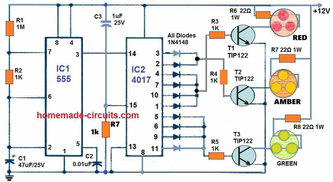
As shown in the following figure we can see an IC 4017 which is 10 stage johnsons decade counter is used for executing the red, green, orange light sequencing operation.

In one our previous articles we have already learned how the IC 4017 outputs could be used to generate sequencing high logic pulses from one pinout to the other in response to clock pulses at its pin14.
Here we employ exactly the same working principle, which could be understood from the following explanation:
For feeding clock pulses to pin14 of the IC 4017, a basic astable oscillator is required which is fulfilled using the ubiquitous IC 555.
With each clock pulse from the IC 555's pin#3 to IC 4017's pin#14, causes the output of IC 4017 to create high logic shifts from one pinout to the next in the order of: 3, 2, 4, 7, 10, 1, 5, 6, 9, 11, and back to 3.
Meaning, initially a logic high is available at pin#3 of the IC 4017. With the first clock pulse at pin14, this logic high at pin3 will jump to pin2, then with the next clock at pin14, the logic pulse will jump from pin2 to pin4 and so on.
We can see that these outputs of the IC 4017 are configured with parallel diodes in order to create extended delays on the illumination of the red and the green LED lamps.
Let's say, each pulse from IC 555 has a delay of 2 seconds (this can be changed as desired), would mean that the logic at the IC 4017 outputs would shift with a delay of 2 seconds from one pinout to the other.
Since pin3 and pin2 are tied together with diodes, the total delay across these pinouts will 2+2 = 4 seconds. This means that the orange LEDs would remain switched ON for 4 seconds.
Similarly, the diode connection across pins4,7,10,1, and pins5,6,9,11 ensure that even while the logic sequence are shifting across these pinouts the output across these pinouts keep the red and the green LEDs switched ON for 2+2+2+2 = 8 seconds.
LED Lamps
Each of the lamps (red, green, amber) are built using 3 LEDs in series. In the diagram, the each of these LEDs are 1 watt 3.3V type high bright white LEDs, which must be connected in series for making each of the lamps, as shown in the diagram.
Parts List (BOM)
- All Resistors are 1/4 watt 5% CFR, unless specified
- 1M = 1
- 1k = 5
- 22 Ohms 1 watt = 3
- Capacitors
- 47uF/25V Electrolytic = 1
- 1uF/25V Electrolytic = 1
- 0.01uF/50V Ceramic Disc = 1
- Semiconductors
- 1N4148 Diodes = 10
- TIP122 Transistors = 3
- IC 555 = 1
- IC 4017 = 1
- LEDs 3.3V, White, 300 mA, 1 watt = 9
Calculations
LED Module Calculations
Each lamp module consists of 3 LEDs in series and each LED is rated at 3.3V, 1W, 300 mA.
Total Forward Voltage (Vf):
For 3 LEDs in series:
Vf = 3 × 3.3 = 9.9V
Voltage Across Resistor (Vr):
The supply voltage is 12V so the voltage drop across the resistor:
Vr = Vsupply - Vf = 12 - 9.9 = 2.1V
Resistor Value (R):
The resistor must limit the current to 300 mA:
R = Vr / I = 2.1 / 0.3 = 7Ω
A 22Ω 1W resistor is used in the circuit likely for additional safety margin because a higher resistance will slightly reduce the current preventing LED overheating.
Resistor Power Dissipation
The power dissipation in the resistor:
Pr = Vr × I = 2.1 × 0.3 = 0.63W
A 1W resistor is used which is sufficient to handle the dissipation with a safety margin.
NE555 Timer Frequency Calculation
The NE555 timer (IC1) is configured in astable mode to generate clock pulses for IC2 (4017).
Frequency Formula for NE555:
f = 1.44 / ((R1 + 2R2) × C1)
Using the given values:
R1 = 1MΩ
R2 = 1kΩ
C1 = 47μF
Substitute:
f = 1.44 / ((1 × 10^6 + 2 × 103) × 47 × 10-6)
f ≈ 0.030 Hz
Time Period (T):
T = 1 / f ≈ 1 / 0.030 ≈ 33 seconds
This means each cycle lasts approximately 33 seconds which is divided into steps by IC2 (4017).
CD4017 Decade Counter
The CD4017 (IC2) divides the NE555 clock pulses into sequential outputs.
Each output turns ON sequentially, lighting the RED, AMBER, and GREEN LEDs through transistors (TIP122).
The diodes (1N4148) ensure only one transistor activates at a time.
Cycle Timing for Each Output:
If the NE555 produces pulses every 33 seconds, and IC2 has 10 outputs:
Toutput = T / 10 = 33 / 10 = 3.3 seconds per output.
In this configuration specific diodes group outputs to match the timing requirements of the traffic light sequence.
Transistor Selection (TIP122)
The TIP122 is a Darlington transistor with:
Max current rating: 5A (well above the 300 mA required by LEDs).
Base Resistor (R3, R4, R5): Limits current to protect the base of the TIP122.
Base Current Calculation:
The required base current (Ib) for a Darlington transistor:
Ib = Ic / β
- Where:
- Ic = 300 mA (collector current).
- β (current gain) ≈ 1000 for TIP122.
- Ib = 300mA / 1000 = 0.3mA
Base Resistor Value:
Rb = (Vin - Vbe) / Ib
- Where:
- Vin = 12V.
- Vbe ≈ 2.5V (Darlington transistor).
- Rb = (12 - 2.5) / 0.0003 ≈ 31.7kΩ
The circuit uses 1kΩ base resistors for simplicity because the TIP122 does not require precise base current due to high gain.


Questions & Answers
Can you help me ,I am having some problems in implementing the circuit.how to contact you?
This circuit is actually very basic, please tell me what problems you are facing, I will try to solve it for you quickly…
…is there a way to link either remote or sensor or timer for the changing or the light
The timer 555 is already present in the above concept.
Sensor and remote control can also be integrated, in that case the IC 555 stage can be removed and the pin#14 of the relevant trigger source can be associated with the pin#14.
…am a physics teacher and will have to design this project with my students, pls can i have a full part lists of the projects
I have added the full parts list in the above article…
please I took this idea as my project at the university and it got accepted but there is no video or real circuit photo you have uploaded to follow it and i cannot start making it
You can build the first circuit shown in the above article it will work without fail, if you need any help please let me know, I will surely guide you.
I am not an Electrical engineer or that sharp. Will this circuit work for 12 Volt lamps? Is there anything I need to change to make it work. I am building a stop light for the grandkids train set.
Yes you can replace the LEDs with 12V bulbs. The current rating of the bulbs must not exceed 1 amp. AS mentioned in the article, the direct connection of pin#15 with the ground line is incorrect, it must have a 10K resistor in between.
Your work is execllent,and l will like you to bring me up.thanks.