Within the next few years we may find all conventional capacitor-start type of ceiling fans getting replaced with BLDC ceiling fan circuits, since the concept allows the operation to be extremely efficient and save power by more than 50%.
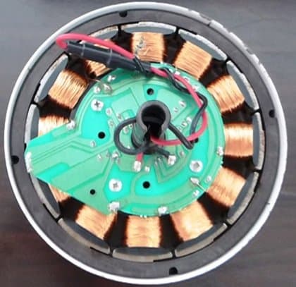
Replacing Capacitor Start Fan with BLDC Fan
Just as the traditional incandescent lamps today are almost replaced with the much efficient LED lamps, it's now time for the ceiling fans to become smarter and more efficient.
In fact making a BLDC based ceiling fan circuit may be much easier than a capacitor-start type of fan, and could be done by even by an ordinary hobbyist having basic knowledge of electronics.
What you will Need
To achieve this, you may have to acquire or make the following modules:
1) A BLDC controller circuit.
2) An SMPS for powering the BLDC controller circuit
3) An appropriately matched BLDC motor.
4) propeller or blade fitting for the motor.
Main Specifications
The BLDC controller specs can be selected as per the available BLDC motor's specs, for example if you find it comfortable procuring a 220V or 310V BLDC you could probably go for a controller design having matching specs, such as the following circuit which was posted sometime back in this website.
Compact 3-Phase IGBT Driver IC STGIPN3H60
On the other hand if a lower rated BLDC motor in the range of 12V to 50V looks easier to obtain, one could think of selecting the following alternative design, which was also posted recently in this website:
50V 3-Phase BLDC Motor Driver Circuit
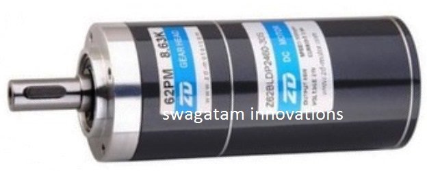
Since acquiring a 24V BLDC motor appears to be much easier than a 220V counterpart due to its easy availability in the market, we'll discus the proposed BLDC ceiling fan circuit using a 24V BLDC motor.
Let's assume we select a 24V 2 Amp BLDC for our ceiling fan, as shown in the following example, make sure it includes sensors with it:
To control this motor and apply it like a ceiling fan, we can use the 50V driver circuit link as indicated in the previous paragraph, and modify the attached diagram to suit the ceiling fan control parameters, as indicated below:
Circuit Diagram
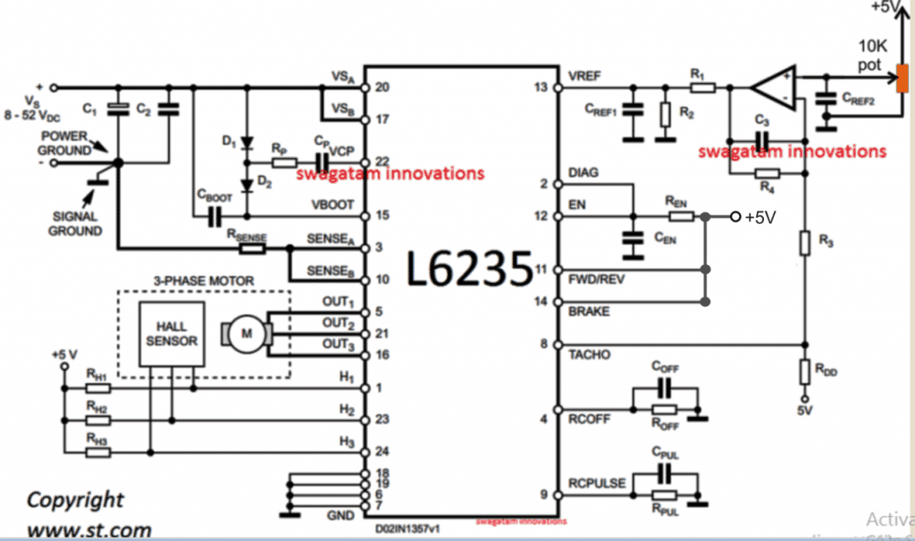
The diagram looks pretty straightforward, and you just need to connect the parts as displayed in the diagram, using a well designed PCB.
The 10K pot serves as the speed control knob for the ceiling fan.
Parts List
- C1 = 100 µF
- C2 = 100 nF
- C3 = 220 nF
- CBOOT = 220 nF
- COFF = 1 nF
- CPUL = 10 nF
- CREF1 = 33 nF
- CREF2 = 100 nF
- CEN = 5.6 nF
- CP = 10 nF
- D1 = 1N4148
- D2 = 1N4148
- Opamp = IC 741
- R1 = 5.6 K
- R2 = 1.8 K
- R3 = 4.7 K
- R4 = 1 M
- RDD = 1 K
- REN = 100 K
- RP = 100
- RSENSE = 0.3
- ROFF = 33 K
- RPUL = 47 K
- RH1, RH2, RH3 = 10 K
Power Supply:
From the above shown BLDC ceiling fan controller circuit, we can understand that the circuit will require a DC power for operating, and this may be fulfilled through any standard SMPS unit.
The best example is your laptop charger which can be effectively used for operating the proposed 24V BLDC motor, through the given controller circuit.
In case you decide building the SMPS yourself, you could perhaps try the concept explained in this 12V, 2 amp SMPS circuit.
Here the secondary winding ratio could be suitably doubled for getting the required 24V instead of the specified 12V in the design.
For the 5V supply you can use a 7805 IC based stage, and achieve the 5V requirement for the BLDC controller card.
Conclusion
The main objective of using a BLDC fan is to implement a capacitor less motor (or brushless motor) where the rotor does not carry any winding, which in turn ensures virtually zero friction and therefore extremely high efficiency compared to the normal capacitor type ceiling fan units.
You can use any BLDC for that matter, and power the DC circuit and the motor with an SMPS.
However it must be noted that motors rated with higher voltage will give higher efficiency for this particular application.
This concludes the explanation regarding the making of a simple BLDC ceiling fan circuit, if you have any related doubts let me know through your valuable comments.


Questions & Answers
Sir,
From the figure of BLDC motor, the shaft seems to be 1 inch thick. Are there suitable fan blades commercially available . Or how the fan blades can be suitably fixed for domestic use can be explained
Premila, there are many different types of BLDc motor available in the market from different companies, you can chose the one which suits your requirement, alternatively you can get an external attachment fabricated for the shaft, as per your specific needs..
how can i get repair circut which is not working
please give more info regrading all the parts and schematic of your circuit, I may try to help
I want to fit a gsm based circuit in my two wheeler to trace the location.So asimple circuit diagram may please be provided.Thanks
sorry, this kind of circuits are never simple. If you are a newcomer then I would recommend buying it readymade which will provide you the results quickly and with minimum efforts.
hi swag.please help me about all kinds of motor winding calculation,any kind that has windings.transformer and designing to desired wattages.i watched you tube,searched in any way,but i can’t find a solid foundation that i can rely on.and if you are willing to show an example of winding diagram,please do so.hope you can have one.thanx.more tutorials.
Hi Dennis, I am not so sure about motor winding, but for transformers I have a few articles published in my website which you can read below:
https://www.homemade-circuits.com/2015/07/turns-and-voltage-ratios-total-voltage.html
https://www.homemade-circuits.com/2018/02/how-to-make-transformers.html
https://www.homemade-circuits.com/2012/02/how-to-design-your-own-inverter.html
I hope this will help.
Let me know if you have further questions 🙂
hi swag.thanx for replying fast.it was useful and dependable for transformer.i just saved it and starting to study.i wish i could find also for motor rewinding calculations and parameters. hope you’re not getting tired of helping us.i always visit your site and i almost saved every circuit you made.simple yet unique, highly efficient,and very lucrative.i wish we had someone like you here in philippines.god bless!
Thank you Dennis, dedicated readers like you are my assets and I am always happy to help them.
I’ll surely try to get the details for motor winding if possible, and update it here.
Wish you all the best! God bless you!
Hi Swag, Good Day!!
I am interested in innovative ideas and predominantly focusing more on the eco-friendly environment. This article is quite useful to get the basic knowledge on the bldc motor control circuit for ceiling fan. However, it would be really helpful, if you could enhance the circuit to include the speed control and is there any efficient way to reduce the power consumption. Thanks
Thanks Manikandan, The 10K pot at top right of the schematic is for controlling speed of the motor. All BLDC drivers will essentially have a feature for the speed control.
Bro provide bldc pcb schematic diagram which can help me to repair
BLDC can be very difficult to repair because they are mostly built using SMD, and with special ICs
Actually u already gave it but parts are not available in market kindly give any online vendor which can deliver to my home
You can use any BLDC circuit for building a BLDC fan, the above is only an example, there are plenty BLDC datasheet available online to choose from.
Haii,,,what is the number of the PCB.for 220v bldc remote operated ceiling fan
Good afternoon.
has a BLDC ceiling fan control board with hall effect sensor, it has 4 4n60c mosfets. and the 4 resistors connected to the source output of these mosfets burst, and I can’t find the electrical diagram to perform the exchange. how do I find out the values of these resistors to exchange them.
Hi, those are current limiters which are actually not too critical. You can calculate them using Ohms law. R = V/I
the value of I will be the maximum tolerable limit of the MOSFeTs.
1 KW BLDC MOTOR CONTROL USE BIG FAN
Can we replace rotor in an induction motor with magnets and rewind the stator to make it Bldc, can we use the existing slots for new winding, Any known issues?
I don’t think that might be feasible since the BLDC internal structure is very different from an induction motor
Can I buy pcb for 12 v ceiling fan & what are the best price
The PCB is not available from this site, but you can search it online and check the results.
Good evening Sir. Circuit diagram required for The pcb shown in photograph.
It has only 4 3055 and one hall sensor.
Thank you.
Hi Purushottam, I am sorry, I do not have a circuit diagram of a BLDC motor using 4nos of 2N3055 transistor and a single hall effect sensor.
Hi,
Can you send the Block daigram of BLDC fan for better understand and to design perfect.
Hi, you can check out the datasheet of the IC for the full explanation and the block diagram:
https://www.st.com/resource/en/datasheet/l6235.pdf
hello sir please can you put me through on the circuit diagram of AC DC ceiling fan
Hello Mohammed, a BLDC fan is an AC/DC fan, because it can be used with an AC also through an SMPS.
I NEED HELP WITH SCHEMATIC DIAGRAM OF 12V BLDC FAN SO I CAN DESIGN PCB ACCORDING TO IT
CURRENT PCB HAS
1. Hall sensor – 120JC1
2. MOSFET – D50N06(2 nos)
3. Diode – SS24(3 nos)
4. Zener diode – 12V, 1W
5. Capacitor – 22µF 50V, 47µF 50V
6. Resistor – R7->2.4kΩ (Gate resistor)
7. Resistor – 0Ω (R2->100E,R3 R4 R5 R6->10K, R8->100E, R9->820E, R10-> 1K, R11 R12->0E)
8. Transistor- 1f (npn)(bjt)
9.F1 PTC 185
THE FAN IS GETTING STOPPED DUE TO HIGH CURRENT WHAT CAN I DO TO AVOID IT
Hi, I think you can employ the circuit design explained in the above article, it is best suitable for typical DC BLDC fans.
To ensure the driver can handle higher fan loads, you can adjust the value of the Rsense resistor apropriately.