In the realm of motor control systems, high voltage DC motors play a crucial role in numerous industrial and automotive applications. Efficiently controlling the speed of these motors while ensuring operator safety and isolating sensitive components can be a challenging task.
However, with the advent of advanced technologies, such as optocoupler motor controller power stages, achieving precise control and perfect isolation in high voltage DC motor circuits has become increasingly feasible.
This article explores a high voltage DC motor speed controller circuit that incorporates an optocoupler motor controller power stage.
By utilizing this innovative design, engineers and enthusiasts can seamlessly apply any desired high voltage to the motor section, allowing for compatibility with a wide range of high voltage motors.
Additionally, the optocoupler facilitates perfect isolation, offering enhanced safety measures and protecting sensitive components from potential electrical disturbances.
Basic Working Concept
Many low-power DC motors are machines whose armature is a permanent magnet, therefore with a fixed flux.
The rotational speed of such a motor depends practically only on the average voltage applied to the armature. By applying a continuous and constant voltage corresponding to the rated voltage of the motor, its speed will be maximum.
However, if using any device, the voltage is applied only during a period T1 and then interrupted during a period T2, it is possible to lower the average value of this square wave voltage and consequently the motor speed.
The durations T1 and T2 constitute the complete period T of a high-frequency chopping frequency that can reach several tens of kHz.
This is the whole principle of the CHOPPER, a true DC current dimmer.
We propose building such a power converter that has the peculiarity of having an optical coupling between the control part and the power stage represented by the motor.
Therefore, it will be possible to supply the motor with a higher voltage than that of the electronic control module. Using a simple potentiometer, it will be possible to vary the speed of a DC motor from 0 to 100%.
Circuit Description
The complete circuit diagram is shown in Figure 1 below. The adopted principle is very similar to that used in industrial systems.
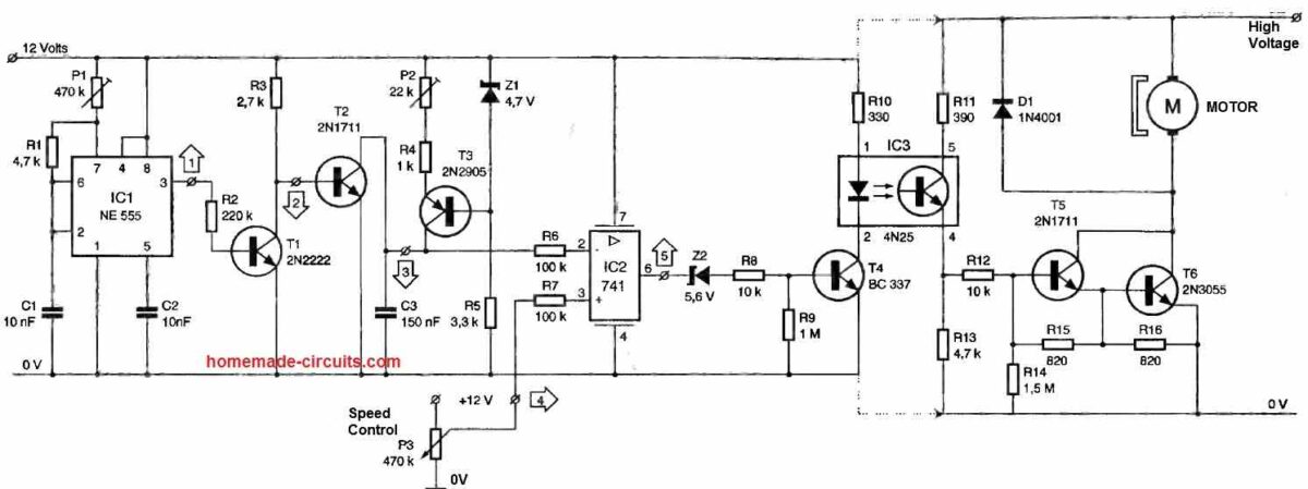
Firstly, there is a constant astable oscillator around the IC1 circuit, the famous NE555 timer that has been widely used.
On pin 3 of the IC1, we have an asymmetric rectangular signal with a frequency dependent on C1, R1, and especially the adjustable P1.
The NPN transistor T1 inverts this signal and directly controls the base of the transistor T2, which is used here as a short-circuiting device for the 150nF capacitor C3.
This capacitor is charged with a constant current thanks to the device built around the zener diode Z1. The signal at test point 3 is a linear sawtooth waveform due to the periodic and abrupt discharge of capacitor C3.
It is sent through resistor R8 to the inverting input of the operational amplifier IC2, which is used here as a voltage comparator.
This circuit also receives a DC voltage on its non-inverting input, which varies between 0 and 12V through the potentiometer P3, used to set the speed reference.
The operational amplifier, in saturation mode, delivers a complex signal on its output (test point 5), which precisely determines the value of the average output voltage, controlling the duty cycle. The circuit includes galvanic isolation and amplification.
The transistor T4 is responsible for driving the emitter diode of the optocoupler IC3, a 4N25 circuit in a DIL6 package.
The phototransistor, connected between pins 4 and 5, is responsible for implementing a Darlington stage built around T5 and T6, with the latter being a robust power transistor.
Construction
The layout of the copper traces is shown in Figure 2 and includes some wider traces that can handle the high voltage and high current required by the motor.
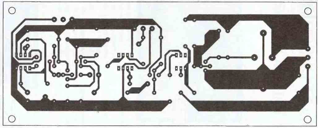
If the voltage for the motor is the same as the rest of the circuit, typically 12V, the two parts of the circuit can be connected while maintaining optical coupling.
The freewheeling diode D allows the flow of current during the periods when the transistor T6 is open.
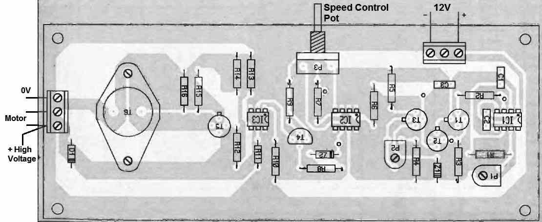
The placement of the various components should be done following the instructions in Figure 3 above, and taking care to orient the polarized components correctly.
How to Check
The adjustment should be done in the presence of a motor: the goal is to obtain a very slow speed by adjusting P3, while keeping P1 and P2 in the middle position initially.
It would be useful to connect a voltmeter to the motor terminals to observe the gradual increase in voltage as the motor speed increases.
The adjustable resistor P1 modifies the chopping frequency, and thereby the characteristic noise or whistling of the chopper.
The element P2 configures the shape and amplitude of the sawtooth waveform, which should not have a high plateau to ensure a constant speed in the mid-range of the potentiometer P3.
With a little patience, you will be able to easily fine-tune the various settings of this converter.
The Advantages of Optocoupler Motor Controller Power Stage
Perfect Isolation: One of the primary advantages of incorporating an optocoupler motor controller power stage is its ability to provide perfect isolation between the control and motor sections.
This isolation prevents any direct electrical connection, ensuring that electrical noise, transients, or faults on one side do not affect the other.
It enhances safety for operators and protects delicate control circuitry from potential damage.
Compatibility with Various High Voltage Motors: The versatility of the optocoupler motor controller power stage allows the high voltage DC motor speed controller circuit to be compatible with a wide range of high voltage motors.
By decoupling the control signals from the motor section, the circuit can be seamlessly integrated with motors of different voltage ratings, accommodating various application requirements.
Enhanced Noise Immunity: High voltage environments are susceptible to electrical noise, which can interfere with control signals and degrade motor performance.
The optocoupler's isolation capability helps mitigate this issue by reducing the impact of noise, ensuring the integrity of control signals, and maintaining stable motor operation.
Conclusion
The incorporation of an optocoupler motor controller power stage in high voltage DC motor speed control circuits offers a host of benefits.
By providing perfect isolation, this technology ensures the safety of operators and safeguards sensitive components from potential electrical disturbances.
Moreover, it enables compatibility with diverse high voltage motors, allowing for greater flexibility in motor selection.
With its enhanced noise immunity, the optocoupler motor controller power stage contributes to reliable and precise motor control in high voltage applications.



Have a question or feedback? Feel free to ask below—just make sure it relates to the post above!