In this article we investigate 3 simple yet powerful battery desulfator circuits, which can be used to effectively remove and prevent desulfation in lead acid batteries. The first method uses PWM pulses from a 555 PWM circuit using existing battery power itself, the second concept involves high voltage spikes, while the third design discusses desulfation using a 555 IC PWM based high voltage pulsed circuit.
Sulphation in lead acid batteries is quite common and a big problem because the process completely hampers the efficiency of the battery. Charging a lead acid battery through PWM method is said to initiate desulfation, helping recover battery efficiency to some levels.
What is Sulphation in Lead Acid Batteries
Sulphation is a process where the sulfuric acid present inside lead acid batteries react with the plates overtime to form layers of white powder like substance over the plates.
This layer deposit seriously deteriorates the chemical actions inside the battery while charging or discharging making the battery inefficient with its power delivering capabilities.
Normally this happens when the battery is not being used for long periods and the charging, discharging processes are not done very frequently.
Unfortunately there's no effective way of tackling this problem, however it has been researched that the jammed sulphur deposits over an effected battery may be broken down to some extent by subjecting the battery to high current bursts while charging it.
These high current charging pulses should be well optimized through some control circuit and should be diagnosed carefully while implementing the process.
Audio/Video Representation
1) Using High Amplitude Pulsed Current from 555 Boost Circuit
We are not going to offer you a solution that will magically solve all the problems with lead batteries. However, the battery desulfator that we will describe in the following lines has proven its effectiveness, mainly in the United States for now, and the measurements we have been able to make on our model have been very promising. As it costs less than twenty euros, which is negligible compared to the price of a new high-quality battery, why not try it out and see for yourself?
Understanding Battery Chemistry
As you may know, a lead-acid battery involves a chemical reaction that can be written as follows during the discharge process:
Pb + 2H2SO4 + PbO2 -> PbSO4 + 2H2O + PbSO4
In other words, the porous lead of one electrode and the porous lead dioxide of the other are transformed, in contact with sulfuric acid, into lead sulfate and water.
Conversely, during charging, the chemical reaction that occurs is as follows:
PbSO4 + 2H2O + PbSO4 -> Pb + 2H2SO4 + PbO2
In other words, lead sulfate and water are transformed, under the effect of electric current, into lead, lead dioxide, and sulfuric acid.
The reaction is theoretically perfectly reversible, and that is why a battery of this type can be charged and discharged many times.
Unfortunately, over time and especially due to incomplete or poorly done recharges, the "reverse" reaction, i.e., the one that transforms lead sulfate into lead, is incomplete and leaves lead sulfate present on the surface of the battery electrodes or plates.
The phenomenon is unfortunately cumulative because, as this lead sulfate is a poor conductor, it tends to thicken where it has started to deposit, which only worsens the problem.
When the sulfation of a battery has reached a sufficient level, no traditional recharge process can overcome it.
Indeed, due to the poor conductivity of lead sulfate, the internal resistance of the battery increases, reducing its charging current and therefore the effectiveness of the charging chemical reaction, leaving even more lead sulfate present on the electrodes.
The resistance of the battery eventually becomes so high that it cannot hold a charge, meaning it can no longer supply significant current due to its excessively high internal resistance.
The Working Concept
This phenomenon has been known for a long time, and there is a chemical process that can be used to eliminate lead sulfate from a battery before it's too late.
However, it's delicate to implement and relatively dangerous due to the chemicals involved. In fact, the battery must be emptied of its electrolyte (corrosive!) to fill it with the cleaning product (also corrosive), and once this operation is complete, the battery must be refilled with fresh electrolyte.
The approach we propose is different and comes from various studies conducted in the United States on the influence of high-amplitude pulsed currents applied to a lead-acid battery.
According to these studies, and provided that very brief but high-amplitude impulses are applied to the battery, the lead sulfate crystals would gradually be broken down by the resulting ionic agitation occurring at the level of the plates and electrolyte of the battery.
This phenomenon is very slow, but since it can be achieved by simple electrical means, this process doesn't pose any particular problems as no manipulation is necessary on the battery being treated.
Circuit Description
The diagram that we propose is widespread on the internet on the other side of the Atlantic and, as far as we could verify, is attributed to Alastair Ocup. As you can see from in the following figure, it is relatively simple and has many similarities with a boost-type switching power supply.
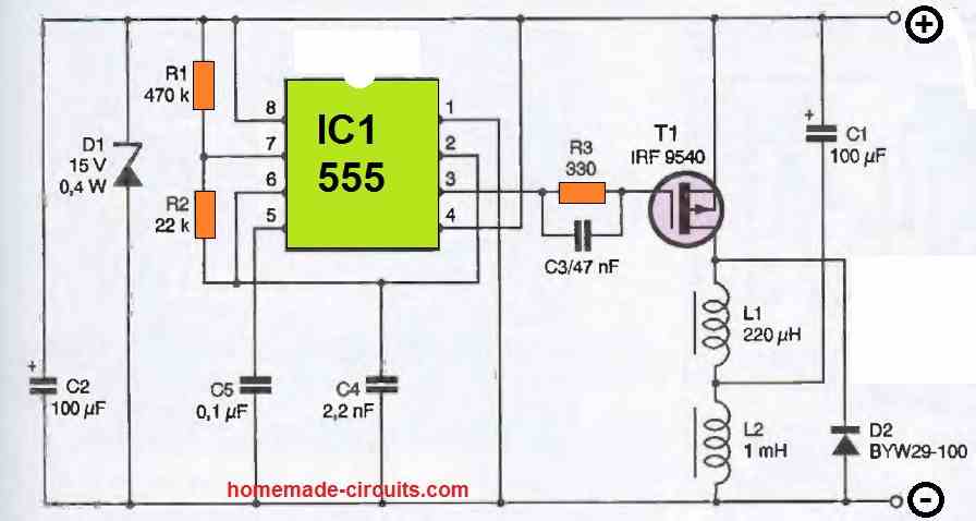
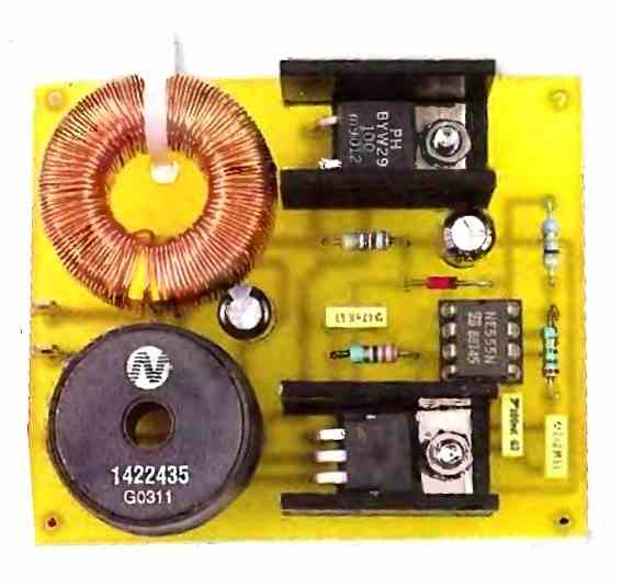
IC, which is nothing other than a classic 555, is configured as an astable oscillator operating at a frequency of around kHz. It produces very short duration pulses on its output available at pin 3.
When the level of these pulses blocks T1, capacitor C1 charges to the value of the battery voltage via inductor L2.
When T1 is made conductive, which only lasts for a brief moment due to the duty cycle of the pulses produced by IC1, capacitor C1 discharges abruptly across T1 and L1 since it is almost short-circuited by these components.
As soon as T1 is blocked again, the current generated by this discharge cannot abruptly cancel due to the presence of inductor L1. It is therefore sent to the battery via diode D2.
If capacitor C1 is of good quality and if the connection between the circuit and the battery is short and made of a suitable diameter wire, a current peak of the order of 5 to 10A can be obtained with a moderately sulfated battery.
Given the operating frequency of the 555 and the duty cycle of the signals it produces, the circuit's consumption remains relatively low and does not exceed an average value of 40mA.
2) Using High Voltage Pulse
The configuration detailed below provides the most up-to-date methods of desulfating lead-acid batteries. It is a circuit which routinely supplies quick yet intense pulses to the battery, while discharging the battery marginally between the pulses.
This technique, as much as recognized right now, is the best way to knock of undesirable build up of sulphate crystals and to bring back the battery plates into a good condition.
Because the voltage necessary for the high voltage pulses comes from the battery itself (this might appear a little bizarre initially, however the discharge of the battery is likewise a part of this technique), it is advised to hook up a charger in parallel with the battery and desulfator once the battery has not much capacity remaining.
Pulse generator
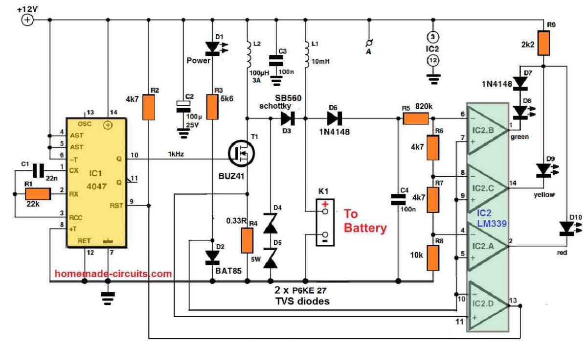
It could be noticed in the circuit diagram that the parts needed for the desulphator tend to be extremely humble. The circuit consists of a couple of stages: a high voltage generator constructed using IC1, IC2d and T1, that generates the charging pulses, and an indicator circuit which involves not more than 3 op amps (IC2a, b, c) and three LEDs, that indicate exactly what condition the battery is in.
Let’s go through the pulse generator initially. Just like the other parts of the circuit, its supply voltage is obtained from the battery itself through K1. Although we’re discussing the supply voltage, this must have a pretty consistent voltage and should be devoid of any spikes (except those produced by the circuit itself).
Inductor L1 works like a suppressor, and is included in order to eliminate undesirable voltage spikes, along with C2 and C3 which work like smoothing capacitors.
LED D1 illuminates as soon as the supply voltage is switched ON. To proceed with the pulse generator, IC1 (a 4047) produces a square wave having a frequency of 1 kHz and a duty cycle which typically is 50 PERCENT. When the Q output of IC1 turns high, FET T1 switches ON. This results in a (discharge) current to move through the battery by means of L2, that boosts linearly until the voltage across R4 is approximately 0.35 V; the current can now be around 1 A.
At this instant comparator IC2d changes state, triggering IC1 to be reset and T1 to become switched off. The stashed magnetic energy inside L2 now gets converted to a voltage spike, which is inflicted to the battery through D3. How big the spike is can be determined by the condition of the battery.
If the battery is in a decent condition and its internal resistance is rather small, in that case the spike voltage level may also be reduced (under 15 V). In case the battery has a high internal resistance then the peak level of the spike could be as huge as 50 V. Its highest magnitude will be restricted and equal to the value of the two series connected zener diodes, D4 and D5.
LED Indicators
Considering that the health of the battery could be dependent on how big the charging pulses are, we have included a straightforward LED circuit which indicates the optimum value of the pulses. The 3 comparators IC2a-c evaluate the peak value inside C4 and changeover at voltages of 15, 20 and 30 V correspondingly.
Therefore in case the battery is in a reasonably good shape, the green LED (D8) illuminates, with a under-performing battery, the yellow LED (D9) lights up, and with an incredibly bad battery the red LED (D10) glows.
We have an information that needs to be pointed out regarding the indicator circuit: in order to prevent all three LEDs from illuminating simultaneously in response to a high peak voltage, they are attached in parallel to a single common series resistor (R9).
Since the red LED carries a smaller voltage drop compared to yellow LED, they may in no way illuminate together. But the yellow and green LEDs have got a identical voltage drop, so a similar technique will not do the job here, which explains why the green LED comes with an normal diode (D7), hooked up in series with it.
You will find three alternative methods through which the desulfator may be used. The first is to apply it within an existing system (inside a car as an example) to avoid sulphation from taking place inside a battery having minimum sulphation.
The advanced desulfator circuit is built-in with the system by hooking it up straight to the battery using shortest possible cabling. Because the circuit could be kept connected forever, absolutely nothing more needs to be done.
The current consumption is approximately 20 mA, therefore the battery might discharge in case it is not charged up from time to time. Recovery of batteries which have previously sulphated can be carried out in a couple of techniques. The first method would be to charge the battery, eliminate the charger and after that hook up the desulfator circuit.
Since the power for the charging pulses is derived directly from the battery itself, it is going to gradually discharge. This technique needs to be observed carefully because a completely discharged battery must be recharged quickly.
Most likely in real life many charge/discharge cycles will probably be necessary before a terribly sulphated battery could be restored to life. Since the approach described above needs a great deal of attention and has a danger that the battery could be left in a discharged condition unnecessarily (which can be extremely harmful to a lead acid battery!), another method can be perhaps much better.
The battery is coupled to the desulfator circuit, using a trickle charger hooked up in parallel. This implies, no chargers must be integrated that supply a current of 7 A or higher, yet one that provides a optimum of 1 or 2 A. This could be left coupled to the battery endlessly with no issues.
3) Using Simple PWM Circuit
This circuit diagram shows a simple 12V battery desulfator circuit made using a IC 555 timer and an inductor coil. Over time lead acid batteries get sulfated, meaning hard lead sulfate crystals deposit on the plates and reduce battery capacity.
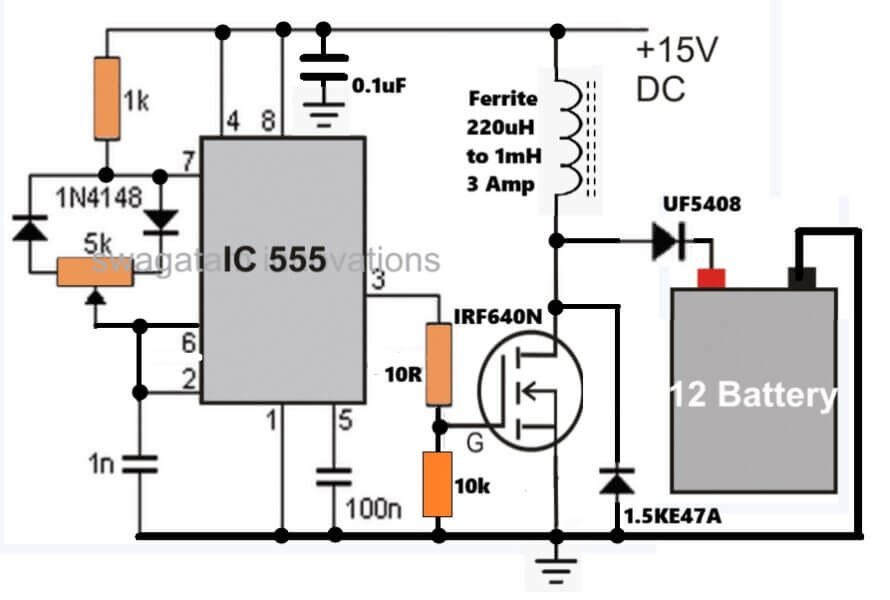
This circuit generates sharp high voltage pulses to break down those chemical crystals and restore the battery.
In this circuit, IC 555 is wired in astable multivibrator mode. The 1k resistor, 5k preset pot, two 1N4148 diodes and 1nF capacitor connected to pins 2, 6, and 7 decide the switching frequency and duty cycle.
By adjusting the 5k pot you can change the pulse width and frequency.
The output from pin 3 of the 555 IC goes to the gate of the IRF640N MOSFET through a 10 ohm gate resistor. The 10k resistor from gate to ground ensures the MOSFET turns off cleanly without floating.
When the 555 output goes high, then IRF640N MOSFET switches ON. Current flows from the +15V DC supply, passes through the ferrite inductor coil (220uH to 1mH, 3 Amp rating), and goes through the MOSFET to ground. During this ON time, electrical energy is stored inside the magnetic field of the inductor.
When the 555 output goes low, then MOSFET suddenly turns OFF. The magnetic field in the inductor collapses rapidly, creating a very strong high voltage back EMF pulse at the junction between the coil and MOSFET drain.
Because this voltage spike is much higher than 12V, it forward biases the UF5408 ultra fast recovery diode. The diode directs this sharp high voltage pulse directly into the positive terminal of the 12V battery.
To protect the MOSFET from getting damaged by unabsorbed high voltage spikes if the battery gets disconnected or has high internal resistance, a 1.5KE47A TVS diode is connected across the MOSFET drain to ground. If the voltage spike exceeds around 47V, the TVS diode clamps the peak voltage safely, protecting the IRF640N from breakdown.
This repeated high voltage pulsing breaks the hard sulfate layer on the battery plates back into the electrolyte, improving battery charging and extending its working life.
Calculations
INDUCTOR ENERGY STORAGE FORMULA
E = 0.5 * L * (I^2)
Where:
- E = Stored energy in Joules (J)
- L = Inductance in Henries (H)
- I = Peak current through the inductor in Amperes (A)
This formula shows how much energy the ferrite coil stores during the MOSFET ON time. Higher inductance and higher peak current result in more energy stored to deliver stronger pulses to the battery.
INDUCTOR BACK-EMF VOLTAGE FORMULA
V = L * (dI / dt)
Where:
- V = Peak back-EMF voltage spike generated across the coil
- L = Inductance in Henries (H)
- dI = Change in current (Peak Current - 0)
- dt = MOSFET turn-OFF time in seconds
This equation tells why fast switching is critical. When the MOSFET turns off very quickly (dt is extremely small), then rate of current change (dI / dt) becomes huge, generating a high-voltage spike (V) to break sulfation.
555 ASTABLE FREQUENCY FORMULA
f = 1.44 / ((R1 + 2*R2) * C)
Where:
- f = Output switching frequency in Hertz (Hz)
- R1 = Resistance between Vcc and Pin 7 (1k ohm)
- R2 = Resistance of the 5k pot branch between Pin 7 and Pins 2/6
- C = Timing capacitor value on Pins 2/6 (1nF or 0.000000001 Farad)
This formula gives the frequency of the pulse generator. Adjusting the 5k pot changes R2 which alters the pulse repetition rate.
MOSFET ON-TIME FORMULA (DUTY CYCLE CONTROL)
t_ON = 0.693 * R_A * C
Where:
- t_ON = Time duration the MOSFET stays switched ON (charging the coil)
- R_A = Resistance in the charge path (1k + active portion of 5k pot via diode)
- C = Timing capacitor (1nF)


Questions & Answers
Good day, Swagatam,
I didn't get nF capacitors (not available at the shop I went to), I bought a 1 microF and a 100 microF. If I substitute these into the circuit, how will it affect the output?
Thanks,
Satyam.
Good day Satyam,
The circuit needs to be operated with high frequency so a 1uF or 100uF will not work.
1nf = 0.1uF, so can try other closer values like 0.22uF etc. or any value between 0.01uF to 0.1uF will also do.
oops, correction: 1nF = 0.001uF
better use a 680pF for pin6/2 and 103 or 0.01uF for pin5
Good day,
Thanks for your quick response. I've built the circuit with the components that I described, however I'll keep looking for the correct capacitors. (I got some surface-mounted caps yesterday, but destroyed them trying to install them.)
I suspected that my frequency would be affected. Using f= 1/(0.693 x C x (R1 + 2R2)), the frequency of my circuit would be somewhere around 300 Hz, whereas your design is for 300 kHz. Does that sound about right?
At any rate, I'm using it on a number of car batteries where I suspect sulphation. Will come back & update when I replace the caps, or with results.
Best regards.
Higher frequency would produce better effects according to me, however the pwm pulses would finally decide the optimization rate.
Swagatam:
Excellent circuit, I'm about to try arm. I'd appreciate if you tell me regularly cnveniente a zener and 100 ohm resistor voltage to the 555 and ensure it does not overheat.
Thank you for your attention
thanks electronica,
the IC can work safely with upto 15V, yet for extra stabilization you may use a 7805 IC for it.
Swagatam:
Swagatam:
Thanks for your reply and recommendation. If working at 555 with 5 volts regulated from 7805, the oscillation frequency is not affected?
Are pleased to greet and congratulate again the excellent circuits published.
Thanks Electronica,
yes it will not be affected.
Swagatam:
Very nice, I appreciate your attention to my queries. Best wishes from Guatemala.
Hugo
You are welcome Hugo!
Hi Swagatam, I have installed automatic voltage stabliser for home supply,
the only problem is, when it starts, initialy it supply high volts(300 ) for less den 1 sec. den it functions well..
Pls let me know what is the problem n how can i fix it..
Hi Nawnit,
You will need to add a delay ON timer at the output of your stabilizer as shown in the following link, a similar situation has been addressed at the bottom of the article.
https://www.homemade-circuits.com/2013/02/make-this-simple-delay-on-circuit.html
Thanks buddy,
will it work fine upto 4 kw load?
You will have to select the relay appropriately, I think a 30 amp relay would do the job.
Thanks Swagat,
sorry for one more problem,
I inspected the stablizer, it has 24 volts relays, so i need to operate the "delay on" circuit on 24 volts instead 12 volts.
What modification i need?
Thanks
You will have to use a 24V relay in the circuit, that's all, no other change would be required.
The 24v supply for the circuit can be derived from the stabilizer board itself.
Thanks Swagat,
Tryed smthing diffrnt with the stablizer that i must share wid u.
There are 5 taps in auto transformer, 1st n 3rd tap has been used as input with a relay control and rest for output wid 2 more relays.
I inspected the 1st relay status at power on, it was making 1st tap as as input for 1 sec then change it to 3rd tap as input, so there was high volt at power on.
I interchanged 1st and 3rd tap input with relay.
Now its working good .
But m not sure if it will be failed for high voltage input. Vl try to make a diagram of switching.
Please comment.
It's difficult to guess how it will do with high or low voltage condition, we can't say without practical testing, let's see…
Hi Swagat,
I need a signal strength meter for direct to home disc alignment at roof.
Can it be made simply at home with transistor and led.
Thanks
Hi Nawnit,
UHF Signal meters are complex devices, not within my reach.
Thanks!
The negative will go to the rail which is connected to pin#1 of the IC
Hi Swagatam, your circuits are incredibly practical. Thanks for sharing and explaining.
I am a bit confused as I read the thread as I saw reference to a 100K pot and L1 inductor but the circuit above for PWM 555 pulser does not show these. What am I missing ?
2.bp.blogspot.com/-L9UBEjJp8XU/UUQLd8oW6YI/AAAAAAAADkk/FlaSh6PwIos/s1600/battery+desulfator+circuit.png
Sean
Thank you Sean,
Actually the circuit has gone through many changes since it was first posted, so please ignore the previous comments as those are with reference to the previous diagram which had quite a few flaws.
The present design looks to be easier and viable.
Thanks for your clarification. I was curious about the use of the inductor (i.e. collapsing magnetic field/pulse, etc).
Anyhow, I will try this circuit out as its simple enough to make. I would like to try to revive some large capacity (100AH) NiMh batteries I have pulsing with high current. I am hoping the technique will lower the internal resistance of the batteries even though the chemistry is different (i.e. they don't sulphate).
I wanted to keep it simple, so I eliminated the inductor part, I hope it works for you….:)
Hi Swagatam
Finally have parts to make the pwm but looking for a hi current supply.
It occurred to me that lead acid batteries will not sink as much current as it starts to get full. Does the circuit take this into consideration ?
When the transistor is on, is it essentially grounding the battery ?
When it is off, is there any ringing without an inductor ?
Sean
Hi Sean,
If the voltage is set at some higher level then that will force the battery to sink the current which in turn will hopefully initiate the desulfation process.
Here you can try with a 15V DC, current may be equal to the AH level of the battery and the pot set to provide short pulses.
When the transistor is ON, it connects the negative of the battery to the negative of the power supply completing the circuit for the battery so that it receives the required charging pulse.
No, there won't be any ringing effect due to the absence of an inductor.
hi Swagatam,
Thanks again for your reply. How do I limit the current ?
I planned on using an old server power supply or rewinding the secondary of a microwave transformer. Won't the circuit try to pull all the current it can unless its limited ?
Sean
Hi Sean,
The circuit will not draw anything above 5mA, as long as the voltage does not exceed 15/16V mark, above this anyway the IC555 would get damaged, so I don't think any current control for the circuit would be required.
Hi Swagatam, I think you mis-understood my question.
With your circuit you recommend limiting the current to the battery initially to 1C. so if I have a 40AH battery, I should limit the pulse current to 40AH. I was asking how I could do this since I don't have a power supply with a current limit. I am thinking of making a power supply by stepping down 240VAC to 15VAC and rectifying it. But this will not be limited. Is there a clever way to control the max current the battery draws ?
Hi Sean,
You can select a transformer rated at around 20 to 30 amps, that will itself take care of the current…actually the current is not a critical value, anything higher than the normal charging method can be employed, and expected to work here.
Thanks again Swagatam, will update the thread with my results.
btw, I read somewhere (maybe here..) that the high current pulse may burn out shorted cells restoring even batteries that are considered unrepairable.
Hi Sean,
Then that would be an added feature of this design.
Looking forward to your updates…best wishes!
i am very proude of you . how can i indicate this circuit is working after design
keep a voltmeter attached with the battry, if the voltage increases gradually within 4 hrs means it's working.
please ignore these initial comments, the diagram has been modified and updated differently, so these comments have no relevance with the present diagram.
Hi Swagatam
I have read some of above posts talking about an inductor L1. Where is that inductor, I can't see it in the circuit or any reference in your article?
By the way, I am working on a trickle charge desulfator. I am considering to integrate a circuit to measure battery's internal resistance (BIR). There are a few BIR measuring circuits on the net but, they need to take occasional measurement manually. Here are two of them:
https://dl.dropboxusercontent.com/u/20969135/internal-resistance-tester-for-batteries-2.jpg
https://dl.dropboxusercontent.com/u/20969135/accutest.jpg
My idea is to have three-LED indication……..the red LED to indicate high resistance, yellow to indicate medium and green for very low resistance. The BIR circuit will operate in parallel with the desulfator circuit. The illumination of the green LED would indicate that the battery has been desulfated, now it is ready to use.
A relay could be used to connect the BIR circuit to the battery periodically to check the status. A latch can be deployed to keep the indicator LED on but, I just cannot sort out how to get the output on LED as the output is just 5-50mV.
Can you please help me in this regard? If required, I can send you the links of the sites to have the description of those circuits.
Hi Abu-Hafss,
In the original design I had used an inductor but later found that it could be avoided and came up with the present design , the inductor related comments that you see were posted with reference to the earlier design
A BIR could be a very useful ad-on.
50mV can be amplified by using a opamp may be. What do you think?
Hi Swagatam
I came across a desulfator circuit which, apart from the regular desulfation process, also shorts momentarily battery terminals as shown here:
https://dl.dropboxusercontent.com/u/20969135/Desulfation.gif
I want to know, couldn't the signal from the 555 pin#3 be directly fed to the gate of the mosfet (point A) or at point B?
Hi Abu-Hafss,
How does this circuit desulfate…is it by charging and shorting the battery alternately? I could not understand the concept.
Hi Swagatam 🙂
One complete cycle includes 3 steps:
1) 15 sec pulse charging
2) 1 sec delay for settling
3) 100ms shorting battery terminals
I am just curious about the driving of the mosfet as I asked in my previous post.
Hi Abu-Hafss 🙂 how are these three steps implemented because i can see only one active input from the IC 555.
I wanted to know the relevance of the transistor stages for answering your question correctly.
Normally we know that a mosfet gate can be integrated with any IC output may it be a 555, a cmos or a opamp, as long as the voltage is below 15V
Hi Swagatam
Since I was focusing only on the mosfet so I didn't gave you the details of the other sections.
As mentioned earlier, one cycle consists of mainly 3 steps + 1 step to monitor battery voltage. Each step is controlled by a 555 and another 555 is controlling all these 4 ICs (the entire cycle). If you want to have a look at the circuit, here it is.
https://dl.dropboxusercontent.com/u/20969135/Desulfator%204-stage.gif
I am sorry, that is maximum available resolution of the picture.
Now, I repeat my question in other way. If the mosfet can be driven directly by the 555, why the author deployed 0.8A transistors to drive the mosfet. You can find them at the top-right corner. I haven't linked the website as per your general instruction however, if you want to see the circuit description I can send you the link.
Hi Abu-afss,
It could be for allowing the mosfet to conduct and restrict correctly, especially the use of the push-pull (PNP/NPN) stage which ensures safe charge/discharge of the internal cap of the mosfet, because as we all know how sensitive these mosfets can be at times.
Hello Swagatam,
I would like to build a hi/lo adjustable relay/contactor.
Say ….12v on 13.5 off
I could then put it in series with any charger.
It would be great for maintenance and prevent over charging.
A variant of this could also kick in a discharge cycle.
This would be good for desulfating.
Do you have a design lik this?
Yours
Carl
Hello Carl,
Please see the last diagram in the following link, it'll fit your need well:
https://www.homemade-circuits.com/2011/12/how-to-make-simple-low-battery-voltage.html
The second relay shown is not relevant, you may remove it.