The following article provides a simple yet very decent solution for driving powerful LEDs rated at 3 watt or 5 watt.
Circuit Objective
These 3 watt 5 watt and similar high watt LEDs are able to produce highly intense and powerful light outputs, however these are extremely vulnerable too with their operating parameter. I have explained more how to operate these devices very safely using a simple power supply.
We have seen quite many power supply and driver circuits in this blog using the IC LM338, that's because this particular device is so versatile with power regulation and control functions.
The same IC yet again takes the center stage in this application too. Here the IC LM338 has been configured in its standard mode and it perfectly executes the expected current as well as voltage regulations for driving a 3 watt or a 5 watt LED.
Circuit Operation
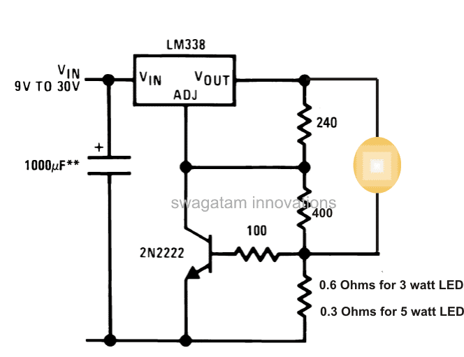
As shown in the circuit diagram below, in its standard mode the resistor 240 ohms is a regular placement, and the next resistor connected to it is the one which decides the voltage at the output of the IC. Here it has been calculated and set for producing around 3.3V at the output, which is the optimal voltage value for driving all types of white LEDs.
However the IC itself cannot control the current and normally would allow about 5 amp at the output.
We can see that the IC is associated with an additional active component which is the transistor connected to its ADJ pin.
The transistor here is employed solely for controlling the current at the output to the specified limits.
The resistor across ground and base decides how much current would be allowed to the output.
As indicated in the diagram, 0.6 ohms will pass about 1 amp maximum current which becomes suitable for driving a 3 watt led safely, and if a 5 watt LED needs to be driven safely, this resistor must be replaced with a 0.3 Ohms, which will allow a maximum of 2 amps of current.
The input to the IC can be derived from a standard transformer bridge capacitor power supply or from a suitably rated battery supply.
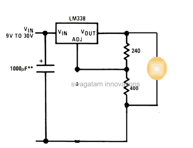
In fact, the transistor and the associated base/emitter resistors are absolutely not required, because once the voltage is set to precise 3.3V, the current would automatically get adjusted as per the LEDs specs.
So the correct circuit should be as given below:
Update:
The above suggestion is not recommended if the ambient temperature is above 25 degrees Celsius. Therefore users are requested to go with the first universal design using the BC547 as the current limiter stage, for enabling the intended current control function.
LED Driver Request
The following request for a customized 9 watt LED driver with constant current was requested by one of the avid readers of this blog
We need constant current LED driver. Supply in put is 11.0 vTO 15.0 vdcOut put required is constant current 1400 mA, 8.4VDC. The Load is 3 White Power LEDs, having Vf - 2..7 to 2.8V. This cluster will operate in flashing (Blinking mode). The circuit should have utmost high reliability, minimal number of components. We were using ONSEMI Linear LED Driver NSI 50350AST3G, (qty. 4 nos. connected in parallel)which is now not available Can you please suggest us some suitable Part or Circuit?
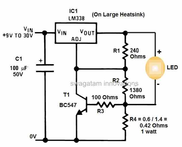
The following circuit diagram was suggested for the above application:




Questions & Answers
Hii sir
I want to make same dc to dc circuit but with 3 led of 3v, 750mA , all three in series.
Hi Naveen,
You can use the following calculator to fix the voltage for your 3 LEDs:
https://www.homemade-circuits.com/lm317-lm338-lm396-calculator-software/
The voltage must not exceed 9V at the output across the 3 series LEDs.
For the current sense resistor using the following formula:
R = 0.6 / 0.75 = 0.8 ohms
power = 0.6 x 0.75 = 0.27 watts or simply 1/2 watt
Thank you so much sir.
You are welcome naveen…
Can you help? I need to light from inside a box with a glass cover above using (I think) a small LED Mini Bulb Diode lamp (3W Warm White) that is powered by a rechargeable 12v (?) Lithium battery. I need to know which components (drivers?) I need plus a wiring diagram. Much appreciated if you can resolve.
What is the voltage rating of the LED?
How can I extend this for 10 watt
Please provide the voltage spec of the LED, I will try to solve it.
Design a constant current LED driver of 5watts.
Hi Sir,
I appreciate your work, i always visiting your website for learn something new.
There is a driver (mr16 led driver) on internet, i want to know how can we build it own. It work with 3w led input of 12v dc. Please check out the driver and make a article on it.
Thank you ????
Thank you Rohit, M16 LEDs are just like any other power LED, enclosed inside a multifaceted reflector (MR). So these LED do not require any special driver rather can be operated by any other LED driver which satisfies the exact voltage and current specifications of the LED, therefore if you know the V and I specs of the LED you can drive it with any SMPS having matching specs and current control feature.
Yes you make it as explained in my above reply.
I want to have glow a led lamp with the help of a power bank of 5v dc supply and usb
Hi Swag,
Do you any circuit with a 10W LED?
Hi Nelio, do you want an LM338 based circuit?
Hi,
One possibility. But if you have another, you are welcome.
The LM338 actually works like a current limiter, which can be also implemented through transistors. If you have a suitable power source from an SMPS or transformer then you can try any of these current limiters, as explained in the following article:
2 Best Current Limiter Circuits Explained
Hi Swagatam,
In the 1st circuit, what are the power ratting for the 0.6 and 0.3 ohm resistor?
Best Regards.
Hi Nelio, it can be calculated using the formula:
W = 0.6 x Max LED current limit
Can i use this circuit with 6 volt 4.5ah battery as input with 3 watt led 3 or 4 numbers in parallel, or can u suggest me a voltage regulator circuit
The first circuit can be used for your specific purpose.
Sir where is the link
Which link are you referring to?
Ok sir, thank you. How to calculate the resistance required?
You can replace the 400 ohms with a 4k7 preset and adjust it to get a precise 3.3V output for the LED.
The lower vertical resistor can be calculated using the formula:
R = 0.6 / LED max current
Thank u. Working fine.
Hi Swagatam, Please let me know if I can use this 3w LED circuit, in parallel to light up 12 LEDs from a single source of 15amp 12v power adapter. Will using the capacitor for each branch make it risky?
Hi Anish, you can use the single supply for all the LEDs, but you will have to incorporate individual current limiters for each of the LEDs. You can use a LM317 based current limiter as explained in the following ost for each of the LEDs separately:
https://www.homemade-circuits.com/universal-high-watt-led-current-limiter/
I already have 12nos LM338 with me. How do I use these instead of the 317s for each of the 12 LEDs (3W each). What are resistors to be used and the point where they’re to be inserted. Don’t I need the 2N2222 for each LED?
You can apply the first circuit, replace the 400 ohms with 4k7 pot and adjust the output to suit your LED’s exact voltage specs.
calculate the current limiter resistor using this formula:
R = 0.6 / LED Current.
To find LED current divide 3 watt with LED voltage
Hello, I have the following scheme but i dont know how to calculate resistors and stuffs since i am using a little more difficult scheme.
All the LED diodes are 3W and need 700mA to light in full power.
As power supply i am using PC power supply with 12V as input.
Check the image and i will be really happy if u can help me and give me guidinence.
prntscr.com/ietal9
Thanks
Hello, if you are using a fixed 12V then no resistors would be required, because you have 4 LEDs in series which will be getting only 3V across each of them.
Hello Sir,
My 3 wheel head lamp have 1w x 6 leds. 3 for dim and all 6 for head lamp. But Alread damaged its PT 4115. So which circuit is the best out of ur two ? Or need modification ?. Should I make 2 circuit that u selected for me for dim & head lamp. Reply me soon. buddhiws@gmail.com
Tks
Buddhi
Hello Buddhi, I cannot suggest until I know how these LEDs are configured, are they in series, or are they in parallel?, do they have resistors associated with them? please specify all these details or simply build a fresh new circuit for your bike headlights using my suggested design….
Hello Sandeep, yes it's possible, but I am not sure about the discharge rate and the back up specs of the battery, so I cannot confirm the 4 hour estimate.
you can use a 9V/2 amp solar panel, and regulate the output to 4V though a LM338 circuit, and supply this to the solar garden light design, this will allow you to get the intended results.
Hallo.. I need power supply with 0-6volt max output voltage for 6v 20watt halogen lamp. I use 10k potensio to adjustment 0-6volt lamp. Please how get it ..
Hello, you can use an Lm338 based power supply and adjust its output to the desired level
Hello Sir, I am Sunil from Pune (INDIA). Please can you guide me to design a circuit for 5W LED (the flat one) using mains.
Hello Sunil, provide all the details of your requirement, regarding the type of power supply you plan to use
What value of Capacitors and Resistors would I need if I had a 12V input ?
It can be same as shown in the diagram
Sir is this circuit suitable for 9 watt and 12 watt
As I want to use 9 parallel led of 1.2 watt and want to operate circuit at for 12 volt battery source led spec is 9- 10 Voff and 120 MA current please tell me what change is exaxtky required and Lm 338 required heat sink or suggest any other good ckt for different combination like strings of 4 led 3 volt Voff and 3 parallel series of this
Tarehi, you can configure this circuit to handle upt 150 watt LED….so yes you can operate the mentioned LEDs with the above circuits after changing the resistor values appropriately.
Hello sir
Sir can please tell me how many current does 3 watt led consume…how many miliamp current??
divide 3 by the LED voltage rating
Hi Swagatham,
I have 3.3V battery to power on the LED. But i wanted to control the brightness of it by PWM function from micro-controller output. Microcontroller also operates on same 3.3V battery. Can you suggest a way?
Hi Nishanth, presently I do not have this article in my website, but possibly I may soon post it with the required data.
Can this circuit be made dimable
sir i have a 12v 7.2 mAh battery,,, maximum how much 5 watt cree xm-l led can i connect in parallel? please send circuit diagram.. i have seen the cree- xm-l led driver,,, but i can't understand which one i use….. i have connected the led direct , it getting hot and ligts are flactuated,, …
since the current requirement is below 500mA, you can easily use a LM317 IC for the same….LM338 is not required….the circuit design for LM317 will be exactly similar to LM338
sorry , its my mistake …. yes my battery is 12 volt 7.2 Ah…… thank you very much sir… but one problem is that the LM338 currently unavailable in our local shop…… so is there any alternet for LM338, such as TO- series???
Nanigopal, Input is 12V 3amps?? sorry I did not understand? I thought the input was supposed to be from the battery 12V 7.5 AH (not mAH, right?
yes the LM338 along with the BC547 will control the current for the LEDs
5/12 = 0.41amps
Resistor = 0.6/0.41 = 1.46 or 1.5 ohms
wattage = 0.6 x 0.41 = 0.246 watts
sir i got it,, but the input is there 12 volt 3 amps,, but my battery ratting is 12 volt 7.2 mah,,, is the current automatic controlled by LM338… and what is the Rx value for 12volt 5 watt lights… is it 0.24 ohm 1 watt.
Nanigopal, did you see the following article?
https://www.homemade-circuits.com/2013/05/cree-xlamp-xm-l-led-datasheet-highest.html
please do it as per the given details, and make sure to calculate the 0.24 resistance correctly as per your LED specs.
Hello der v r using 12 v 20ah car battery and willing to connect 5w LEDs ..can you plz suggest d proper circuit for it..is it possible to connect them in series and what would be the proper size of the heat sink
please provide the exact specs of the LED in terms of voltage and current….and quantity
hello sir i want to power a single 12v 10watt led with bike battery of 12v 7.2ah
i tried finding circuits on goolge but no luck.
according to me powering direct throught battery amps will kill the led
i want to make a search light for night with the help of single led 12v 10 watt
please suggest some circuit sir
…the LED will also require a large heatsink
hello mrugendra, use the first design presented in the following article:
https://www.homemade-circuits.com/2013/06/universal-high-watt-led-current-limiter.html
make sure to use a big heatsink for the IC, and calculate the value Of R1 as per the given formula.
Hi Jaco, I have posted your requirement in the following article:
https://www.homemade-circuits.com/2015/06/cree-xm-l-t6-led-driver-circuit.html
Hi Swagatam,
Thanks for the great advice and circuits!
Have you had a chance to have a look at a circuit for the LED mentioned by Guruh above?
I would like to retrofit my 3 cell Maglite with this Cree LED and upgrade the batteries to Li Polymer. Do you have any advice on the battery voltage I should choose and how would I achieve changing the intensity of the LED to a high, medium and low state with the existing on/of switch?
Typical information on the LED:
CREE XM-L T6 Mounted on star board
2.9V-3.5V 3000mA 6500K
Maximum Drive Current 3 A
Maximum Power 10 W
Light Output 1040 lm @ 10 W
Forward Voltage 3.1 V
Regards and thanks in advance,
Jaco
Hello, for 10 number 3 watt cree LEDs , what capacity driver needed. thanks
Power: 1W-3W
Model Name: CREE XPE-R3
Emitted Color: Cool White (6500k)
Brightness: 1W:122LM 3W:320LM
DC Forward Voltage (VF): 3.2V-3.6Vdc
DC Forward Current (IF): 350mA~1000mA
Maximum Pulse Voltage: 3.8V
Maximum Pulse Current: 1200mA
LED Viewing Angle: 120 degree
Diameter: 20mm
thanks a lot
Hello, just multiply the voltage rating with the current rating of the particular LED and you will get the maximum wattage for the driver….and it also depends how you want to connect the LEDs…if in series then the current becomes equal to the rating of the single LED, but voltage ratings combines.
Hello Sir….
I want to run 5 watt LED (normally runs on 9 volt DC) on 12 volt DC with the help of IC 7809 on my scooter Headlight. But both LED and 7809 got Very hot…. is there any risk to run with 7809…?
2. I want to run these LED on 220Volt. I made a circuit with bridge and capacitor with 100 ohm .. but light is dim… how can I increase light…coz when i run this LED with 9Volt DC it brights light…
pl solve my probs.. How can I run these LED..
thanx….
Hello hv, using 7809 is OK, and if the LED and the IC are getting hot, that's normal too and may be simply controlled by using large heatsinks for both.
However 7809 is not current controlled, therefore I would recommend you to use the first circuit from the above article, it has a current control feature and also a voltage adjust feature which you can set to 9V as per your LED spec.
for 5watt, 9V led the current requirement would be 5/9 = 0.55 amps
therefore the value of the lowermost resistor will need to be = 0.6/0.5 = 1.2 ohms, 1 watt
for 220V operation also you can incorporate the first circuit and feed the input from a 12V/1amp adapter
So can I run a LED with the simpler circuit in India? In summer it goes to 40 degrees here.
with a large heatsink and a fan switched ON, it'll be OK
The second circuit diagram is a voltage regulator circuit, not a current regulator (wikipedia- LM317)! And LEDs should be run from current regulated source.
yes I know, this has been already discussed in one of the previous comments with Richard Hoad May 21, 2013 at 5:53 PM
the second circuit is also correct if sufficient heatsink is provided and the room temperature does not fluctuate by much.
a thermal runaway situation may arise only if the heatsink is not adequate or the ambient temperature gets too warm, as in tropical countries.
Sir, please send me a diagram to connect 4*3W LEDs in series with 230V.
Forward Voltage- 3.4 – 3.6V at 700mA
Output Power – 3W,
Luminous flux – 200-240.
My Email ID: haseebmaca@yahoo.com
Siddharth you will need a 12V, 2amp AC/DC adapter for this first, then connect the LEDs using the second crircuit as given here:
https://www.homemade-circuits.com/2013/06/universal-high-watt-led-current-limiter.html
use 1 ohm for the upper resistor and use three strings in parallel including the 0.7 ohm on each string for getting 9 leds in the circuit
Sir please send me diagram to connect 10 high power 1 watt led in series running on 230volt.
Forward voltage:3.4 to 3.6v at 280 ma
Email:siddharthgupta024@gmail.com
Haseeb, you'll need a 12V 2amp smps AC/DC adapter for this….you can connect the LEDs in series at the output of this adapter using a 0.6 ohm 1 watt resistor for limiting excess current
sir but red green blue white 3w leds having various voltages. red-2.8v, green,white & blue 3.8v,
my question is 240ohm, 400ohm is suitable for any color 3w led?
Which LED do you want to want use exactly,
the 400ohm will set the output to 3,3V approximately
you can alter the 400 ohm resistor accordingly using an online LM317 calculator.
sir can i use LM317? with last circuit for one no 3W led. what will be the wattage of 240ohm and 400 ohm resistors.?
yes you can use the last circuit, the wattage of the resistors will be 1/4 watt…
Hello Swagatam,
I have tried doing circuit 2 on this page for 4 x 3.3v 700ma leds in parallel, circuit works and is great with my resistor values being R1 =270 and R2 being 440 but the LM338 is getting extremely hot, i have a heatsink attached to it but it gets hot to point of it hurts to touch.
700ma x4 = 2800ma so it's well within it's current tolerance, so why is it getting so hot?
Regards,
Emile
Hello Emile,
yes, even though 2800 may look within it's range, these linear ICs tend to generate a lot of heat.
The remedy could be to use higher voltage and to put the LEDs in series, this would greatly reduce the current as well as the heating up of the IC.
for 4 LEds you could use a 4 x 3.3V input meaning a 15V input so that all the LEDs could be wired-up in series, requiring just 700mA for the entire series.
Hi Swagatam! Posting this again because my first post simply disappeared! Really amazing blog.. appreciate the hard work you put in to keep this blog buzzing.
Regarding the 3 Watt, 5 Watt LED DC to DC Constant Current Driver Circuit,
1) If I need to run 6 x 1 watt leds from this circuit, what changes do I need to make in the circuit? The input voltage shall be from 12 volt car battery.
2) Instead of 6 x 1 watt leds, if I decide to run 3 x 1 watt leds, what changes should I make to the circuit?
Thanks…
Thanks ! Will try it and let you know how it works out.
Hi Vimal,
Thanks once again, OK got it, here are the answers:
1) make two parallel strings each having 3 LEDs in series, change the 400 ohm resistor in the first circuit to 1.68K and use 1 ohm resistor for the bottom most resistor
2) for 3X1 use a single string having 3 LEDs in series, the 1.68K will not change, but the above 1 ohm will now become 2 ohms.
Hi Swagatam! Really amazing blog and such simple circuits. Appreciate the effort you put in.
1) If I want to drive 6 x 1 watt leds, should I connect them in series or parallel? Also do I need to make any changes in the above constant current circuit?
2) Instead of 6 x 1 watt leds, if I want to drive 3 x 1 watt leds, what changes should I make in the above circuit?
Hi Vimal, thank you! Due to a large number of comments the replies occasionally get delayed, although I try my best to finish them quickly.
Answering to your question the series or parallel specifications will depend on the voltage level that you are using.
How much voltage do you have or intend to use? Please provide me the data I'll let you know how to proceed with it.
Dear Vinod, cmake three strings each having 3 LEDs and a series 6omh/1watt ersistor.
put these 3 strings in parallel and connect their common ends to a 12V/2amp smps adapter.
use heatsink for the LEDs,
Dear Sir,
I want a circuit diagram to run12 numbers of 3W LED's using AC current…rep pls
Hello sir,
I need a 12v to 28vdc converter 3w/5 w. Want to light up 5 led of 1 each.
I have seen an ic circuit but the manufacturer has rubbed the number on it. So plus can u help me with an alternative circuit or anyone knows which ic is used in this kind of circuit
Hello Akshay,
You can try the circuit given in the following link:
https://www.homemade-circuits.com/2012/09/led-emergency-light-circuit-using-boost.html
Thank you for ur quick response…. I am having one doubt… Suppose My LED panel needs 14v, 700mA. But if I connecting 14v, 2Amps battery to the LED panel means, wil it affect the LED panel lifetime due to the higher Amps from the battery? or the battery backup wil increase??
if the voltage does not exceed the forward voltage of the LEDs then current will not matter….however if the ambient heat increases the situation could become dangerous, so use of a current controlled supply is recomeneded, for example using a LM338
I made a LED panel by placing four 1watt LED in series fixed on 4×4 inch 1mm aluminium sheet. Like that two panel connecting in parallel. This panel will work with motion sensor. Now I like to make a power supply and backup for that. The panels need 14vdc, 700mA and the sensor circuit need 5vdc. Please provide me a smps circuit for the follwing specification:
1. The circuit's input should be a AC main connection.
2. I need two outputs from the circuit. One should be 5vdc and another should be 14vdc, 700mA.
3. Battery backup should be there in the circuit for both output. so if AC main supply is there means , the light panel and the sensor should work with the AC main supply. Suppose if AC main power failure occurs means, instantly the sensor and the pannel should work with the battery backup.
4. Then if AC power supply comes means again the output should work with AC supply only and battery should start chraging.
5. The battery should contain overcharge protection.
6. The backup time should be 2-3hrs. so what volt and amps of battery i need??
Thankyou in advance…
Sriram,
for the SMPS you can try the following circuit:
https://www.homemade-circuits.com/2012/03/how-to-make-simple-12-v-1-amp-switch.html
adjust R6 to get 14V
for the automatic actions you can make the following design:
https://www.homemade-circuits.com/2013/02/make-this-automatic-10-watt-to-1000.html
just replace the shown transformer power supply with the 14V SMPS given in the above link.
Can u pls provide me ur contact mail id??? so I can clarify doubts regarding my LED panel for home.
you can say it here, i'll do my best.
Hai swagatam, your blog is awesome. I am following it. I made a water tank controller from ur blog. Its working great. Thank you. Now I am planning to make LED pannels for my home. If I connect ten 3watt LED in parallel means how much amphere should i need??
and how to calculate it??
LED specifications:-
Forward voltage = 3.5v
Forward current = 700mA
Power dissipation = 5w
Please help…
yes it will be 35V, I confused it to be 3 in series.
How it wil be 12v ?? 3.5v per LED. If i connect ten LEDs in series means i need 3.5 x 10 = 35v. If I am wrong means can u pls explain me pls???
in that case current will be 700mA, but voltage will need to be 12V
So if i connect ten 3 watt LEDs in series means how much amphere should it require??
Thanks Sriram,
3.5 x 0.7 = 2,45 watts, so it cannot be 5 watts
10 in parallel would require 10 x 0.7 = 7 amps.
noted and wish me luck… thanks
my pleasure thurrmac:)
Wish you all the best
here are the data of the leds.
3 Watts
DC forward Voltage: DC 2.8-3.8V
DC forward current: 700mA max
Rated power: 2.66W max
across the "out" and ADJ pins of the IC, it's clearly shown in the diagram.
for pinout details of LM338 you may refer to the following image:
4.bp.blogspot.com/-cQYYHQMayYc/UX4km7_cniI/AAAAAAAAEDQ/oYsD49dla0w/s1600/lm196+pinout+details.png
oh ok, last question before i proceed. where will be the placement of R1?
The discussed R1 is in the following post, pls don't confuse it with the above post:
https://www.homemade-circuits.com/2013/06/universal-high-watt-led-current-limiter.html
btw i want to get it right… R1 is the 400 ohms resistor or is it the 240ohms?
noted. will give it try and let you know of the result. many thanks
you can use 4 in series with a 12V input and use LM 338 as a current limiter as shown in the following post, R1 will be around 2 Ohms 1 watt
https://www.homemade-circuits.com/2013/06/universal-high-watt-led-current-limiter.html
Good day sir i want to connect 5 pcs of 3Watts leds to this circuit of yours please guide me thank you… power supply will 9v 1700mah
please tell me the operating voltage of the LEDs, i'll provide you with the required data.
unfortunately sir i dont have any background in electronics im not able to calculate. what would be the best position of the leds is it in series?
yes will do, in that case you can make the first design from above, you will need to calculate the parameters as per the given instructions.
how bout 5V 6.5amps or maybe 12V 5amps???
Good day thurrmac,
1700mAH will not support even one 3 watt LED properly, 5pcs is out of question, you may require at least 5AH input for it.
hi sir i want to create a led lyts for my farm .. i want to connect 30 leds in parallel my problem is that i have 12volt 200amp battry when im trying to connect leds to battery they are going to be hotter what should i do brightness is very awsome but why they are going to be hot..?
Nizamani, you will need to fix the LEDs on a large aluminum plate so that the heat from the LEDs is sinked and dissipated otherwise the LEDs will get damaged within minutes.
While fixing the LEDs on the aluminum make sure the leads do not short with the aluminum plate.
Hi Muhammad, you can use the first circuit from the above article, no changes would be required except for the bottom most resistor which should be replaced with a 0.2 ohm resistor
Hi There, Mr.Kapila and Specially Mr.Swagatam!
Sir if i need to connect these 3w X 3 LEDs in parallel then which type of modificatons to be required?
I forgot to ask what the power ratings are for the resistors in this circuit ?
You referred me to this page. I mentioned in my previous post that I wanted to convert a 110V 10W LED floodlight to 12VDC and also have the ability to flash as an emergency light. MY question is, this article is for a 3W and 5W LED. Can I still use it for my 10W LED and do I need to change any of the components ?
You did not mention 110V in your previous comment, you said that the LED had a forward voltage of 12V and current rating of 1amp and you wanted to operate it at a little lower current than the given max specs.
Anyway, here's what you need to do in the first circuit:
replace the 400 ohm resistor with a 1.8k, 1/4 watt resistor
replace the bottom most resistor with a 0.66 ohm 1 watt resistor
as already mentioned in the previous comment, you can use a standard IC 555 astable flasher circuit and connect its pin#3 with the collector of the transistor in the above circuit. connect pin3 via a 1N4007 diode, cathode should be connected to pin3.
Whenever you switch ON the 555 circuit will result in the flashing of the LED
Lot of thanks sir.
Hello sir,
I want to install my home 1w high power led's in series connection, using 12v 7.5 AH lead acid battery. Please give the method. Thank you sir.
an alternate circuit can be seen below with all the necessary formulas:
https://www.homemade-circuits.com/2011/12/make-hundred-watt-led-floodlight.html
Sir,
1.Alternate method for changing LM338 Voltage Regulator.
2.Give the instruction 12 or 15 (4*3 or 5*3) led bulbs connections in the 12v 7.5 AH lead acid battery.
Hello Vedha,
Please refer to the diagrams provided in the following article, you can try them for your application, the input should be from a 12V 3amp smps AC/DC adapter
https://www.homemade-circuits.com/2013/07/making-led-halogen-lamp-for-motorbike.html
Hi,
Can you please give the resistor value (ohms & watts) for 2 led in parallel?
what is the recommended capacitor volage for 12-14v circuit?
Thank You.
divide the wattage of the LED with supply voltage and multiply the result with 0.6, this will give you the wattage for the lower resistor, remaining will be 1/4watt rated.
Ok. noted. thanks.
one more question, is there specific Watts value for resistor or can i use any watts value?
thanks.
Hi, if you are using 12V then you should connect them in series.
Use 1.2k resistor in place of 400 ohms, rest of the values will be as it is
Can you Please upload the Schematics for Isolated Constant Current 6W, 8W and 12W SMPS used for LED drivers?
You can use the following two circuits together to fulfill your requirements:
https://www.homemade-circuits.com/2012/03/how-to-make-simple-12-v-1-amp-switch.html
https://www.homemade-circuits.com/2013/06/universal-high-watt-led-current-limiter.html
Hello Swagatam Majumdar sir,
i want to install 2X3Watt 12 volt Led lights as a my bike Pilot lamps (parking lamps), i want the 12 volt constant current regulator for these leds please give me the Driver, thank you.
if possible please forward the details to my mail id chkrishnachaitanya9@gmail.com
Hello Krishna,
Please refer to the following post, you will get an idea of the required procedures:
https://www.homemade-circuits.com/2013/06/universal-high-watt-led-current-limiter.html
you are welcome!
You can use the first circuit.
If you are connecting the LEDs in series, replace the 400 ohm resistor with a 1.68K resistor, or a 1k and 680 ohm in series.
the vertical resistor at the bottom should be replaced with a 0.4 ohm 1 watt resistor.
Hi Tommy,
What's the operating voltage spec of each LED?
Hii…
Your blog is real cool.
i had a doubt regarding the forward voltage of the 5W LED. I thought it was 7V at If=700mA instead of 3.3V.
can you please provide the specs. or link to the datasheet of the LED used here..?
regards,
joseph
Hi thanks,
Different manufacturers may provide sightly different specs, one says it's around 4.5V as given here:
http://www.lumex.com/images/Lumex_New2w_3w_5w-HPleds.pdf
No issues, you can set the voltage as required by simply adjusting and selecting a different value for the 400 ohm resistor.
I'll inform you when it gets posted.
Thank u. Pls. just inform me when u post that.
Thanks Jayaraju,
you will see all these circuits in my blog very soon.
Thank u very much Mr. Swagatam. I am trying to implement those circuits. Pls. send some more links for the real time circuits which is useful for solar applications like solar converter for existing normal inverter, solar charge controller for different amps, solar LED driver circuits, solar lanterns 3w,5w circuits, etc.,
hi
i want 5 x 1 watt blue led to be put in this circuit,
does it require any change in components…
and can i put a solar panel of 12 volt 5 watts as the input,,,
pls guide me
Use the first circuit and connect the lEds in parallel at the output, use a 0.5 ohm resistor in series with each LED and select 0.3 ohm as the current limiting resistor as shown in the circuit.
Use a bigger heatsink, it's as simple as that. Try increasing the size until it prevents any further rise in the heat.
If you diffuse it you would reduce the amount of light from it, so it's better not to look at it, which is a dangerous thing to do anyway..
I am sorry presently I have no info regarding it.
How can I run 3x1w led using this circuit? I'm using 9v batt, Any suggestion I can run with 9v batt?
if you are using 9V PP3 battery, then it won't work, it should be rated at least at 4AH.
With a 9V fixed supply you won't require any circuit or resistor, simply put the LEDs in series and connect it directly to the battery.
I would like to use 9v batt to run this circuit on my mountain bike, any modification? Please advice.