This article explains how to illuminate a Cree XM-L T6 LED using a current controlled driver circuit while the supply input is from a battery, or in case a mains SMPS is intended as the driver unit. The idea was requested by Mr. Jaco.
Technical Specifications
Thanks for the great advice and circuits! Have you had a chance to have a look at a circuit for the LED mentioned by Guruh?
I would like to retrofit my 3 cell Maglite with this Cree LED and upgrade the batteries to Li Polymer. Do you have any advice on the battery voltage I should choose and how would I achieve changing the intensity of the LED to a high, medium and low state with the existing on/of switch?
Typical information on the LED:
- CREE XM-L T6 Mounted on star board
- 2.9V-3.5V 3000mA 6500K
- Maximum Drive Current 3 A
- Maximum Power 10 W
- Light Output 1040 lm @ 10 W
- Forward Voltage 3.1 V
Regards and thanks in advance,
Jaco
The Design
For a battery operated circuit the LED driver could be simply in the form of a current controller stage, because here voltage regulation is not important and can be eliminated.
As per the above request, the Cree XM-L T6 LED driver is required to be operated from a 3.7V/3amp source, with a 3-way switchable dimmer control facility.
The design can be implemented using the following transistorized current control stage. Although it's not one of the most efficient of the designs, the simplicity wins over the slight inefficiency.
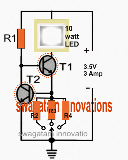
Referring to the above diagram, the design is a basic current controlled stage where T2 determines the maximum current limit of T1 by controlling the base potential of T1.
Circuit Operation
When the circuit is switched ON, T1 is triggered via R1 illuminating the LED. The process allows the entire current consumed by the LED to pass through one of the selected resistors (R2, R3, or R4) to ground.
This induces a proportionate amount of voltage across this current sensing resistor, which in turn forms the triggering voltage for the base of T2.
If this sensed voltage exceeds 0.7V, T2 is forced to trigger and ground the base potential of T1, thereby restricting its conduction, and subsequently restricting power to the LED.
The LED is now forced to shut down, however the process as the LED tries to shut off it also begins reducing the voltage across the particular base resistor of T2.
T2 now experiences a loss of triggering voltage and switches OFF, restoring the LED back to its original state via T1, until again the restriction process is initiated and this continues, maintaining a current controlled illumination over the connected LED, which is a Cree XM-L 10 watt lamp in this case.
Here R4 must be selected to allow the LED to illuminate with optimal consumption (max brightness), that is at its rated 3 amp level....R2 and R3 may be selected to offer any other desired lower current operation (lower intensity) to the LED such that by selecting these produces three different intensity levels for the LED.
Parts List
T1 = TIP 41 (on heatsink)
T2 = TIP 31 (on heatsink)
R1 may be calculated by using the following formula:
R1 = (Us - LEDv) x hFe / LED current
= (3.5 - 3.3) x 25 / 3 = 1.66 ohms
Wattage of the resistor = (3.5 - 3.3) x 3 = 0.6 watts or 1 watt
R2, R3, R4 may be calculated as:
Low Intensity = R2 = 0.7/1 = 0.7 ohms, wattage = 0.7 x 1 = 0.7 watts or 1 watt
Medium Intensity R3 = 0.7/2 = 0.35 ohms, wattage = 0.7 x 2 = 1.4 watts
Optimal Intensity = R4 = 0.7/3 = 0.23 ohms, wa ttage = 0.7 x 3 = 2.1 watts
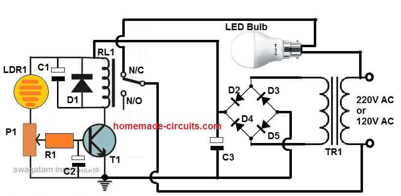
Operating through SMPS
In order to drive the proposed Cree LED from an mains operated SMPS, the following steps may be incorprated in order to implment the required volatge and current controlled operations:
1) Procure a 12V/3amp readymade SMPS.
2) Open it and look for the small optocoupler part on the PCB. This will look like a small 4-pin black IC.
3) Once you have located it, modify its input side by carefully conducting all the instructins as indicated in the following article: https://www.homemade-circuits.com/how-to-make-variable-current-smps/


Questions & Answers
thanks alot for sharing information now I can drive my leds 👍🏻🫡
Hi, do you have a reference and schematic for the High-Brightness Led Driver using the 66fb pwm ic
Hi, sorry, I don’t have it at this moment.
What is the max voltage I can put on a T6 led light before overloading and burning it up. I would like to makw it brighter with a little more voltage but I dont want to out to much on it and burn it up.
hi,i can found tip 35c,36c,42c,137 in stores..can i use them for t1 and t 2 ?
The transistor rating will depend on the current of the load or the LED, you can use TIP35 for T1, for T2 you can try 2N2222
Hi, can the same circuit be used to power a 20W led?
Which transistors did you use for this circuit? Thanks.
You can use TIP31 for T1, and 2N2222 for T2
Thanks for taking the time to reply.
Yes, by appropriately changing the resistor/transistor values
Hi Swagatam,
I want to use this circuit with Li ion battery with current consumption 500ma. Do I have to use the same transistor or any other
Thanks
Ganesh T.
Hi Ganesh, yes you can use the same exact circuit for your specific application, other transistors can be tried having identical specs. Make sure to calculate the parameters as per your requirements.
Sir, what will be happen if battery drop (ex to 2v5)?
Thx for dis site inspiring me lot !!
thanks jappar, at 2.5V the LED brightness will become too low.
What will be the needed resistor if I have a 10w 900mA LED?
please calculate it using the shown forula
Attiny85 has issues in it,as i have connected ir sender receiver in place of push button to dim up and down LED light output.
Internal oscillator set to 8Mhz this is i know only.But if we use 1 Mhz and 16Mhz problems remains the same.
With external oscillator i have not tried yet.
any frequency above 20kHz will never create any audible noise, so if it's in MHz then the question of noise cannot arise…I am not sure how the noise is created in your circuit, it's surely some other hidden issue.
How to increase frequency of arduino?.I have programmed attiny85 with arduino but it creates lot of noise how to handle it.
it can be done by modifying the program.
How did you set the frequency??
I am using 7805 and i have connected 100uf/25v to its output.
Also i have connected LED +ve to supply +ve and -ve to transistor collector.
connect a 100uF capacitor across transistor emitter/collector
or you can increase frequency to 20kHz
Hello;
I have develop circuit to dim this LED using arduino two push button type with tip122 transistor but the issue is that there is noise coming from arduino uno when the light dim or goes to full how to get rid of this noise any idea?
try connecting a 1uF/25V capacitor across the collector/emitter leads of the transistor and see if that helps….and a large capacitor (100uF/25V) across the supply pins of the Arduino.
Ok i will check. But it would nt make variable o/p, a fixed o/p only
yes, that's true, this is only to understand whether or not the current drop is due to the base resistor
Hi, i have been navigating your blog for some weeks now but most of what i see on your blog seems to be wild to me because i know nothing about electrical/electronics. Please any suggestion or ebooks on how to get started on electrical/electronics?
Hi, there are plenty of tutorial sites which will teach you electronics right from the basics to the most complex, so you can look for those sites, I am not sure about free ebooks
i have used 750 ma trafo. but i have tested with 12 v 1.5 amp adapter, same results.
remove the 5k pot and use only a single 470 ohm resistor from collector to base..and add a zener diode across the base and ground….the zener value should be slightly above the required output voltage.
Im to build a variable power suply. I used transformer, bridge, capacitor. Tip122 and 5k pot to feed variable dc to the base through a 470ohm. O/P is 0 to 12 v, but current is nt coming out. When i set the volt at 3.5 and conect an white led, its brightnes is far reduced, after 5 to 6v its light is quite normal. Why so?? Need help
what is the input current from your transformer? it must be at least 1 amp or more….