In this post I have explained how to build a simple plasma globe or a plasma ball circuit using very oridinary parts such as an automotive ignition coil, a triac, diac, and a few other passive elements.
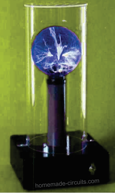
A plasma ball is a decorative display device in which a very high voltage in the order of many kilovolts is passed inside a glass ball, which results in the generation of a fascinating high voltage ionized plasma light display inside the glass ball

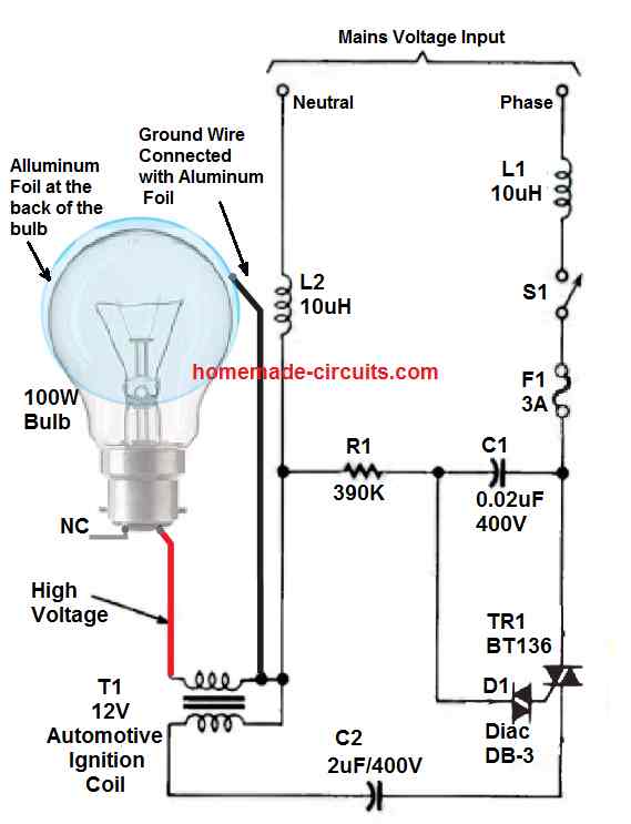
In our plasma ball circuit, an ordinary 100 watt bulb is used for the display unit. The glass lamp used in this design is customized by gluing a small sheet of aluminum foil directly to the back half of the glass, to make a kind of high voltage capacitor.
The filament inside the lamp bulb works like one particular plate of the capacitor, the glass of the bulb acts like the dielectric, and the aluminum foil serves like the second plate.
The aluminum foil, which acts like the negative plate of a polarized electrolytic capacitor, needs to be grounded by connecting the aluminum foil with the negative line. A high voltage is discharged inside the bulb by means of its inner filament electrode, ionizing the thin gas that stays within the glass envelope, producing a spectacular visual effect identical to an electrical lightening and storm.
Circuit Description.
The plasma ball or plasma Bulb circuit makes use of a triac diac combination, in which the diac acts like a trigger element and controls the current to the triac.
The main part of the circuit is an automotive ignition coil, T1, wired to supply a high-voltage charge of considerable power to ionize the gases present inside the glass of any ordinary incandescent lamp.
The entire circuit is powered directly the mains AC input.
The mains AC is supplied to the triac/diac stage via a phase-shift circuitry (which includes capacitor C1 and resistor R1) so that the triac is able to fire through the diac.
The moment TR1 fires or conducts, a small burst of electricity is driven through C2 to the primary side winding of T1. (Remember that as soon as AC mains input is first applied to the capacitor C2, it behaves like a short, after which the capacitor starts to charge towards the applied voltage level.)
This burst of electricity induces a strong rush of magnetic field inside the T1 primary winding, triggering an equivalent amount of stepped-up high voltage across its secondary winding of the ignition coil.
Next, as soon as the capacitor C2 starts to charge to its maximum peak level, the AC voltage to the diac begins to drop quickly. As the voltage drops downwards, the current necessary to keep triac switched ON sinks below the holding level, the triac now gets switched off.
After this positive cycle, the next half of the AC signal which is negative commences.
As the AC voltage cycle starts getting more negative, a potential begins appearing to the triac's trigger input via the diac, triggering it to fire. Since triacs are designed to conduct for both the AC half cycles, the triac fires during both the voltage cycles of the AC.
Now as TR1 conducts in the reverse direction, the C2 charge begins draining off, via TR1, which causes the next burst of electricity with opposite voltage to get induced in the primary winding of T1, causing the equivalent amount of stepped up voltage to be transferred in its secondary winding.
During these conductions of the triac, high-voltage output of more than 2 kv is generated at the secondary of T1 which is applied to the lamp, filament, creating a plasma ball display to be generated inside the lamp.
The C2 value should be selected such that it is not beyond 2-2.5 µF to protect against damage to the ignition coil T1.
Alternatively, if the C2 value is selected very small, the plasma ball sparking inside the bulb might fail to glow with satisfactory effect and brightness.
Inductors LI and L2 have been included in order to block the ignition coil switching transients and spikes from returning back to the home AC wiring or the AC line.
Plasma Ball Cabinet
The enclosure for the above explained plasma ball circuit can be fabricated in the following manner, using wooden box, or plastic box and tubes.
Do not use metal box or tube for the cabinet, since the whole set involves high voltages and mains AC input which can lead to electricity shocks or other electricity related accidents.
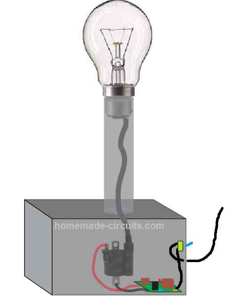
The aluminum foil behind the glass bulb is not shown in the above image, so make sure to stick an aluminum foil behind the bulb glass externally and connect it wire it with the circuit appropriately as per the indicated diagram layout.
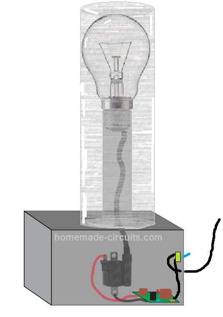
Once the above set up is built and tested, do not forget to cover the lamp structure with another plastic tube, so that the glass can e protected from accidental knocks and damages, as shown below:
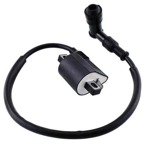
Ignition Coil
The ignition coil can be any automotive ignition coil, preferably the one that are used in motorcycles. The following image shows an example motorbike ignition coil which could be used for the above explained plasma ball circuit:
Another simple plasma ball circuit can be seen in the following article:
https://www.homemade-circuits.com/wp-content/uploads/2021/05/plasma-ball-circuit.pdf
WARNING: THIS PROJECT INVOLVES EXTREMELY HIGH LETHAL VOLTAGES. USERS ARE ADVISED TO MAINTAIN EXTREME CAUTION AND TAKE APPROPRIATE PROTECTION MEASURES WHILE BUILDING AND TESTING THIS CIRCUIT.


Questions & Answers
Good morning – was considering adding an amperage gage to the project. For aesthetics mostly, but if it worked – even better. The design is around household current so I suspect I would need AC amperage gages – would I place them off the ignition coil or elsewhere?
Thanks!!
Good morning, yes that may be possible. You will have to connect it in series with the phase line, or in series with the S1 switch.
You folks have been immensely helpful and patient – thank-you.
Another question: in the design I described earlier, will the plasma ball be “touchable”? I realize the high voltage wires coming off the coil need to be avoided but the insulating properties of glass – I suspect the answer is “yes”?
Thanks
Thank you, yes you guessed it right. The bulb glass can be touched due to the high insulating property of the glass, but just be careful from the coil HT wire.
Does the wattage rating of a bulb matter when using as a plasma light? Can you purchase a plasma bulb (only) with different gases or combination of gases?
Thanks for your quick reply and recommendations. Given I am clearly a novice – I’ll take any advice I can get. Appreciate it!
t
No problem!
The wattage is not important, the glass diameter is important. Bigger diameters will produce longer sparks which will look more spectacular compared to smaller diameter bulbs.
Question: many articles talk about a fly back transformer. Is the ignition coil in my design ahove acting as the transformer since the outpost is 12v.
Thanks
Terry
Oh, my question about the bulb wattage was relative to the durability of the filament – does a higher wattage constitute a more robust filament?
Yes, the ignition coil acts like a high voltage transformer.
The bulb filament is not relevant to the application. I think the sparks would still fly even if the filament was broken, or fused.
Am thinking of building a plasma ball using a 12v auto coil, a light dimmer switch (125v), 1.5uf 250v max capacitor, and G40, 100w incandescent globe bulb. Will this combination work?? Not looking for audio.
It should work, however I would recommend the setup as shown in the above circuit diagram.
Another question if I may – I note in the diagram the capacitor is 2uf – I am anticipating using 1.5uf – I am still new to capacitors – I understand the premise – but still learning the integration into a circuit.
Any thoughts on the choice?
You can try a 1.5uF, however if you find the sparks not being generated efficiently or are weak, then you may have to revert to a 2uF capacitor or use a couple of 1uF/400V in parallel.
i have a oringinal 300mm plasma ball , i want a high frequency driven power supply with audio interface , not mains driven must be dc 12/24v.science project for school.
You want a high frequency 12V output which can be modulated with audio? Is it?
Hie Engineer.
I have wired this circuit but im having a challenge. The capacitors are heating too much when the ignition coil is connected, if i remove the ignition coil capacitors will stop heating. Help me what could be the problem and how can solve it.
Thanks
Best Regards
Hi Binus, try using a 2uF/630V capacitor, you can also build it using two 1uF/630V capacitors in parallel
So are you saying the capacitor voltage is low and here i can get a maximum of 450v capacitors only. Can i arrange those in series to get a higher voltage
The capacitor may be heating due to high voltage spikes from the ignition coils, which can be perhaps solved by using higher voltage variants. Yes you can add them in series for increasing the voltage, but that will also reduce the uF value by 50%
Hie Engineer.
I tried to wire another bulb circuit which has a mosfet and a 555 timer. But on the coil the circuit was showing 24v supply to the coil yet i have 12v coil and with no 24v supply so i supplied 12v for both the timer and ignition coil.
Can that be possible or i need to have 24v supply for the coil although the coil is a 12v. The reason why i shifted to that circuit is i can’t achieve capacitors rating for the old circuit.
Hi Binus, the sparks will be less powerful and weaker if you use 12V instead of 24V, according to me.
Hie Engineer.
I tried to wire another bulb circuit which has a mosfet and a 555 timer. But on the coil the circuit was showing 24v supply to the coil yet i have 12v coil and with no 24v supply so i supplied 12v for both the timer and ignition coil.
Can that be possible or i need to have 24v supply for the coil although the coil is a 12v.
Hi Binus, sorry I cannot figure out the mosfet/555 circuit that you are referring to, so it will be difficult for me to suggest??
https://www.homemade-circuits.com/wp-content/uploads/2021/05/plasma-ball-circuit.pdf
This is the link to the circuit
The primary of an ignition col is normally rated between 50 V and 200 V AC, so it depends on the ignition coil specs….if your ignition coil is rated at 24 V then 12V to 24V can be usedand the output will be good, otherwise the output spark will be very weak.
Let me attach a link to that circuit
Hie Swag
I can’t find the electrolytic capacitors on this circuit. 0.02uf 400v and 2uf 400v.
Besides connecting capacitors in series and parallel to achieve this what else can i do to replace these capacitors.
And inductors also i can’t find them easily. Is there any way to replace them
Thanks
Hi Binus, For the capacitors you can use series parallel adjustment, but the value must be approximately the same as shown in the diagram.
Inductors are for suppressing Rf noise, they are not compulsory or crucial, you can remove them if you want
Okay thanks Engineer.
Best Regards.
Hie Eng Swag.
Want to build this light and would like to ask if the ignition coil has the specific specs or i can just use any.
Also am asking is it possible to have 2 bulbs in same circuit with one ignition coil, if possible i would be grateful if you guide me how to do it.
Thanks
Hi Binus, please note that this circuit was taken from an old magazine, and the prototype images were uploaded in the magazine so it means the design is a tested design.
for the ignition coil you can easily use any automobile ignition coil, preferably from a 2 wheeler, such as a scooter or a motorcycle.
Thanks Swag.
What about the part i have asked on connecting 2 bulbs in one circuit. Is that possible .
Also adding up to make the circuit look more unique how can i change the colour or adding colours to rotate
Hi Binus, yes you can use two bulbs according to me, but first test with a single bulb, then you can go for the second one in parallel
Okay thanks Swag , will give you feedback soon
No problem!
Sorry I do not have much time to give you feedback, though I watch your designs.
Thanks
Thank you once again Mr Swag for your continued support.
Your designs are very interesting and somehow understandable to electronics laymans . I really appreciate.
Could you possibly tell me the applications of this plasma ball circuit.
Best Regards
How are you Swag
I tried building the circuit for plasma bulb but the charge wasn’t getting inside the bulb it was attracting the outside ground only.
Is there a specific bulb i should use between vacuum type and gas filled filament bulbs.
Hi Binus, did you attach the aluminum foil at the back of the glass of the bulb. Remember only the foil must be connected to the ground line, and no other portion of the bulb must be connected to the ground.
The spark will have the tendency to jump only towards the ground wire linked areas, it cannot jump anywhere else.
No special type of bulb is required according to the original article, the bulb can be any large incandescent bulb, preferably a 200 watt bulb
Okay thanks Engineer.
let me try again and i will bring the feedback as usual.
Thank you Binus, the only application is for amusement and decoration purpose according to me…
More can be learned from the following post
https://en.wikipedia.org/wiki/Plasma_globe