In this post I have explained how to make an LM35 application circuit by understanding its datasheet, pinouts and other technical specifications.
By: SS kopparthy
LM35 Main Specifications
The IC LM35 is a temperature measuring device that looks like a transistor (most popular package is TO-92 package).
This device is found in most of the circuits that need to measure temperature as this device is a low-cost, reliable and with an accuracy as high as +-3/4 degrees Celsius.
The low cost of the sensor is because of its wafer-level trimming and calibration.
This IC is much better than the thermistor due to the accuracy in temperature measurement.
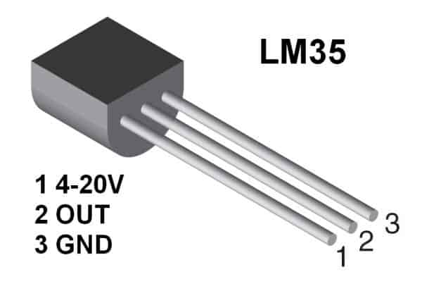
Pinout Details
As you can see in the above figure, the LM35 IC consists of three pinouts:
- The left pin is the Vcc pinout which accepts a +4V to +20V input DC.
- The center pin is the OUT pin of the LM35, which generates the varying output voltage in response to the varying ambient temperature or the temperature around its case.
- The right side pin is the ground pin which must be connected to the ground line of the circuit.
The sensor can work anywhere from -55 to 150 degrees Celsius.
The output temperature is directly proportional to the temperature change in Celsius. Also the other variant LM35C is available and its temperature range is -40 to 110 degrees Celsius.
Technical Specifications and Features
- Internally calibrated to generate readings directly in Celsius (Centigrade)
- Features a linear + 10-mV/°C scale factor
- Ensures high detection accuracy of 0.5°C (at 25°C)
- Capable of operating within the full temperature range between -55°C to 150°C
- Operates within the range of +4 V to +30 V
- Demonstrates a minimal current drain of less than 60 μA
- Exhibits low self-heating, measuring 0.08°C in still air
- Shows non-linearity of only ±¼°C on average
- Provides a low-impedance output, measuring 0.1 Ω for a 1-mA load
Details Explanation
This device gives out 10mV per degree Celsius rise in temperature.
This device consumes just 60µA current. So it does not drain much of power from the battery or power source.
Also, due to this low current, self heating of the device is as low as 0.1°C.
Other variants of this device that have different packages are also available such as TO-46 and TO-220.
These work same as the traditional one but differ in their usage areas and feasibility for a particular application.
For example, TO-46 metal package can be used to measure surface temperature as the metal package can be directly kept in contact with the surface whose temperature needs to be measured, while the TO-92 package could not as the device measures the temperature mostly based on the temperature of the terminals of the device as metal terminals conduct more temperature than the plastic casing.
Hence the TO-92 packaged LM35 is used to measure air temperatures in most of the circuits.
Block Diagram and Internal Functioning
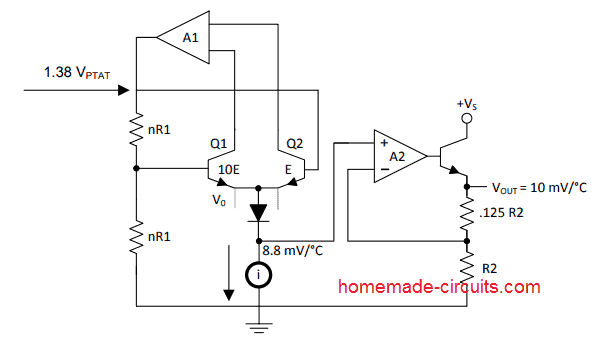
The above image shows the internal block diagram of the IC LM35. Here we can see that the IC is internally configured around a couple of opamps A1 and A2.
The first op-amp A1 is configured as an accurate temperature sensor through a feedback loop formed by a couple of BJTs configured as a current mirror.
The current mirror ensures a perfectly linear and a stabilized rate of temperature detection and prevents false triggering or inaccurate temperature readings at the output.
The sensed temperature is produced at the emitter side of the current mirror at a rate of 8.8mV per degree Celsius.
The output is applied to a buffer stage using another opamp A2 which is configured as a high impedance voltage follower.
This A2 stage acts as a buffer to reinforce the temperature to voltage conversion, and presents it at the final output pin of the IC via another high impedance BJT stage configured as an emitter follower.
The final output thus becomes highly isolated from the actual temperature sensor stage and delivers highly accurate temperature sensing response, which can be used by the user with an external switching stage such as a relay driver stage or a triac.
Using a Heatsink
The LM35 sensor IC can also be soldered to a heatsink fin to increase the accuracy and to decrease the sensing and response time in slowly moving air.
To understand much better, let’s take a look at the following circuit that uses LM35 to give an indication when the temperature is above the specified level:
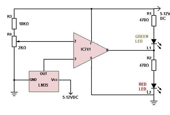
Temperature Detector Circuit Using LM35 IC
The LM35 circuit uses an op-amp IC741 as comparator. The op-amp is configured as an non-inverting amplifier.
That means when the LM35 detects high temperature, the output of the op-amp becomes +ve and the red LED lights up and the temperature falls below the specified level, the output of op-amp becomes –ve and the green LED lights up.
The high temperature level can be set with the help of preset in the circuit.
To set the temperature level for which the red LED lights up, you need to know the actual temperature where the circuit is being tested. For that you can use a multimeter.
As we know that the LM35’s output voltage increases 10mV per degree Celsius rise in temperature, we can use the multimeter to measure the output voltage and for example the voltage is 322mV, then the temperature at the place is 32.2°C.
You can even test the IC if it’s working or not using the above procedure. You can measure the actual temperature using an atmospheric thermometer and compare it with the values obtained with the LM35. You might not get the exact values but you should get close values.
LM35 Relay Control Circuit
An accurate LM35 based temperature controller can be built for controlling an external load such as a heater or a fan by attaching a relay driver stage to our previous as shown below:
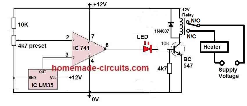
After understanding how the above LM35 circuit works, you should have understood how LM35 works practically in circuits.
Parts List
- Resistors
- 10K 1/4 watt CFR = 2nos
- 4.7K 1/4 watt CFR = 1no
- Trimpot 4.7K = 1no
- Diode 1N4007 = 1no
- Transistor BC547 = 1no
- IC 741 = 1no
- IC LM35 = 1no
- LED 5mm RED = 1no
- Relay 12V 400 Ohm = 1no



Questions & Answers
Hi
I’ve assembled the lm35 relay circuit except with an LM358 and a 2n3906 transistor controlling the relay. I’m using the circuit to turn a 60w light bulb on and off to keep my home brew at the right temperature. Everything works well except the relay chatters turning on and off. I’m thinking the 23 litres of home brew sits at the transition temperature for quite a while before changing enough to flick the relay one way or the other. I think I need to add hysteresis as described in a comment above. But how do I work out the resistor size between pin one and pin 3. The ideal home brew temp is around 20c I guess turn the light on 19c turn it off 20c. I found an online hysteresis calculator but it gave me results with many decimal points probably because the difference is .1v which isn’t much.
Hi, yes that’s happening because the BJT response is not sharp like an opamp, rather an analog response.
You won’t need an hysteresis to stop the relay chattering.
You can simply solve it by attaching a 100uF capacitor between base and ground of the BJT, that’s all, and additionally you can also connect another 100uF across the relay coil, to make the response even smoother….
Thanks for your help.
boa noite , tudo bem?. tenho uma duvida, ate quanto cm eu posso usar de cabo para ligar o LM35 placa. pois tenho a ideia de construir um projeto para arrefecimento do meu amplificador de potencia de som. pois pretendo fixar o LM35 no mesmo dissipador de calor onde está fixado os transistores.
Yes, the LM35 can be connected with short shielded wires, preferably below 1 meter for best stability. A few tens of centimeters normally will cause no issue. Mounting it on the same heatsink as the power transistors is the correct way but make sure it has good thermal contact and electrical insulation if required…..
Hi sir
I want to do a wax melting subsystem. I want to regulate the ambient temperature inside of a dispensing canister.
Now this requires two temperature inputs. The first input is to be implemented using the lm35 sensor and the second is to implemented as a variable dc used to emulate the ambient temperatures. The average of the two inputs should control a heating element. Can you help me with this.
Hi Mandla,
Sorry, the working concept of your application looks difficult to me, so I might not be able to provide a proper help for this project!
Hi sir,
1) If I put 10k at R4 what can change in to the circuit working?
2) Is it possible to include a second variable Resistance like the R4 in order to have the high and low limites of temperature?
Thank you for your help.
Joseph
Hi Joseph,
Yes you can replace R4 with a 10K preset
You can add an additional preset to set the low level restoration point, using the following modification:
A big thank for your help Sir.
Joseph
It’s my pleasure Joseph.
How can I understand the inscription in the TO92 packge, for instance: 52AB or 850RC if i have same reference LM35DZ by National? Thanks.
Can an lm35 be used as a transistor or is it only for temperature measurement?
it can be used only as a temperature sensor.
thank you for the reply.
Is it complicated to design lm35 sensor circuit n if we design, how much efficiency we could get n whether any changes in output compared to lm35 sensor
It is very simple to build a temperature sensor with LM35, and the efficiency can be expected to be optimum and as per the expected results. The output tripping will be very accurate if the op amp is set correctly.
please i a student i want make a temperature control standing fan but i was thinking of using thermistor as a sensor but i come across this site while searching on google i need some advice of the the sensor choice my regard
You can try the last circuit from the above article. Adjust the preset until the relay just clicks ON at the desired warm atmospheric temperature. Now keep the unit near a fast moving fan and check whether the relay clicks OFF or not.
Thanks I did it with LM35 and everything is working also as stated LM35 output is exactly 10mv per centigrade and there is no heating at all and very sensitive
Glad you could solve it….hope you enjoy the circuit now!
Why lm35 is very easy damaged during testing at first I used 5 volt input and measured wit DMM at output was millivolt 10mv/c° was corrected, after I tested many times output voltage became many thousands millivolt and not correct.
Sorry, that shouldn’t happen. At 5V across pin#1 and #3 can never damage the IC no matter how many times you connect as long as the polarity is right. Sometimes the device is duplicate in quality and may cause such problems.
I make this circuit and working fine.but in few seconds the ic75 become too hot.what is the reason?i used 12 volt 1amp transformer supply .and converted it in to dc
That is strange, because the IC is rated to easily work with 12V….try using a 7812 IC for the whole circuit and check again.
The circuit doesn´t work.
find the mistake in your circuit, it will surely work…do it stagewise