In this post we study about a automatic fan speed regulator circuit for controlling the temperature of a heatsink and from preventing the temperature to reach dangerous levels. This approach is to ensure safeguarding of the connected devices wit the heatsink.
Written by: Preeti Das
With the help of this circuit the speed of a fan motor self adjusts depending on the temperature of a heatsink that is intended to be controlled.
How it Works
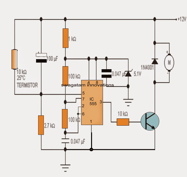
Here a standard thermistor device is used as the temperature sensor specified with a resistance value of 10 K at 25 degrees ambient temperature.
The motor to be controlled is powered by the PWM pulses from the IC 555 whose pulse rate cycle goes down from around 34% at room temperature (minimum speed) to 100% (maximum speed) when the temperature has reached a high.
These pulses are generated by 555 which is rigged to work as an integrated voltage controlled oscillator circuit. On the control voltage pin 5 a varying voltage is applied determined by the resistance of the thermistor which in turn depends on the temperature generated over the heat sink.
In order to ensure an immediate transfer of temperature, the thermistor must be attached or glued to the heatsink appropriately.
The shown 100uF capacitor connected in parallel with the thermistor shorts the supply with pin5 of the IC simulating a high temperature state for a few seconds during power switch ON so that the motor gets an initialization torque and is prevented from getting stalled.
The voltage to the IC 555 is regulated by the zener diode of 9,1V so that it allows the IC to work regardless of the input supply fluctuations.
To adjust the temperature triggering threshold at which the motor may be expected to speed up, you can change the value 2.7K resistor connected to pin 5 of 555 or even use a potentiometer for setting up the same.
Circuit Diagram
Note: The Transistor can be TIP122 for small motors rated at around 1 amp current.
2) Using LM358
Most electronic circuits with heat-generating power semiconductors equip at least one heatsink to dissipate the large amount of energy consumed. The rating of a heatsink depends on the maximum permissible temperature the silicon chip can withstand.
In this automatic heatsink temperature controller project, the heatsink monitor continuously observes the temperature of the heatsink.
In the range of 50°C to 60°, C the green LED will be lit, and the yellow one will light up when the temperature in the 70° - 80°C range.
Finally, when the temperature crosses the 80°C mark, the red LED will turn on. There is also an option to disconnect the load using a relay.
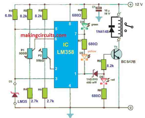
Naturally, the circuit is a window comparator. Sensor D1 delivered a control voltage escalates at a rate of 10 mV/°C.
When the sensor voltage drops below the voltage of wipers P1 and P2, the outputs of the opamps (A1 and A2) will become low and LED D2 will illuminate.
Output A1 will become high when the voltage across D1 goes above the wiper at P1 but still stays below of P2.
At the same time, D2 will be off and LED D3 will be lit. If the voltage crosses the wiper of P2, then both opamps’ output will be high.
Simultaneously, D5 will light up and the transistor T1 will be switched on. The function of Zener diode D4 is to make sure LED D5 is brightly lit as well as ensuring T1 conducts without inhibition.
How to Calibrate
Calibrating the unit is quite straightforward. You just need to place the sensor along with a calibrated thermometer in a plate of water. The next step is to heat it.
As the temperature rises, set P1 and P2 to a minimum and maximum resistances.
Also, set the cross over from green to yellow in the range of 50° - 60°C with P1. After that, set the limit from yellow to red in the range of 70° - 80°C with P2. Now that you have calibrated the sensor, you can attach it directly onto the heatsink.


Questions & Answers
Your web site is very impressive including it’s in depth easy to understand descriptions of a myriad of projects. Thanks for the very interesting reading. If possible could you design a circuit that would control the speed of a couple of 12 volt computer fans aimed at a wood burning stove that would start turning at around 90 degrees F and would increase to full speed in the neighborhood of 130 degrees F and with somewhat adjustable low and high limits.
Thanks very much and glad you liked the content of this site!
I think the first circuit is perfectly suitable for your application. Please test it and let me if it fulfills your specific requirement.
Is it possible to replace the TIP122 transistor with a MOSFET one, like IRFZ44NSTRLPBF? If yes, would this are there any other changes required? Thanks
Yes that’s possible, no changes will be required.
Peace be upon you.
How can I design a circuit that controls the speed of a fan according to the temperature change with a current of 70A and a voltage of 12.V DC?
I think you should try the first circuit shown in the above article, using a small motor.
If it works as per your requirement then we can upgrade the transistor with a MOSFET to handle 70 amps.
This is an amazing tutorial. Thank you so much. I’ve been looking for this for days now.
I wanted to ask whether this will work for a PWM DC Fan 12v 1A and allow me to control the speed starting at 50 °C and maxing out at 90 °C with a fairly smooth curve?
Cheers
Thanks for liking the post, appreciate your interest.
I could not correctly understand what exactly you want the above circuits to do. These circuits cannot produce a PWM output they can only cut off a circuit at a particular temperature or switch ON a fan at a specific temperature….
a little more elaboration might help!
I’m looking to control the speed of the DC fan dependent on temperature. The fan is PWM.
Basically I want it to start at a set temperature and then utilise varying voltage (or current) to increase the fan’s speed as the temperature rises.
I was hoping that this circuit would achieve this. Did I completely misread it?
Yes, you are right. This can be achieved using the first circuit which enables the motor speed to vary in response to changing temperatures….higher temperature causes the motor speed to increase and vice versa.
Strike that comment. I understand what you mean. By “first circuit” you meant the one based on IC 555. Is it possible to incorporate the leds technology from LM358 circuit to do the same in IC 555 one?
Yes that’s correct, I was referring to the first circuit from the top. Unfortunately LEDs cannot be used here for showing the cut-off levels., because the output is PWM and connecting LED will cause their illumination to gradually change depending on the pulse widths, but sharp ON/OFFs cannot be obtained.
i will try this project but transister( collecter) and +12 dc power suppy across outpot is 0.799 so fan is not working and transister (emitter) input is apply the negative voltage
which thermistor did you use? Connect LED in series with the transistor base, check whether it is illuminating or not under normal temperature.
In normal temperature pin#5 should be at 3V…please confirm these details.
bc547 transister is used and and i did not received the 3v in pin number 5
which thermistor did you use?
10D-9 thermistor
remove the thermistor the fan across output is 2.47v
did you use TIP122 for the transistor?
remove the thermistor and check the motor response, the transistor should be TIP122….BC547 will not work
which transister?
I asked about the thermistor, which thermistor did you use?
Good day sir. Please where and how is the thermistor connected to the second circuit diagram?
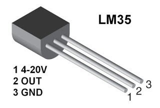
Hi Fredstev, there is no thermistor in the second concept, instead it uses an LM35 IC as the sensor.
I didnt understand your first answer, sir.
I do not know about the specs of 4D thermistor
Hello sir, i try to gather all the components for this circuit, but was unable to get thermistor 10k, i only find one written 47D, Can it serve same function?
2. Second question, can i use 5k or 10k preset in place of 2.2k?
sorry I am not sure about the value of the 47D you may ask your nearby component dealer for the details…
yes 5K perset will do instead of a 2.2K preset.
Meaning that i have to reverse the pin connection right? According to my understanding the motor’s negative will connec to collector and to ground while the emitter to the positive of power supply? Pls correct me if misunderstand u sir.
Also, should i maintain the base resistor as the 10k or i will change (increase or reduce) value. Pls help. Thanks.
yes that’s quite right, but motor’s negative must go to ground, and positive to collector of transistor.
With a TIP127 as the transistor, base 10k would be fine….
motor wires across collector and ground, positive supply to emitter
Thanks for your correction sir, am grateful and appreciate
you are welcome!!
Hello sir, can use TIP127 to drive the motor?
you can but for TIP127 you will have to connect the motor from collector to ground because it is a PNP
hi bro, i,ve made a circuit for pwm using ic 555 for controlling a dc motor( 4.5v). am able to vary the speed but problem is motor is not starting by itself. Initially motor is making a sound & when i rotate it by hand it starts. am using 1k resr & 10n cap for RC and 100k variable pot. ive even added two diodes in antiparallel. am using tip 31 to drive the motor.
so can u suggest any ideas for making it self starting?
and also can i replace transistor with a mosfet(irf 540) for driving.
Hi bro, it could be because the lowest PWM is too narrow to provide the required amount of current to the motor, you can try using a IRf540 mosfet or a TIP122 Darlington BJT and see if that improves situation. If not then you may have to add an extra resistor having 1/10th value of the pot value and add it in series with the pot terminal at the zero PWM side. This will restrict the PWM from becoming too much narrow and keep it at a level which may be just sufficient to initiate the motor movement at the lowest PWM
hi swagatam, can i swap the thermistor with an lm35 chip as that is what is easily obtainiable in my country
Ho Oladipo, yes you can try it by removing the thermistor and connecting the LM35 +/- pins with the supply and its out with pin#5, and see how it responds
Can we increase the speed of the fan only after the temperature of heatsink reaches 50°C..
you can probably do it by making the 2.7k resistor variable, and adjust it appropriately for achieving the results
you can use a 2N2222 or a 8050 or any similar rated transistor
Ok, thank you very much.
Hello. Please, tell us which zener is the correct, the 5.1V from the diagramm or the 9.1V from the text. Thank you, George.
use 5.1V zener, it's more appropriate.