A programmable sequential timer along with a triac dimmer is configured for making this kiln temperature controller circuit, further details are explained in the following article.
The idea was requested by Mr. Joe.
220V Kiln Controller with Timer
- I'm hoping you have some time to have a crack at a design I'm after.
- I've been trying to find a design for a kiln controller on the web to no avail.
- The main parameters would be a preheat cycle approx 1 hour, followed by a 3 step ramp up to an end point of 560c.
- Having temp displayed via an LCD and possibly a timer set through this would be great.
- My kiln element is currently 240v AC and drawing 17 amps.
The Design
The proposed kiln oven temperature controller circuit with timer can be built using the following explained cascaded sequential timers whose timings can be independently adjusted.
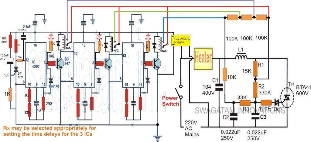
Referring to the above circuit design, the design is basically built around three identical IC 4060 timer stages and a standard light dimmer circuit enhanced with a high power triac for supporting the specified 17 amp kiln heater coil.
The entire kiln timer controller circuit can eb understood from the followng points:
The extreme left side IC 4060 timer circuit has all the component details which needs to be exactly replicated for the subsequent cascaded stages as these stages are identical with their componets and working specs. These stages are rigged to produce sequential timing outputs and activating the relevant relays in response to the set individual timings.
When the indicated power switch is pressed, the SCR at extreme left latches and grounds the pin#12 of the IC enabling it to initiate the counting process.
During this period its pin#3 is held at logic low ensuring that the attached BC547 and the relay stay switched OFF.
Also since the pin#12 of the second and the third IC are rendered at the positive supply level, these ICs stay disabled while the first IC is activated and counting.
As soon as the set time delay elapses, pin#3 of the left most IC goes high, activating the concerned relay and also latching the pin#3 high situation via the 1N4148 diode connected with pin#11.
The above activation causes the pin#12 of the second C to get grounded via the BC547 collector, which in turn enables the second IC 4060 now begins counting, and the process is repeated identically activating the second relay after the set elapsed delay.
The third IC and the relay follows the same pattern sequentially.
The relay contacts can be seen connected with 3 series 100k resistors which become the part of the triac dimmer circuit, and the total value of these resistors determine the conduction level of the triac which in turn decide the heat level of the attached heater coil.
Initially while the first IC 4060 is counting, all the three resistor become involved in series allowing the lower preheat process to begin.
When the first relay activates it shorts one of the 100K resistors causing higher conduction through the triac and higher current to flow through the heater, raising the temperature of the kiln proportionately to a higher level, this is repeated by the second relay also, elevating the kiln temperature a little more, ....until the final relay clicks causing the kiln temperature to soar to the required 560 degrees.
If you have any more queries regarding the discussed kiln temperature timer controller circuit, please feel free to jot them in through comments.
Calculating the Timing Components
The following formula can be used for assessing the various time periods for the individual ICs:
f(osc) = 1 / 2.3 x Rt x Ct
2.3 is a constant term which does not need any change.
In order to ensure an accurate output delays, the following condition must be maintained across the selected components:
Rt << R2 and R2 x C2 << Rt x Ct.


Questions & Answers
Why not using a basic controller to generate the sequential timing? A “bluepill” board (STM32F103) is less than 5$ and can be programmed easily.
I have made a couple of oven/kiln temperature controllers using the Arduino UNO for the temperature regulator, thermocouple and amplifier for temperature sensing and a triac switch as the final power control element. The design is really quite simple and they worked quite nicely. One way to make life difficult for yourself on temperature controllers is to attempt to use voltage control which is very non linear with respect to power and so causes problems with the regulator. A far better approach is to use pulse width modulation with a period of, say, 10 seconds (not the Arduino pwm).
If this is of any interest to you I could go into it further.
The circuit shown above uses a triac chopper concept, which is also a form of PWM applied to an AC. A triac chopper based heat control for a resistive load is probably the most efficient form of load control, in terms of cost as well as power saving.
As suggested by you a 10 sec variable pulse can be also used as effectively, no problems with that! But with a triac chopper the switching will be constant and smooth.