The circuit presented here is for a DC-CDI which are used in motorcycles. A DC-CDI is the one in which the high voltage (200-400VDC) is converted from 12V supply voltage.
Researched and Submitted by: Abu-Hafss
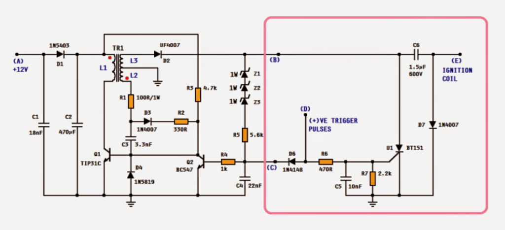
Studying the circuit, we see that it has two parts i.e. the smps CDI unit, enclosed in the pink box and the remaining circuit on the left is high voltage converter.
The working of the CDI may be found in this article.
The circuit on left is a high voltage converter based on a blocking oscillator. The components Q1, C3, D3, R1, R2, R3 and transformer T1 forms the blocking oscillator.
L1 is the primary coil and L2 is the feedback coil. C1, C2 and D1 are DC voltage smoothing components.
Audio/Video Representation
How it Works
When the circuit is powered on, R3 provides forward bais to the base of Q1. This turns on Q1 and current starts flowing thru the primary coil L1 of the transformer.
This induces voltage in the secondary or the feedback coil L2.
The red (phase) dots in the transformer symbol indicates that the phase of the voltage induced in L2 (and L3) is shifted 180°.
Which means when the bottom side of L1 is going negative, the bottom side of L2 will be going positive.
The positive voltage of the L2 is fed back to the base of Q1 thru R1, D1, R2 and C3. This causes the Q1 to conduct more hence, more current flows thru L1 and ultimately more voltage is induced into L2.
This causes L1 to saturate very rapidly which means no more changes in magnetic flux and hence no more voltage is induced into L2.
Now, C3 starts discharging through R3 and finally Q1 is switched off. This stops the current flow in L1 and hence the voltage across L1 comes to zero.
The transistor is now said to be "blocked". As C3 gradually loses its stored charge, the voltage on the base of Q1 begins reverting to a forward-bias condition by means of R3 thus switching on Q1, and hence the cycle is repeated.
This switching of Q1 is very fast such that the circuit oscillate at quite high frequency. The primary coil L1 and secondary L3 forms a step-up transformer and thus a fairly high alternating voltage (more than 500V) is induced in L3.
To convert it to DC a fast recovery diode D2 is deployed.
The zeners, R5 and C4 forms the regulator network. The sum of the values of the zeners should be equal to required high voltage to charge the CDI's main capacitor (C6).
Or alternatively a single TVS diode with desired breakdown voltage may be used.
When the output at the anode of D2 reaches the breakdown voltage (sum of zener values), the base of Q2 receives the forward bais and hence Q2 switches on.
This action steals the forward bais of Q1 thus stopping the oscillator temporarily.
When the output is dropped below the breakdown voltage, Q2 switches off and hence the oscillation resumes. This action is repeated very rapidly that the output is maintained slightly below the breakdown voltage.
The positive trigger pulse at point (D) in the CDI unit is also fed to the base of Q2. This is important to pause the oscillation because SCR U1 demands the current across its MT1/MT2 to be zero to be able to self-disconnecting.
Moreover, this increases power economy as all power supplied during discharging is wasted otherwise.
A special request from Mr. Rama Diaz to have multi CDI sections sharing a common HV converter circuit. Some parts of his request is quoted below:
Ok most engines these days don't have distributors anymore, they have a coil for each spark plug or in many cases have a dual post coil that fires 2 spark plugs at the same time, this is called "wasted spark" since only one of the two sparks is actually getting used each ignition event the other one just fires into the empty cylinder at the end of the exhaust stroke, so in this configuration a 2 channel CDi will run a 4cyl and 3 channel for 6cyl and 2 x 2 channel for v8 etc...
Almost all 4 stroke engines have 2 cylinders that are paired so only 1 coil (connected to 2 spark plugs) will fire at a time the other one/s will fire at the alternate ignition events driven by a separate trigger signal, Yes aftermarket ECU's have up to 8 completely separate ignition trigger signals....
yes we could just have 2 or 3 totally separate units but i would like to have everything contained in one unit if possible, and im thinking there would be some way to share some of the circuitry...
...so im thinking you could have one heavier current step-up section to provide the ~400v then have two (or 3) separate CDI coil driver sections with a separate trigger signal for each one to drive the coils independently....possible??
That way i could use 2 (or 3) dual post coils attached to 4 (or 6) spark plugs and have then all fire at the correct time in wasted spark configuration 🙂
This is exactly the way we often do it now inductively using simple transistor based ignitors but the spark strength is often not strong enough for turbo and high performance applications.
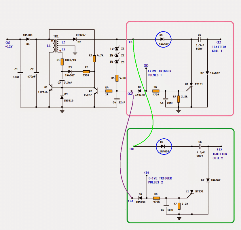
CIRCUIT DESIGN:
The entire circuit shown above can be used. The CDI unit enclosed in pink box can be used to drive one dual post ignition coil. For 4- cylinder engine, 2 CDI units; for 6-cyl, 3 CDI units can be used. When using multi CDI units, the diode D5 (encircled in blue) has to be introduced to isolate the C6 of each section.
TRANSFORMER SPECIFICATIONS:
Since the frequency of the oscillation is fairly (more than 150kHz), ferrite core transformers are used. A tiny 13mm EE core transformer can perfectly do the job but, handling such a small component might not be easy. A little bigger may be selected. Enameled copper wire 0.33 - 0.38mm for the primary (L1) and 0.20 - 0.25mm for the secondary L2 & L3.
The picture shows the bobbin's top view.
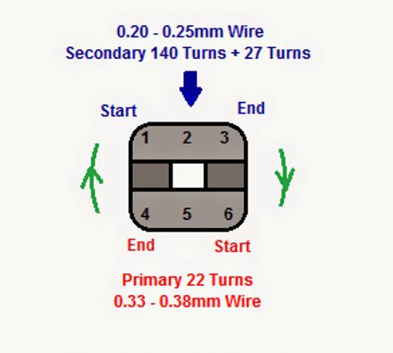
For primary winding, start from pin no. 6, wind 22 neat turns in the direction shown and end at pin no. 4.
Cover this winding with a transformer tape and then start the secondary winding. Starting from pin no. 1, wind 140 turns (in the same direction as that for primary) and make a tap at pin no. 2 and then continue another 27 turns and end at pin no. 3.
Cover the winding with tape and then assemble the 2 EEs. It is advisable to make an air gap between the 2 EEs. For this a tiny paper packing may be used. Finally use the tape to keep the 2 EEs united.



Questions & Answers
Swagatam,
What would be the maximum voltage output of this circuit with the given 140:22 transformer ratio?
Hi Pete,
It could reach 200V too 300V according to me…
Hi, can you advise typical current I would expect at both non trigger and at 2000rpm
Regards
Neville
New Zealand
At non-trigger (standby with the ignition on but engine not running), the circuit will draw a very low standby current, usually between 50 mA and 150 mA. This is because the circuit quickly charges the capacitor and then pauses.
At 2000 RPM, the current will increase noticeably to around 0.5 Amps to 1.5 Amps. At this speed, the circuit has to constantly and rapidly recharge the capacitor after every spark which pulls more steady power from your 12V battery.
Big thanks for the typical current draw. I plan on making circuit with my constructed arduino nano that is providing auto advance curve with trigger at 50degrees before TDC. I had play with simple circuit and had the issue of SCR latching on. Keen to try this circuit, I will develop pcb with nano and cdi, will share files and software when completed. This project will be for my 1951 Royal Enfield motorcycle.
Glad to hear the current draw details helped you! Your project for the 1951 Royal Enfield motorcycle using an Arduino Nano for the 50-degree auto advance curve sounds absolutely superb.
Regarding your previous issue where the SCR was latching on, this specific circuit diagram has a very special feature to fix exactly that. The trigger pulse coming to the SCR is also connected to the base of the transistor Q2. When the trigger pulse arrives, it instantly stops the high-voltage oscillator from running. This drops the charging current going into the SCR to zero for a millisecond, which breaks the latching loop and forces the SCR to successfully reset and turn off every single time.
So hopefully this layout will completely solve your latching problem when you build your new PCB. Please go ahead and design the board, and definitely share the Gerber PCB files and Nano software code here when you complete it so other builders can also benefit.
Seems like the air gap on the transformer is critical. Do you have a recommended thickness? Also should the air gap be on all 3 legs of the EE core? Once I acquire a few components I’ll give it a try.
Thanks Again
That’s right, air gap is critical, however it can be implemented simply inserting a piece of paper or a layer of insulation tape between the center limb of the E core, or between the two outer limbs of the E core….more info is given here:
https://www.homemade-circuits.com/how-to-create-air-gap-in-a-ferrite-core-transformer/
Thanks that’s the information that I needed. One more question, what frequency should Q1 be switching at? My current setup is switching at 3MHz, is that too fast?
Thanks, glad it helped, however i have no idea about the frequency, I guess it should be in kHz, maybe many 10s of kHz.
Yes, 3MHz looks too fast.
I’ll get a video once I finalize my testing and modifications. I’m seeing a drop in voltage at high RPMs and would like to try to push it higher. Mind you right now it is performing good since I am pushing 11,000 RPMs using wasted spark for a two stroke, that’s a spark every 2.5ms.
This is all bench testing and not on the engine yet.
Thanks again and hopefully I can get it to where I need it to be.
Perfect! thanks for updating the results, appreciate it a lot….let us know how it goes…
My circuit is working now, my problem was the polarity on the primary winding. Open circuit I’m able to get 550vdc and switch frequency is around 48KHz.
Thanks Again
That’s great, If possible please send me a 10 second video of its working, I will post it on youtube with your credentials on it…
Hi Mr Swagatam could you assist, i want to build my own CDI unit for a bombardier ds 650.
I need a circuit and the components to buy and built.Your assisstance is highly appreciated.
Regards,
gert.
Sure Gert, Do you have a pickup coil in your bike, if you do, then you can simply assemble the circuit as explained in the following article, and use it in your bike:
https://www.homemade-circuits.com/how-to-make-capacitive-discharge/
Hello Mr. Swagatman.
Let me introduce myself, I’m Eko from Indonesia. I’m interested in this and would like to try assembling and installing it on a 1984 Kawasaki KZ250R.
I think I’ll have difficulty determining the ignition timing. Is there a guide for this DC CDI? I mean, how to determine the ignition timing, including the length of the pickup pulser.
Thanks Eko,
The ignition timing is controlled by the pickup coil attached with the crank shaft of the engine…so you just need to configure the CDI trigger input with this pickup coil output for controlling the timing of the ignition firing…
Hello sir, I would like to have the schematic for a CDI unit for an engine with automatic advance or retard for a moped with a pulse coil. I’ve seen that they use a potentiometer to change the spark timing. I would like to have a diagram of it and the parts to assemble it. Greetings from Uruguay.
Hi Carlos, I will design it soon for you, however remember for this simple idea to work, you will have to first physically advance the pickup coil mechanically on the engine. You set the physical position of the sensor so that it triggers at the maximum possible advance the engine would ever need at highest RPM (for example, 30 degrees before top dead center), after this we can introduce an adjustable RC delay circuit which can be adjusted anywhere between this maximum advance or lowest minimum retard…
Hello, please recommend a DC CDI for a two-stroke engine.
Hi, you can try the circuits presented in the following article:
https://www.homemade-circuits.com/make-this-enhanced-capacitive-discharge/
Good evening Mr. Swagatam. I noticed in my CDI circuit that from around 5000 RPM onwards, the spark power decreases significantly. I assembled the circuit according to the description provided in this article. However, I am using a 1.5uF/400V polyester capacitor and the coil is from an inductive system. Could this be the problem?
Good evening Tony,
yes, both the capacitor value and the coil type could be the reason for the loss of spark energy above 5000 RPM. Try optimizing the capacitor with lower uF values and higher voltage variants, MKT type, and make sure the coil you are using is designed for CDI systems only and not for conventional inductive ignition systems
Good Mr. Swagatam, I made the circuit and it worked perfectly with lost double spark coil, then I remembered that I need a rpm limiter with two step for start.a simple analog circuit maybe with adjustment potentiometer. Does Mr have any suggestions?
That’s great news Tony! Glad you could make it work for you! For a RPM limiter, you can consider trying the following circuits, let me know if you have any further doubts:

https://www.homemade-circuits.com/frequency-to-voltage-converter-circuit/
Good day, sir. Swagatam and the rest. Returning only to inform the success of assembly and operation of the proposed circuit. I had some problems with the inverter but after solved it worked perfectly. I would like to send a video showing, but here it was not possible.
Thank you Tony, I am so glad the circuit worked for you.
Yes, it would be really great if you could sed me the video of the working unit.
Please send it to my email ID:
homemadecircuits
@gmail.com
Bom dia novamente Sr. Swagatam. Só mais uma pergunta apenas.
Qual a voltagem dos capacitores C1, C2, C3, C4 E C5 respectivamente que posso utilizar???
Hi Tony, all those capacitors can be rated at 50V minimum, or higher.
Boa noite Sr. Swagatam. Primeiramente gostaria de agradecer por disponibilizar o diagrama deste circuito (CDI DC) achei muito interessante e pretendo usa-lo em meu projeto. O projeto em questão é meu carro, um (VW Gol 1995 “Brasil”) com motor 4 cilindros turbo que eu mesmo montei o qual vou instalar uma injeção “SPEEDUINO”. Eu consigo usar este circuito para funcionar em conjunto com a injeção, coletando os sinais de ignição e utilizar sistema de centelha perdida ???
Ok Sr. Swagatam, vou estudar e construir o circuito. quando funcionar voltarei aqui para relatar sobre. Muito obrigado 👍
No problem, Tony! All the best to you!
Perfect, if you allow me, I have some more doubts.
The signal I want to use is the coil firing command coming from the Speeduino ignition output. This is a square wave 0–5V pulse, already with dwell time included (about 4 ms).
Can I feed this signal directly into point D of your circuit?
Also, does point E go to the + terminal of the ignition coil’s primary winding?
Then, where do I connect the – terminal of the coil? Because your circuit does not show a connection for that.
Yes, you can feed the square wave pulses to point D.
Point E should be connected to the primary coil of the ignition coil, which is probably + in a car ignition coil.
The ground of the CDI circuit will connect with the ground of your vehicle.
You can also consider try the following enhanced version of the circuit:
https://www.homemade-circuits.com/universal-multi-spark-enhanced-cdi/
Thank you Tony,
Yes you can use the above CDI circuit with battery and trigger it via Speeduino sync pulses.
To implement wasted spark, select a coil setup that supports it and ensure the CDI capacitor and SCR are strong enough.
Build carefully, checking voltage, timing and component ratings, especially for a car engine.
Hi Mr. Swagatam. Thank you for sharing this detailed guide! I followed your instructions and built the circuit exactly as described with the exception of couple of capacitors but very close to your spec. However, I noticed that the output from the UF4007 diode was only 38V DC. Is this the expected voltage, or could there be an issue with my setup or what do you think I missed? I’d appreciate any insights you might have. Thanks again for your valuable contribution!
i had the same problem in the zener diodes I had the error zener diodes how many volts you used should be about 300 v
there is only one problem that at high revs the voltage in c6 drops to 50 v, in short, the circuit does not work for demonstration purposes
Hey Sinan. I just wanted to take a moment to thank you for sharing your experience with the circuit. It really means a lot. Knowing that someone else has been through the same challenge makes the learning process feel a little less daunting! Yes, you are right! I looked at the specs of the Zener diodes I used and they were only 12V. Unfortunately I do not have any other Zener with higher ratings, but I take your word for it that it can’t maintain charge at higher RPMs.
I have an old Kawasaki mule that has a bad cdi and it has been discontinued. A second hand from ebay cost >$500. I may keep looking for other options. Thank you.
Hello Mr. Nestor, actually this circuit wase designed and tested by a different author, who is quite reliable as far as I know him. However since it is not designed by me, I am not sure about the results of this circuit, mostly because it involves an SMPS transformer. However, if your input DC is 12V then 38V is not bad if nothing is heating up. The output voltage from the smps transformer will depend on the switching frequency and also the turns ratio…
I appreciate your very prompt response. Thank you.