The post investigates a simple 2 pin oscillator circuit which may be inserted between the pickup coil and the CDI unit of a vehicle for achieving an induced multi trigger input in response to each signal from the pickup coil coil, this in turn is expected to enhance the sparking ability of the CDI coil. The idea was requested by Mr. Vimal.
Technical Specifications
Thank you for your help on the 555 buck boost circuit.Needed your help with one more circuit concept.Please note the details as below.1) In a petrol engine vehicle, the sparking is done due to an ignition coil. This coil is driven on 12 volts pure dc.2) In some experiments it was noticed that if the coil is supplied with pulsed dc at a certain frequency, the sparks become stronger due to the coil operating at its optimum resonant frequency without requiring an actual increase in operating input voltage or even bigger amperage draw.3) Increasing input voltage from 12 volts to higher voltages would also increase the spark intensity, but this would lead to damage of the primary coil in the long run. Also as the primary coil would heat up more due to higher voltage, it would draw more amps eventually leading to coil failure.4) I wanted your help in designing a circuit which is a passive dc to variable pulse dc converter, and does not require any ground connection to operate.The criteria of "NO GROUND CONNECTION" is due to the fact, that the circuit should fix in series on the +ve input line of the coil as it is not possible to modify the original harness of the vehicle to change coil connections.(+DC voltage IN and Pulsed DC voltage OUT fed directly only on the + live line connecting to the +ve terminal of the coil).5) The total amp draw of a regular ignition coil usually does not exceed 15 amps. Hence this circuit should be able to handle 15 amps of power draw passing through it.6) An increase of 1 - 2 volts above the input voltage is acceptable.7) I found a circuit online which does not require an external ground to operate. I do not understand the deep working of electronics, hence I am attaching it herewith for your reference. I am not sure if this design would work for the application that I have in mind.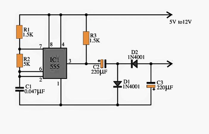
The Design
The attached circuit above might work if its 12V terminal is connected with the vehicle's +12V battery and the output from pin#3 to the pickup coil. This would enable breaking of the pickup signal into many short pulses, however the idea does not appear to be an efficient approach, since this would reduce the CDI triggering time to some lower level and in turn might cause a drop in the intensity of the generated sparks.
Any other more efficient configuration doesn't look feasible with the above the design.
The requested multi spark induction into an existing CDI ignition system may be achieved with the help of the following explained circuit:
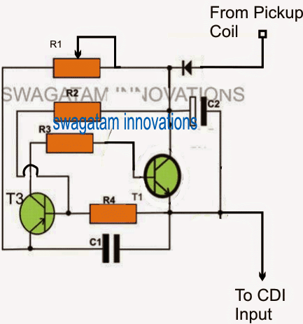
The circuit actually is inspired from a two pin automobile flasher circuit invented by me a long time ago.
The circuit actually oscillates in a regenerative kind of fashion, where the two transistors complement each other to turn ON fully and turn OFF fully at a set frequency.
You may also want to refer to the following related articles for more info:
Adjustabe CDI Spark Advance/Retard Circuit for Motorcycles
Universal Multi-spark Enhanced CDI Circuit for Automobiles
The frequency is determined by R1 and C1, any of these components can be altered for achieving the desired oscillations across the output terminals.
For the proposed multi spark variable frequency CDI ignition, the above circuit can be connected in series with the pick-up signal wire as illustrated in the diagram.
The voltage from each pulse is stored inside C2 for some extended limit of time, during which the circuit quickly delivers a number of short pulses, at a frequency determined by the C1, R1 combination.
R2, and R3 also influence the oscillation rates but these might also influence the pulse width of the output, and can be optimized some for getting the right amount of PWM, and a most effective response from the CDI coil.
Parts List
R1 = 100k preset
R2, R3 = 10K,
R4 = 33K,
T1 = TIP122
T3 = BC557,
C1 = 0.33uF/25V
C2 = 100uF/25V (other values can be tried)
D1 = 1n4007,


Questions & Answers
Hello, I would like to add this to a CDI I have built. It is triggered with points what exactly is the coil pickup? How could I integrated this into something that is triggered by breaking ground? Also I want to be sure that the first spark is immediate with this setup. IE I know it produces an oscillation but is the first spark on the relaxation phase of this circuit?
Hello, I understand your requirement, however presently I don’t seem to have the circuit with the specifications that you have mentioned.
Sorry forgot to mention. And of course the pulse that i generate later on to the cdi input will based on the rpm. That not a main issue here. The concern is how to make the square pulse works with the existing AC-CDI and coil. Thanks.
The pickup signal arrives when the piston is at an optimal distance near the spark plug…and this is the moment when the CDI needs to fire….
your MCU is the oscillator, the pick up signal is the timing signal at which the whole system needs to operate to produce the spark.
I see. But why use the trigger from pickup coil? Usually this feed to the scr in common cdi. Is this means that the triggers from pickup coil and tip122 acts as oscillator right?. Thus, the one that control the timing of spark is the signal/pulse fed to the scr.
the first design can be ignored, the last design is the one which must be considered.
you can eliminate the 555 stage entirely, and use the MCU output with the SCR gate.
the step up transformer along with the shown TIP122, a 12V battery and the MCU pulse will be required for the spark generation…not to forget the triggers from the pick up coil.
I see. From that post, i don't quite understand that the 1st design is not included the pickup pulse but the final design have included the pickup pulse. The square pulse is produced by 555 timer if im not mistaken. For me, im not sure how to produce sufficient current from square pulse that i produced from the microcontroller. Is the use of step up transformer is sufficient to do that?
yes that's possible…but the pick up pulse needs to have sufficient current in it for the procedures, here's an example circuit which you can refer to for getting a clear idea of the concept:
https://www.homemade-circuits.com/2013/01/make-this-enhanced-capacitive-discharge.html
Do u mean i need to step-up the square pulse at least up to 100V and then i can just feed it to the CDI. Which means, i just replace the pick-up pulse with the step-up square pulse right?? The coil already connected to the cdi in the existing hardness. So i dont need to change anything at the cdi output right?
A CDI unit and coil will work with AC as well as with a pulsating DC, so you can easily use a square wave pulse to obtain the intended results,,,,however the pulses will need to be stepped-up to at least 100V before feeding these two units.
Hi author, how can we change the timing of the existing AC-CDI to produce spark. Can one just replace the input pulse signal(from pick-up) to the cdi with square wave pulse from microcontroller? I want to avoid replacing the existing AC-CDI and ignition coil. Can u help me on which circuit i need to built so that i can use square pulse to replace pick-up pulse to the input of the cdi.
Hello! How can I calculate the time length of the resulting pulse train (and the pwm frequency)? I would like to try this on a single cylinder motorcycle (top ~11000 RPM or so). Thank you and best regards. Nice site 🙂
Hello, the length of the pulse train will depend on the pulse width from the pickup coil, which in turn will depend on the engine speed, which means faster engine speeds will produce shorter, quicker pulses, and vice versa