The circuit presented here is for a DC-CDI which are used in motorcycles. A DC-CDI is the one in which the high voltage (200-400VDC) is converted from 12V supply voltage.
Researched and Submitted by: Abu-Hafss
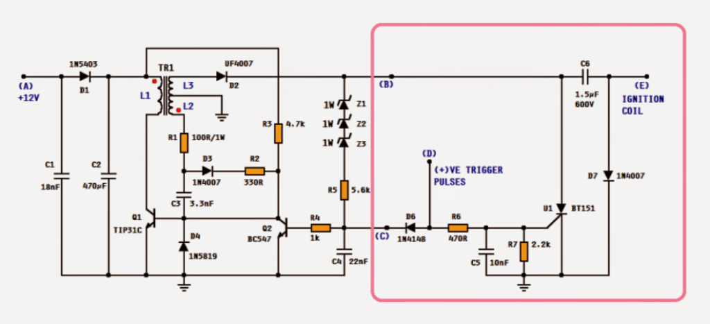
Studying the circuit, we see that it has two parts i.e. the smps CDI unit, enclosed in the pink box and the remaining circuit on the left is high voltage converter.
The working of the CDI may be found in this article.
The circuit on left is a high voltage converter based on a blocking oscillator. The components Q1, C3, D3, R1, R2, R3 and transformer T1 forms the blocking oscillator.
L1 is the primary coil and L2 is the feedback coil. C1, C2 and D1 are DC voltage smoothing components.
How it Works
When the circuit is powered on, R3 provides forward bais to the base of Q1. This turns on Q1 and current starts flowing thru the primary coil L1 of the transformer.
This induces voltage in the secondary or the feedback coil L2.
The red (phase) dots in the transformer symbol indicates that the phase of the voltage induced in L2 (and L3) is shifted 180°.
Which means when the bottom side of L1 is going negative, the bottom side of L2 will be going positive.
The positive voltage of the L2 is fed back to the base of Q1 thru R1, D1, R2 and C3. This causes the Q1 to conduct more hence, more current flows thru L1 and ultimately more voltage is induced into L2.
This causes L1 to saturate very rapidly which means no more changes in magnetic flux and hence no more voltage is induced into L2.
Now, C3 starts discharging through R3 and finally Q1 is switched off. This stops the current flow in L1 and hence the voltage across L1 comes to zero.
The transistor is now said to be "blocked". As C3 gradually loses its stored charge, the voltage on the base of Q1 begins reverting to a forward-bias condition by means of R3 thus switching on Q1, and hence the cycle is repeated.
This switching of Q1 is very fast such that the circuit oscillate at quite high frequency. The primary coil L1 and secondary L3 forms a step-up transformer and thus a fairly high alternating voltage (more than 500V) is induced in L3.
To convert it to DC a fast recovery diode D2 is deployed.
The zeners, R5 and C4 forms the regulator network. The sum of the values of the zeners should be equal to required high voltage to charge the CDI's main capacitor (C6).
Or alternatively a single TVS diode with desired breakdown voltage may be used.
When the output at the anode of D2 reaches the breakdown voltage (sum of zener values), the base of Q2 receives the forward bais and hence Q2 switches on.
This action steals the forward bais of Q1 thus stopping the oscillator temporarily.
When the output is dropped below the breakdown voltage, Q2 switches off and hence the oscillation resumes. This action is repeated very rapidly that the output is maintained slightly below the breakdown voltage.
The positive trigger pulse at point (D) in the CDI unit is also fed to the base of Q2. This is important to pause the oscillation because SCR U1 demands the current across its MT1/MT2 to be zero to be able to self-disconnecting.
Moreover, this increases power economy as all power supplied during discharging is wasted otherwise.
A special request from Mr. Rama Diaz to have multi CDI sections sharing a common HV converter circuit. Some parts of his request is quoted below:
Ok most engines these days don't have distributors anymore, they have a coil for each spark plug or in many cases have a dual post coil that fires 2 spark plugs at the same time, this is called "wasted spark" since only one of the two sparks is actually getting used each ignition event the other one just fires into the empty cylinder at the end of the exhaust stroke, so in this configuration a 2 channel CDi will run a 4cyl and 3 channel for 6cyl and 2 x 2 channel for v8 etc...
Almost all 4 stroke engines have 2 cylinders that are paired so only 1 coil (connected to 2 spark plugs) will fire at a time the other one/s will fire at the alternate ignition events driven by a separate trigger signal, Yes aftermarket ECU's have up to 8 completely separate ignition trigger signals....
yes we could just have 2 or 3 totally separate units but i would like to have everything contained in one unit if possible, and im thinking there would be some way to share some of the circuitry...
...so im thinking you could have one heavier current step-up section to provide the ~400v then have two (or 3) separate CDI coil driver sections with a separate trigger signal for each one to drive the coils independently....possible??
That way i could use 2 (or 3) dual post coils attached to 4 (or 6) spark plugs and have then all fire at the correct time in wasted spark configuration 🙂
This is exactly the way we often do it now inductively using simple transistor based ignitors but the spark strength is often not strong enough for turbo and high performance applications.
CIRCUIT DESIGN:
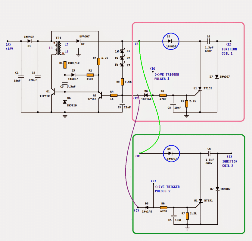
The entire circuit shown above can be used. The CDI unit enclosed in pink box can be used to drive one dual post ignition coil. For 4- cylinder engine, 2 CDI units; for 6-cyl, 3 CDI units can be used. When using multi CDI units, the diode D5 (encircled in blue) has to be introduced to isolate the C6 of each section.
TRANSFORMER SPECIFICATIONS:
Since the frequency of the oscillation is fairly (more than 150kHz), ferrite core transformers are used. A tiny 13mm EE core transformer can perfectly do the job but, handling such a small component might not be easy. A little bigger may be selected. Enameled copper wire 0.33 - 0.38mm for the primary (L1) and 0.20 - 0.25mm for the secondary L2 & L3.
The picture shows the bobbin's top view.
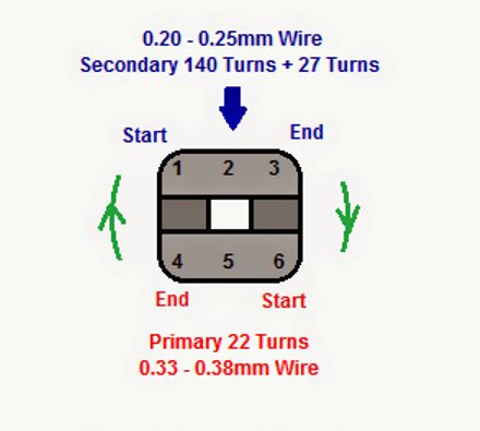
For primary winding, start from pin no. 6, wind 22 neat turns in the direction shown and end at pin no. 4.
Cover this winding with a transformer tape and then start the secondary winding. Starting from pin no. 1, wind 140 turns (in the same direction as that for primary) and make a tap at pin no. 2 and then continue another 27 turns and end at pin no. 3.
Cover the winding with tape and then assemble the 2 EEs. It is advisable to make an air gap between the 2 EEs. For this a tiny paper packing may be used. Finally use the tape to keep the 2 EEs united.


Questions & Answers
Swagatam,
What would be the maximum voltage output of this circuit with the given 140:22 transformer ratio?
Hi Pete,
It could reach 200V too 300V according to me…
Hi, can you advise typical current I would expect at both non trigger and at 2000rpm
Regards
Neville
New Zealand
At non-trigger (standby with the ignition on but engine not running), the circuit will draw a very low standby current, usually between 50 mA and 150 mA. This is because the circuit quickly charges the capacitor and then pauses.
At 2000 RPM, the current will increase noticeably to around 0.5 Amps to 1.5 Amps. At this speed, the circuit has to constantly and rapidly recharge the capacitor after every spark which pulls more steady power from your 12V battery.
Big thanks for the typical current draw. I plan on making circuit with my constructed arduino nano that is providing auto advance curve with trigger at 50degrees before TDC. I had play with simple circuit and had the issue of SCR latching on. Keen to try this circuit, I will develop pcb with nano and cdi, will share files and software when completed. This project will be for my 1951 Royal Enfield motorcycle.
Glad to hear the current draw details helped you! Your project for the 1951 Royal Enfield motorcycle using an Arduino Nano for the 50-degree auto advance curve sounds absolutely superb.
Regarding your previous issue where the SCR was latching on, this specific circuit diagram has a very special feature to fix exactly that. The trigger pulse coming to the SCR is also connected to the base of the transistor Q2. When the trigger pulse arrives, it instantly stops the high-voltage oscillator from running. This drops the charging current going into the SCR to zero for a millisecond, which breaks the latching loop and forces the SCR to successfully reset and turn off every single time.
So hopefully this layout will completely solve your latching problem when you build your new PCB. Please go ahead and design the board, and definitely share the Gerber PCB files and Nano software code here when you complete it so other builders can also benefit.
Seems like the air gap on the transformer is critical. Do you have a recommended thickness? Also should the air gap be on all 3 legs of the EE core? Once I acquire a few components I’ll give it a try.
Thanks Again
That’s right, air gap is critical, however it can be implemented simply inserting a piece of paper or a layer of insulation tape between the center limb of the E core, or between the two outer limbs of the E core….more info is given here:
https://www.homemade-circuits.com/how-to-create-air-gap-in-a-ferrite-core-transformer/
Thanks that’s the information that I needed. One more question, what frequency should Q1 be switching at? My current setup is switching at 3MHz, is that too fast?
Thanks, glad it helped, however i have no idea about the frequency, I guess it should be in kHz, maybe many 10s of kHz.
Yes, 3MHz looks too fast.
I’ll get a video once I finalize my testing and modifications. I’m seeing a drop in voltage at high RPMs and would like to try to push it higher. Mind you right now it is performing good since I am pushing 11,000 RPMs using wasted spark for a two stroke, that’s a spark every 2.5ms.
This is all bench testing and not on the engine yet.
Thanks again and hopefully I can get it to where I need it to be.
Perfect! thanks for updating the results, appreciate it a lot….let us know how it goes…
My circuit is working now, my problem was the polarity on the primary winding. Open circuit I’m able to get 550vdc and switch frequency is around 48KHz.
Thanks Again
That’s great, If possible please send me a 10 second video of its working, I will post it on youtube with your credentials on it…
Hi Mr Swagatam could you assist, i want to build my own CDI unit for a bombardier ds 650.
I need a circuit and the components to buy and built.Your assisstance is highly appreciated.
Regards,
gert.
Sure Gert, Do you have a pickup coil in your bike, if you do, then you can simply assemble the circuit as explained in the following article, and use it in your bike:
https://www.homemade-circuits.com/how-to-make-capacitive-discharge/
Hello Mr. Swagatman.
Let me introduce myself, I’m Eko from Indonesia. I’m interested in this and would like to try assembling and installing it on a 1984 Kawasaki KZ250R.
I think I’ll have difficulty determining the ignition timing. Is there a guide for this DC CDI? I mean, how to determine the ignition timing, including the length of the pickup pulser.
Thanks Eko,
The ignition timing is controlled by the pickup coil attached with the crank shaft of the engine…so you just need to configure the CDI trigger input with this pickup coil output for controlling the timing of the ignition firing…
Hello sir, I would like to have the schematic for a CDI unit for an engine with automatic advance or retard for a moped with a pulse coil. I’ve seen that they use a potentiometer to change the spark timing. I would like to have a diagram of it and the parts to assemble it. Greetings from Uruguay.
Hi Carlos, I will design it soon for you, however remember for this simple idea to work, you will have to first physically advance the pickup coil mechanically on the engine. You set the physical position of the sensor so that it triggers at the maximum possible advance the engine would ever need at highest RPM (for example, 30 degrees before top dead center), after this we can introduce an adjustable RC delay circuit which can be adjusted anywhere between this maximum advance or lowest minimum retard…
Hello, please recommend a DC CDI for a two-stroke engine.
Hi, you can try the circuits presented in the following article:
https://www.homemade-circuits.com/make-this-enhanced-capacitive-discharge/
Good evening Mr. Swagatam. I noticed in my CDI circuit that from around 5000 RPM onwards, the spark power decreases significantly. I assembled the circuit according to the description provided in this article. However, I am using a 1.5uF/400V polyester capacitor and the coil is from an inductive system. Could this be the problem?
Good evening Tony,
yes, both the capacitor value and the coil type could be the reason for the loss of spark energy above 5000 RPM. Try optimizing the capacitor with lower uF values and higher voltage variants, MKT type, and make sure the coil you are using is designed for CDI systems only and not for conventional inductive ignition systems
Good Mr. Swagatam, I made the circuit and it worked perfectly with lost double spark coil, then I remembered that I need a rpm limiter with two step for start.a simple analog circuit maybe with adjustment potentiometer. Does Mr have any suggestions?
That’s great news Tony! Glad you could make it work for you! For a RPM limiter, you can consider trying the following circuits, let me know if you have any further doubts:

https://www.homemade-circuits.com/frequency-to-voltage-converter-circuit/
Good day, sir. Swagatam and the rest. Returning only to inform the success of assembly and operation of the proposed circuit. I had some problems with the inverter but after solved it worked perfectly. I would like to send a video showing, but here it was not possible.
Thank you Tony, I am so glad the circuit worked for you.
Yes, it would be really great if you could sed me the video of the working unit.
Please send it to my email ID:
homemadecircuits
@gmail.com
Bom dia novamente Sr. Swagatam. Só mais uma pergunta apenas.
Qual a voltagem dos capacitores C1, C2, C3, C4 E C5 respectivamente que posso utilizar???
Hi Tony, all those capacitors can be rated at 50V minimum, or higher.
Boa noite Sr. Swagatam. Primeiramente gostaria de agradecer por disponibilizar o diagrama deste circuito (CDI DC) achei muito interessante e pretendo usa-lo em meu projeto. O projeto em questão é meu carro, um (VW Gol 1995 “Brasil”) com motor 4 cilindros turbo que eu mesmo montei o qual vou instalar uma injeção “SPEEDUINO”. Eu consigo usar este circuito para funcionar em conjunto com a injeção, coletando os sinais de ignição e utilizar sistema de centelha perdida ???
Ok Sr. Swagatam, vou estudar e construir o circuito. quando funcionar voltarei aqui para relatar sobre. Muito obrigado 👍
No problem, Tony! All the best to you!
Perfect, if you allow me, I have some more doubts.
The signal I want to use is the coil firing command coming from the Speeduino ignition output. This is a square wave 0–5V pulse, already with dwell time included (about 4 ms).
Can I feed this signal directly into point D of your circuit?
Also, does point E go to the + terminal of the ignition coil’s primary winding?
Then, where do I connect the – terminal of the coil? Because your circuit does not show a connection for that.
Yes, you can feed the square wave pulses to point D.
Point E should be connected to the primary coil of the ignition coil, which is probably + in a car ignition coil.
The ground of the CDI circuit will connect with the ground of your vehicle.
You can also consider try the following enhanced version of the circuit:
https://www.homemade-circuits.com/universal-multi-spark-enhanced-cdi/
Thank you Tony,
Yes you can use the above CDI circuit with battery and trigger it via Speeduino sync pulses.
To implement wasted spark, select a coil setup that supports it and ensure the CDI capacitor and SCR are strong enough.
Build carefully, checking voltage, timing and component ratings, especially for a car engine.
Hi Mr. Swagatam. Thank you for sharing this detailed guide! I followed your instructions and built the circuit exactly as described with the exception of couple of capacitors but very close to your spec. However, I noticed that the output from the UF4007 diode was only 38V DC. Is this the expected voltage, or could there be an issue with my setup or what do you think I missed? I’d appreciate any insights you might have. Thanks again for your valuable contribution!
i had the same problem in the zener diodes I had the error zener diodes how many volts you used should be about 300 v
there is only one problem that at high revs the voltage in c6 drops to 50 v, in short, the circuit does not work for demonstration purposes
Hey Sinan. I just wanted to take a moment to thank you for sharing your experience with the circuit. It really means a lot. Knowing that someone else has been through the same challenge makes the learning process feel a little less daunting! Yes, you are right! I looked at the specs of the Zener diodes I used and they were only 12V. Unfortunately I do not have any other Zener with higher ratings, but I take your word for it that it can’t maintain charge at higher RPMs.
I have an old Kawasaki mule that has a bad cdi and it has been discontinued. A second hand from ebay cost >$500. I may keep looking for other options. Thank you.
Hello Mr. Nestor, actually this circuit wase designed and tested by a different author, who is quite reliable as far as I know him. However since it is not designed by me, I am not sure about the results of this circuit, mostly because it involves an SMPS transformer. However, if your input DC is 12V then 38V is not bad if nothing is heating up. The output voltage from the smps transformer will depend on the switching frequency and also the turns ratio…
I appreciate your very prompt response. Thank you.
Hello Swagatam,
Thank you for sharing your expertise.
I am trying to inspect/repair an old DC CDI unit for a single cylinder, 4-cycle 250cc bike.
I am having a terrible time trying to remove the OEM’s protective gel, which is mixed with many small white stones (silica?).
Do you know what is the right solvent for quickly and effectively removing this junk? I was not able to find any useful info on the net.
Thanks.
Hello Dustin,
I guess you are referring to the hard epoxy which is put into the CDI box to hide its details by the manufacturer. Unfortunately, there’s no solvent or chemical available which can dissolve this epoxy. The only way is perhaps to slowly and carefully break it bit by bit, until the circuit board is sufficiently retrieved.
Hello, I have built the circuit according to the diagram.
However, instead of a 3.3nF capacitor, I used a 3.9nF capacitor, and instead of an 18nF capacitor, I used a 15nF capacitor.and for C2 I use 470uf 16 volt electrolytes capacitor, I also built the transformer according to the formula.For building the transformer, I used enameled wire from a miniature relay and an small armature…
But the circuit doesn’t work. I’ve checked it multiple times, and everything seems correct. However, when I connect the input voltage, the TIP31 transistor gets very hot. I replaced it with a TIP41 transistor, but it still gets hot, and the capacitor doesn’t charge…
Is it possible that some of the components are faulty?
What do you think could be the issue? Please guide me; I would appreciate your help.
Thank you, my friend. Best regards!
trafonun çıkışları şemaya uygun değil. dikkat etmemişler tasarım hatalı
ya trafoyu ters pinlerden saracaksınız yada şemayı ters çevireceksiniz
140 spir lik sargının çıkışı uf4007 diyotunun anot ucuna denk gelmesi lazım.
Hi, the above circuit was designed by a different author Mr. Abu Haffs, however it was tested by him to be OK.
Actually the transformer is the heart of the circuit and if the windings are not wrapped correctly or if the direction of the winding is not correct then the circuit will fail to oscillate and the transistor will start heating up.
You can try swapping the wire ends of either the primary winding or the secondary winding and check the response.
Hello, regarding capacitor C2, which type of capacitor should I use?
The capacitor is 470 microfarads, but I could only find electrolytic ones. However, the polarity is not specified in the circuit. What alternative value or type can I use instead?
Thank you for your response.
C2 capacitor can be an electrolytic, because it is fed from a rectifier diode, so electrolytic can be used.
The value can be anything above 220uF
Interesting project, I have to try it, I have almost all the components and I only need to make the transformer, the only component that I think I will not get on the market is the TVS since here in Guatemala it is difficult to locate these components and especially because the value of it.
I already designed the single-sided printed circuit board, it’s just for testing.
Greetings from Guatemala, Sergio Lorenzana.
Thank you Sergio, glad you found the project interesting.
Hope it works for you.
Let me know how it goes….
hello dear Swagatam thanks for sharing this project,
I want to make this but I’m having a little trouble
can you share PCB diagram and full part for me?
I appreciate it
Thank you David,
However, I am sorry, i do not have the PCB design for the above circuit. You may have to contact a professional PCB manufacturer for designing the PCB layout and for producing the sample PCBs.
Dear Swagatam, have a nice day!
I am making a friend a PCB according to your diagram for his 150cc motorcycle 1 cylinder.
For obvious reasons, the circuit is sensitive to the quality of the components.
Can I use the following parts?
BT151-800R as U1
BC547C as Q2
MJE13005 as Q1
SF18 as D2
SK56 3A rated SMD as D1
Please tell me whether it is possible to shift the ignition timing in this circuit using elements. To an earlier or later position. You may need to install a toggle switch
Regards
Q2-2n5551(bc546 does not work well in this circuit, the CE saturation voltage should be less than 0.6V, I used an optocoupler, it also works great)
Q1-KT805BM (any letter index) or any transistor from a computer power supply
BT151 any fit.
D1 I would put from 5A, not necessarily shots, any.
Thank you Sergey,
You can use the mentioned parts except MJE13005, which might not work well for a 12V application, instead you can use any other 50V or 100V 5 amp transistor.
I don’t think this circuit can be modified to shift and customize the ignition timing, I am not so sure about it.
Sir what are the first circuit capacitor voltage values.can you send parts list pls
PADMAHARSHA, The capacitor voltage values that are not specified in the diagram are all 50 V rated. Resistors are all 1/4Watt 1% MFR type.
Hi ,
Does motorcycle has a alternator as well. Please let me know.
Is thta not part of CDI circuit.
Thanks
Susanta’
Yes, all vehicles have an alternator. A voltage of around 100 to 200 V AC is fed to the CDI for generating the sparks
Hi
I made this circuit
The first problem for me was the number of turns of the transformer. When I reduced the number of primary turns to 10 and the number of feedback turns to 2 , the circuit was fixed.
Now it works properly but at low speed
When the rpm goes up to ~3000, the spark is very low
Can you tell me my problem?
(I changed the number of turns because the transistor was saturation)
Thank you
Hi,
I am glad you could make this circuit successfully.
At high speeds it seems the current entering the CDI coil cannot reach optimal value. I guess the C6 should be increased a bit, which might solve the problem, but I am not sure I am only guessing.
Try increasing the value of C6 from 1.5uF to 3 uF/600V and check the response
Hi Swagatam, Joop here from Holland. I made two dc cdi ignition and it Works 100% up to 350hz with a sparkdistance of 20mm with a quality Wilma mkp 1uf 630Volt condenser and a good coil. It draws 7-8 Watt at 14Volt With for 75 Volt zeners and a very small transformer.
Now my question: Can I use 18 or even 20Volt? I need 480hz. My bike is a triple cilinder, and it has one cdi with a strange distributor wich connects the ground off the 3 coils in turns to ground.
I tryed it for a short time and it gives a stronger spark up to 530hz.
Thank You for schering you knowledge.
Regards Joop
Hi Joop,
You can use 18 to 20V, but make sure to increase the gate resistor value of the SCR to around 470 ohms 1/2 watt. The frequency of the sparks will depend on the RPM of the bike wheel. The wheel rotation will be converted to pulses from the pickup coil and sent to the CDI for triggering the ignition coil. As your bike moves faster the sparks will become faster and vice versa.
I would like to try construct the circuit for a half-bridge for a DC to DC inverter . I have a hope that for a large part of my desired application, you did a commendable job as if you are an alien from space. I shall try to make a minor modification or none at all.Thankfor your effort in arranging that the converter must operate with the fire semiconductor there are other areas that deserves technical appreciation, also I leave that to other. Thank you Homemade.
Alfred,
Malawi.
Thank you Alfred, glad you found the post helpful! Surely, you can construct it for your inverter project. Hope it works for you.
All the best to you!
Hi Swagatam,
I made this circuit but i’m not satisfied with final results because i’m facing these issues
Can you please help me, how can i overcome these issues?
Hamza.
Hi Hamza, try increasing the primary turns to 30 or 40 turns and check if that reduces the current consumption or not?
The transformer is the crucial part in this design, if it is not built correctly or the winding polarity is not correct, there could be problems. Make sure to put an paper gap between the E-core edges.
Hi, i been looking gor a good dc cdi drawing and think i found on, yours.
But it is for 4cyl car with distributor. This mean 2 ingnitions/rew. Do this construction manage to reload so fast. It Will be 8000r/min order 16000 unloads/min.
Tanken in advance.
Eric.
Hi, the above CDI circuits are for two wheeler and 3 wheeler application, not for 4 wheeler and is not suitable for 8000 RPM speeds.
Would it be possible to modificate it for 4 cyl with 8000 rpm? What is the week part, transformer or the ingnition capasitor?
Or other?
regards,
Eric
Sorry, I have no idea what type of CDI is required for operating a 4 cycle engine, so not sure how the above circuit can be modified?
The capacitor, SCR and the transformer are the 3 important parts of the circuit.
I have a 12VDC Car battery Source only. I am trying to make a CDI for my single sparkplug engine. I cannot find a way to make 200-300VDC without a very expensive transformer. Is there a cheap and simple way? Could I just buy an inverter from amazon 12vdc to European 220vac then a diode bridge to make DC? Please advise.
You can try the first concept from the following article. The transformer is an ordinary 0-12V/220V step down transformer connected the opposite way round for stepping up the 12V from the 555 oscillator into 220V AC for the ignition coil..
https://www.homemade-circuits.com/make-this-enhanced-capacitive-discharge/
What would a spark advance and rev limiter look like?
How high can it rev?
Do you etch your own circuit boards, can you recommend someone?
I do not know much about spark advance and rev limit.
I don’t etch PCBs I build them on strip boards through manually soldering the connections
regarding this circuit i have checked the trigger pulse with a occilloscope and got a reading of .8 v . do you think it will be high enough to opperate your circuit trigger ?
0.8V may not be enough for triggering the above explained circuits. Because D6 will itself drop about 0.6, and the remaining 0.2V will not be enough to trigger ON the Q2….a minimum of 2 V could be required for triggering Q2 and the SCR effectively…
Sir
What are the 3 zener diode specs for dc cdi
Padmaharsha, The zener diodes decide the voltage level that can be stored in the capacitor C6, which in turn decides how strong the CDI output voltage and the spark will be.
Be careful if you build this circuit. Capacitor C6 will hold it charge 400V even after power
has been removed. If you touch the back of the circuit board the capacitor will discharge giving you a mighty shock. The circuit packs a mighty punch. Treat with respect.
When running correctly the circuit will pull about 200ma at 12V and give out 400V.
Thanks Swagatam for posting this circuit.
Thanks for your feedback Alan, I hope the users will find it useful!
Hello
What are the necessary changes for this circuit to operate on 6V? In the primary winding of the transformer I put 11 turns but unfortunately I can not get more than 29v per output.
Thanks
Hello, The coil winding determines the output voltage so you may keep experimenting with the number of turns until the right output voltage is achieved. The idea was contributed by another author therefore I can’t suggest much on this.
Hi
What needs to be changed to run this off 48 volts?
Thank You!
Hi, nothing needs to be changed, you can use the circuit as is…however, the signal from the pick up must be 12V, and the CDI coil must be rated at 48V
Wahat is ZD1,ZD2 AND ZD3…..
zener diodes
Hi Swagatam,
Can you tell me what is the function of D4 (connect the base of Q1 to ground)?
If D4 has not, what is happening?
Thank you
Hi Trieu, it could be for protecting the transistor against reverse EMF transients
Hi Swagatam,
I see your detail your circuit and I have some questions:
– “The positive voltage of the L2 is fed back to the base of Q1 thru R1, D1, R2, and C3”. I think D3 instead of D1?
– Inverter circuit will work if it has not D1, C1, C2?
– I do your circuit with R3=4.7k, but it doesn’t work (the circuit doesn’t have a current). How the value of R3 I must change?
Thanks for your time.
Hi Trieu,
1) yes your first assumption is correct, it should be D3
2) yes it will work
3) It is an SMPS design and will need to be done with a lot of care, I cannot help much without practically checking the circuit, and moreover this design was submitted by an external author, and is not designed by me!
But in my circuitry its a bit different. I have made a different step up circuit using SG3525 pushpull with 3205 and a ferrite core. Output is stable 300v. And around 3uF of capacitors are applied at the output 300v. Im using mosfet instead of scr. Cause it is simple to use and it works well i have check it on breadboard. But the mosfet (or scr) also collapses 3uf(output stablizing) capacitor to ground along with the dump capacitor. Thats a big issue. Its like im short circuiting the output 300v. Kind of bad situation. Do you have any kind of solution what can i do for this. Im thinking to make a dual mosfet circuitry. Where P ch mosfet pull the 300 output voltage to charge cap at 300v. And N ch Mosfet ground the cap. For both gates votage signal would be same. So In normal condition p ch Mosfet will work when trigger would apply (+) N ch mosfet conducts Whereas p ch Mosfet stays off.
Ufffff Thats my imagination. I hope you have red to the end. And suggest me something valuable. Thanks
In your existing circuit you can put a P channel 400 V MOSFET in series with the line that connects the 300V with th SCR. Source will connect with the 300V line, dran with the SCR, and gate with the ground line via a 1K resistor. Attach the pick coil signal with the gate in such a way that it generats a minimum of +12V on the gate during each trigger. this will ensure, the MOSFET remains switched OFF during the triggering process and block the 300V line from the entering the SCR, while the SCR dumps the capacitor charge.
sir the availibilty of <100V p-ch mosfet or igbt is almost zero here. online are way to0 expensive. im using SG3525 ic in this Circuit. can i use shutdown pin as same time i trigger SCR in order to turn off the ic hence turning off the output while scr is doing its stuff. but im worried that how fast it turn off before the scr start to conduct. or there is another way to do it better
Harpreet, That looks like a much better idea, you can do that! The reaction time will be almost simultaneous, so there’s no need to worry about the timing
I have selected 1200V 50A n-ch IGBT for dumping the cap(it works similar like scr ). Could you suggest the P-channel Mosfet or P-channel IGBT. Cause p channel availibilty in market is quite less. And 5-10 ampere ( continuous ) would be fine i think. ???Please suggest some…..
Maybe you can try this
https://www.digikey.com/htmldatasheets/production/466566/0/0/1/ixt-k-x-40p50p.html
Hi there. i Have successfully made 12-300v stable circuit for cdi drive . now im facing a big problem just before finishing it. please read carefully
*1uF dump capacitor first terminal to 300v circuit and second terminal to ignition coil +ve terminal and coil -ve terminal to ground.
* scr MT1 is also connected to capacitor first terminal and MT2 to ground . when i trigger scr capacitor is grounded and ignition occur. but the incoming 300v Supply also grounded through scr. what should i do for that. i dont want to end up after finishing a major circuit just for this little one. if you need schematic then i can send just tell me about your email. and if you have solution please send schematic on my gmail. that would be greatly appreciated
Hello, It seems that is how the CDIs are designed to work, or may be while the SCR is being triggered the high voltage from the transformer is already collapsing towards the zero level.
I tried to attach the original trigger design with the above concept, and it also seems to do the same:
thankyou sir for your valuable reply. one last question, im using 4uF ceramic instead of 1F you used in this circuit. so do i need to upgrade something in the above circuit like transformer winding to handle that extra 3uF dumping capacitor
You are welcome Harpreet, you don’t have to upgrade anything with a 4uF, the existing parts will work without issues.
hi there. i have apache rtr160 using Tci ignition and i heard somewhere that rpm is locked so i made my own tci using IRGB14C40L IGBT. but it worked smilar as stock. so i moved to CDI system. the bigger problem is to generate that 250v which can charge 4uf ceramic capacitor so fast without dropping down 250v to poor level. your circuit seems a bit complicated. i have arduino nano is there any chance that i can do freq and transformer stuff with it and ONE MAIN POINT I WANT TO ASK i havent access to triac or scr so i could i use 600v mosfet and a diode parallel to it in opposite direction so it will conduct in both direction. your reply would be greatly appericiated
You can build a small 12V to 220V inverter using any one of the designes presented in the following page:
7 Simple Inverter Circuits you can Build at Home
However, the involved transformer being an iron core transformer could be a little bulky, a 12-0-12/500mA transformer would perhaps be compact enough and serve the purpose for your TCI
sir i want to make CDI i have not any triac or scr so can i use 600v MOSFET with a parallel Diode(5408UF) in opposite direction to conduct in both way instead of triac???????
Harpreet, I am not sure how a MOSFET would work in place of an SCR in a CDI circuit, so I can’t suggest much about!
Hola ya hice este circuito, pero no esta funcionando, me imagino que el problemas es el transformador. el tip 31c se calienta demasiado. por favor si tiene algún tutorial de como bobinar el transformador se lo agradecería. lo he echo varias veces y nada primero primario y luego secundario y viceversa.
los calibres de alambre que tengo son 25 y 33 mm
Hello, the idea was taken from an original sample by the author of the post…sorry, I can’t help much for this circuit since it wasn’t designed by me.
just trying to find out the ve voltage range required for the cdi circuit above
what is the ve trigger voltage in this circuit?
any voltage between 6 and 12 V
thanks. that explains my problem
Hello, and thanks for designing so many useful circuits. I see several mentions of polarized capacitors in comments but don’t see any shown in DC-CDI circuit diagram. Can C2 be polarized with negative side to earth/ground or should all capacitors be non-polarized?
Yes C2 can be a polarized capacitor ,because it is connected across the supply terminals.
Thank you for your quick response. You confirmed my thoughts.
Glad to help!
How should I implement a circuit scheme for Trigger pulse ? And which modes that transistors operates in cycle.
The CDI on any motorcycle is far more complicated than this can even imagine to be. Timing control is critical and these schematics only barely touch on the HV aspect of the CDI. No beginner will be able to have success with this simple info.
You can refer to the following concept instead which is a standard 2/3 wheeler CDI design:
https://www.homemade-circuits.com/how-to-make-capacitive-discharge/
I am considering building this for a Ducati Monster and my one question is this; my stock CDI has two wires off the pickup but I only see a place for a +(VE) at point D. How do I incorporate both pick up wires into this circuit?
Sorry, did not understand your question. Are you trying to build the above circuit or want to know how to wire your own CDI unit?
I’m wanting to build the above CDI, but want to ensure I wire it correctly.
You will need a two voltage sources from your motorcycle to drive this CDI. 1) high voltage AC from the alternator, and pulsing 12V from the pick-up coil. Once these two inputs are connected wit the circuit, the point E can be integrated with the ignition coil primary terminal
Ok, I think I will not be able to use this circuit then. My stock CDI uses 12VDC and two pick-up wires from the engine. Do you know of any other circuit where this is used? I can’t find any info on the stock unit to recreate it and I don’t want to tear apart mine to determine its design. Kokusan Denki BB1105 is the stock unit.
Thanks for your help
Your correct about needing 2 circuits as one will go to each plug. My problem still stands. There are four wires from my trigger coil, two for cylinder A cdi, and two for cylinder B cdi. My question is how would you go about incorporating both trigger wires for each cdi circuit.
I don’t know how to upload a picture, but the wiring diagram and the bike clearly have two for each cylinder.
Thanks
Out of the 4 wires, two are probably common and will connect with the ground. The remaining two can be connected with the point E of the two CDI circuits.
I think the above design is an universal design which can be easily customized for your requirement. The other other design that I have might require even more customization. If your bike has two pick ups then it might be having two ignition cols as well. In that case you can build two of these units and configure the terminals accordingly. The 12V will go +12V source, trigger to the pick up, and the point E to the respective ignition coils.
Good afternoon estimated Swagatam, I continued with my CDI project, but I have several doubts, first, the transformer has 22 laps with 30 gauge wire, no problem? and I do not have the possibility of leaving space intrerno of air, since I use complete sheets type E and type I complements, also has a metal frame.
Second, if the only polarized Capacitor is C2? the one I use is 47 Microfarads 100 Volts, a little big.
And finally, the advance circuit with transistor 4017, how many degrees of overtaking did it provide?
Is a 7812 regulator required at the entrance of the 555 for protection?
What other options are there for replacing the Tip 31 C transistor?
Thank you very much for your appreciable comments, kind regards.
Hi Salvador, the above circuit uses a ferrite core transformer, a metal core will not work. C2 is 470uF, I am not sure whether a 47uF will work ro not. It’s better to use a 470uF or a 1000uF.
The advance circuit is just a concept that I have presented, it needs to be investigated and analyzed practically, and it will need lot of refinements and improvements before it can be used for actual implementation.
Hi! I have a question: may Q1 (TIP31C) be replaced with a mosfet like IRFZ48N? Or its working is based on current?
Greetengs from Argentina, Tomás
Hi, yes that looks OK to me, you can use a high voltage mosfet in this position, because 12V wil be accessible at the gate of the mosfet for the switching
Wow, thanks for the quick reply! I’m excited to put something together now..
Would you have a recommendation for a robust capacitor to use?
You are welcome. For the capacitor you could try a 1uF/400V or a 2uF/400V PPC type capacitor
I’m happy to have come across some proffessionals that know CDI! I have vintage motorcycle that is no longer supported with parts for ignition control! Its a little different becasue its an automatic and there are additional safety circuits that prevent starting or inhibit ignition!
Schematic looks like this but it is “general” and I don’t know how to specify parts or values! Please help!
Thanks You !
Pete
https://ibb.co/rHFks0m
https://ibb.co/z8HYkBX
https://ibb.co/ry2wPNq
https://ibb.co/PwGhd8v
https://ibb.co/rcS3MGR
The part values doesn’t look too critical, You can use the following:
1N4007, for all the diodes.
2k2 1/4 watt, for the resistors.
BT151, for the SCRs
8050, for the transistor.
If the schematic is correct then it should work perfectly with the above components.
I make same ckt. And test on bick.
I face two problem one is back kik and second is missing spark. What is reason behind this ? And how can I solved this problem?
which triac did you use? If you use any other triac than BT151 then the performance will get affected, secondly the capacitor must be of a good quality rated at 1uF /400V, because the capacitor is responsible for holding the charge so make sure it is a good quality one….and this circuit will not work with high speed bikes, it is recommended only for the normal city bikes.
Thanks
I used triac bt151, and cap 1uf 400 volt
But there is back kick problem with high force
sorry, I could not understand what you mean by back kick, please elaborate on that!!
Hi there,
Thanks so much for this circuit design. I never made transformer before. Im not sure which one is suitable. Can u kindly give me a link to each component that i need to built the transformer that you mention above. So that it serve me as an example if i need to find in my place or order it online.
Thanks a lot..
Dear
After roasting a couple of Q1 (TIP31C / TIP41C), twice checking everything dfiscussed between Rama Diaz and Abbu Hafss, followed disscussion between Nathaniel and Abbu Hafss at another blog, tried TIP122 as well, but nothing seemed to be helpful. The Q1/R1 kept heating up. Then while working with an energy saver light I come across Transistor 13003, unwillingly tried the one which, of course, resolved the issue. Going to further replace it with Transistor 13005 for more satisfactory reaults. I think the fast switching capability of the transiator did the job where as datasheet shows inferior current ratings of the same. Should I go for the 13005?
sure, if you have practically verified the results and found MJE13005 to be a better choice then certainly you can go ahead with it. the current rating of this device is 5 amps, and that’s quite good considering its voltage capacity which is beyond 300V
Dear Swagatam,
Thanks for your quick repose. I must appreciate your efforts, You guys are doing well.
I’ve pratically tested 13003 and it’s current ratings is 1.5A. I don’t now how many Amperes may pass through this device during operational state. If current remains near about the ratings and there’s less chances of exceeding beyound the limits. It’ll be a cheaper choice for others as well. Please advise…
Thank you Ibtihaj, MJE13001 is actually rated at just 200mA according to the datasheet which looks quite low, therefore MJE13005 could be tried instead which is rated at 5 amps
sorry, please ignore my previous comment, I mistakenly checked MJE13001 instead of MJE13003 as referred by you.
Hi Rama Diaz
Sorry for my late response, as I am little busy these days.
The pictures shows you have used correct components. The circuit is working and giving high voltage as required, this means the connections are also correct. The only problem is heating of the transistor Q1 which lead us to the transformer and the relevant feedback network. Apparently, the feedback components are okay therefore, the only doubtful device is the handmade transformer. I suspect it because I had to face similar issues with some of my handmade transformers until I got them from professional manufacturer in China.
By the way, did you created air gap in the core of the transformer? Please see the picture below:
Take a cardboard sheet (thickness about 0.3mm) and cut 3 pcs roughly to sandwich between the three legs of the E-cores as shown in the picture. Try it and see if it solves the problem. You might need to adjust the thickness because the air gaps are created on basis of calculations. You can google for transformer air gap calculation or formula for more details, if required.
If you need the specifications of the transformer which I got from China, I shall be happy to share it.
Hi
0.07mm is almost nothing, try it with thicker gap.
The wires should not overlap while winding the transformer.
Hi
ok thank you, yes i used an air gap but only the thickness of the yellow transformer tape which is 0.07mm so this is one thing i will try. How about the hand winding? does it matter if i wound the secondary side randomly? or do all the wires need to be neatly packed together in perfect layers etc?
ok sorry i just transferred all my photos to google not sure how to make them public etc. try this: https://photos.app.goo.gl/dBh3b61aAp3rzVY53
also here is the transformer kit i used
https://photos.google.com/photo/AF1QipPQmnRXTAAYL_i5tLvMu9yKeZAHnyeNqOPz99EN
https://photos.app.goo.gl/dBh3b61aAp3rzVY53
I also got "404 not found error" for each photo.
showing "404 not found error" in my computer?
Ok i made the transformer myself and was careful to make the correct number of turns L1 is very neat with all the wires aligned neatly one layer exactly filled up the full length of the bobin. Then for L2&L3 i just wound them more randomly but trying to keep it as even as i could. There is no noise or hiss at all. Below are pictures of all the components you mention and also C1&2 I think they are all correct but please verify!
R1 https://photos.google.com/photo/AF1QipNPUo72TtClOEwF1qoVkGkROdYcFpXPRboUjTU4
R2 https://photos.google.com/photo/AF1QipPtfMcZ2PiFa599jnFf6yL4Q9y6TlCAFngcQ9Ip
R3 https://photos.google.com/photo/AF1QipPe8EYl-1Dg4ABvFVhEnSYn6YhMukIXbEPaY6UO
C3&4 https://photos.google.com/photo/AF1QipPSonjjk_Ke3p_4wlRHuGyUXzcPXvg9kowLZg-w
C1 https://photos.google.com/photo/AF1QipNZu1L-RT6FIThvaaAc1VsH35UcKtZMCKPeOMwa
C2 https://photos.google.com/photo/AF1QipO1ZiwFmjmwPLFD1yrcKrfybfpd1I-jWQCL-4vV
Hi Rama Diaz
Yes, only L-C meter was required to measure the inductance.
The measuring unit should be mH.
L2 = 0.15mH or 150µH and L3 = 3.66mH or 3660µH are correct.
L1 = 0.11mH or 110µH is slightly higher maybe you wound 24-25 turns.
But it wo'nt have any adverse effects on the operation of the circuit.
Did you wound the transformer by yourself or from some professional? Do you hear any sound in the circuit (hissing or faint whistle)?
C1 and C2 are just smoothing capacitors for the input 12V, even if removed the circuit should work.
If Q1 is getting hot that means, there is something fishy in the feed-back network (from L2 to the base of Q1). Please re-check the values of R1, R2, R3, C3 and C4.
Hello Abu-Hafss
Ok i finally got someone to test the transformer, he just used an L-C meter not a wave generator etc but it will give us an idea
L1 22turns 0.35mm wire 0.11H (uH?)
L2 27turns 0.22mm wire 0.15H
L3 140turns 0.22mm wire 3.66H
This is great thanks for sharing. My question is:
Can this circuit be modified to power a conventional 12v ignition coil (not a high voltage cdi coil)? I want to use it on a 250 single cylinder two stroke classic motorcycle? I intend to use a magnet attached to the rotor and a fixed Hall effect sensor as a trigger.
The whole system runs off 12v and currently on another (defunct and incomplete) CDI unit.
Regards
Jamie
I have a problem I hope someone can help with. I have a motorcycle. It is 6V-DC with no powersupply. It contains a CDI and I would like to build one instead of dishing out $120-$200. so how would the schematic above change. lower voltage- higher current.. what values would change on the above schematic and is anyone willing to solve this for me and future viewers? Thanks for the time,
JSL
Hi Josiah
Before suggesting you a circuit, would you please tell us if your bike has High Volt Source coil. Or simply can you get us a picture of the inside of the magneto of your bike?
You can try the design which is I have explained below, this will work with your alternator supply
https://www.homemade-circuits.com/2011/12/how-to-make-capacitive-discharge.html
Hmm, you need an LC-meter (Inductance & Capacitance) for that. There are some circuits in this blog but, you need an accurate device. You can also find accurate PIC microcontroller based LC meters on the net. If you build one, it would be valuable addition to your collection of electronic equipment.
If not, take the transformer to some professional electronics engineer and request him to measure the inductance for you. It would be a matter of few seconds, just like measuring resistance.
Hi
i posted the inductance test results below
sorry for the lack of knowledge but how do i measure inductance? i only have basic equipment like multimeter etc.
Q1 should be at ambient temperature under normal operation.
The PCB tracks are okay. Most probably the problem is with the transformer. Remove it from the PCB, measure the inductance of the windings L1, L2 & L3 and share them with us.
Hi Rama Diaz
Glad to see your prototype working. I had spent about 4 months finalizing the circuit. Proper winding of the transformer is the key to perfect operation. Q1 and most probably R1 would get hot ONLY when the transformer is not properly wound. Please remove the transformer from the PCB and measure the inductance of coil L1, L2 and L3. Please share the findings.
I only left it running for about 10 minutes so i worry that these high temperatures combined with the high temperatures of an engine bay will cause an early component failure leaving me stuck on the side of the road! What can we do to fix this? or do you think it will be ok? does the PCB track need to be bigger for Q1?
here is a picture of the underside where Q1 is attached, you can see it started to burn the mask a little.
i1330.photobucket.com/albums/w570/ramaddiaz/Q1%20%20heat_zpsynwvpkj2.jpg
Hi Abu
ok so testing went well, I built a 4 channel unit incorporating the falling edge trigger circuits and 300v primary voltage, i will post some links below for picture and a video. I found from about 5000rpm the spark started to get weaker. I was testing on a very large gap and if i made it a little bit smaller it would go all the way to 9000rpm.
Something i did notice while testing is a few components C1, C2 and Q1 all got really hot! not to the point of smoking but hot enough to burn your finger if you touch them. I was only testing one channel so i worry if we had all 4 channels working would the heat be increased?? and/or would the spark strength be reduced??
one last observation is once the unit is turned off all the capacitors remain fully charged and they pack quite a punch!!… ask me how i know 😉 is it safe to short them with a piece of wire or can we incorporate a way to have them discharge slowly by themselves??
All in All very excited to see it working!!
https://www.youtube.com/watch?v=7L31sfvL5iE
i1330.photobucket.com/albums/w570/ramaddiaz/IMG20170610124336_zpsydg2awq6.jpg
i1330.photobucket.com/albums/w570/ramaddiaz/IMG20170610124427_zpsbiu5xjua.jpg
Hi Taken me a LONG time but i am finally making this!! i even went to the trouble of getting a nice little PCB printed up 🙂
I have one critical question about the transformer my PCB is laid out like the circuit diagram and in this way winding L2 (bottom)will have 27 turns and L3 (top) will have 140 turns… is that correct??? or should they be the other way around??
Hi Rama Diaz, Long time no see!
Yes, you are correct. If you follow the instructions above, you will get it in order.
But it does not matter if the L2/27 turns go at top and L3/140 turns comes down. The main thing is the shifting of the phase as indicated by the red dots on the schematic. And the output of the 140 turns should go to the fast diode and the output from the 27 turns should go to the resistor R1.
If you are confused over it, simply ignore and just follow the instructions in the article. Moreover, it would be better if you could share pictures of your PCB from both sides so that we can give precise guidance.
fantastic stuff and very clever. does this unit advance the spark automatically at high revs?
thanks gozo, I am sure you must have read and understood the article fully, it does not include an automatic advance/retard facility.
very clever and fantastic, does this unit advance the spark at high engine revs?
Thanks for the reply Swatagam.
Lets say i just want to buy this kind of transformer instead of building it. Can u recommend some models that suitable for PCB build. I usually buy components from element14 and RSonline. So, if i can get the transformer from there, that is best for me. By the way, my application will be on 4-stroke 110cc motorcycle.
Kazuki San, Swagatam is correct. Those transformers are made to order. They are not available with component dealer. However, the supplies of the transformer are easily available. Procure them and then can assemble the transformer easily at home/work-bench in 30 min. I have provided detailed instructions for assembling the transformer. Go ahead, we are here to help you. For your reference, following are the pictures of the EE core and Bobbin:
https://db.tt/pZdIsavh
https://db.tt/20ms4W7E
Kazuki, This is a custom built design so I don't think you can get it readymade from a shop or component dealer, it will need to be built at home or made to order as per the given data
I have already clarified the same……
CDI's in smaller bikes can issue sparks with voltage around 180V at the primary of the ignition coil (transformer). Whereas, heavy bikes need more powerful sparks so the primary voltage at the ignition coil is selected like 300-400V.
It's the size of ferrite core. But as I mentioned, it would be too small to handle. You may use a slightly bigger core.
Dear author,
I want to know whether we can use standard transformer instead of center tapped transformer like u did in your CDI circuit above? Mind telling us?
yes these are magnetic cores suitable only for high frequency applications…smps units usually have a few of these in their circuits…I would recommend you to consult a professional ferrite core winder, because this part could be crucial in determining the performance of the unit, a wrongly constructed transformer could make the design inefficient or produce unpredictable results
Dear Kazuki, it is a ferrite core transformer and it will need to be exactly as mentioned in the article, ordinary iron core type will not work
You have misunderstood the main concept of CDI. The 300V stored in C6 do not issue sparks directly. The 300V are converted to 30,000V or more by the ignition coil which basically a step-up transformer.
CDI's in smaller bikes can issue sparks with voltage around 180V at the primary of the ignition coil (transformer). Whereas, heavy bikes need more powerful sparks so the primary voltage at the ignition coil is selected like 300-400V.
Actually, I have not yet gone through the circuit description, so I won't be able to assist you much unless I myself read and understand the design which I am not able to do due to lack of time, you can ask the same to Mr. Abu-Hafss who is the author of the above design…just post the question under any of his comments, hopefully you will get the required reply soon from him
…."The zeners, R5 and C4 forms the regulator network. The sum of the values of the zeners should be equal to required high voltage to charge the CDI's main capacitor (C6)"
Hi guys! I have a 1978 Honda CB400T that the CDI has crapped out on. New parts are no longer available, as Honda quit making them quite some time ago. I think it's fantastic that you have posted these schemata, and would love to make one, but I'm trying to figure out whether the CDI unit needs to be DC or AC. How do I tell?
Marcus
yes it will require a DC supply from battery to operate, see the extreme left side point (A)
please read the full article for the answer
Rama Diaz
In response to your following query:
"Is it possible to configure it somehow so that the spark occurs at the end of the trigger signal? "
You can add following circuit between each trigger signal and the CDI's trigger input:
It will generate a triangular pulse right at the end of the original triggering pulse. And triangular pulse is equally capable of triggering spark in the CDI.
Swagatam
I could not find Rama Diaz's reply to my post of December 18, 2015. And I see that my response to that reply has also been deleted.
Abu-Hafss, I think it's posted in the other platform (WordPress) to which I had recently transferred my site, but due to technical difficulties I had to switch back to this blogger platform (Powered by Google).
I am sorry all those comments which were posted during 1 April and 12 April are lost and cannot be retrieved back.
Swagatam
Yes, I posted on April 11th. And I also noted that my post was visible immediately with status "awaiting approval".
Anyway, I have reposted the same.
Thanks Abu-Hafss, and sorry for the inconvenience.
But if it's December 18 last year, then I have no idea about it because I have not touched anything before or after 1st and 12th of April, this year…
Hi Rama Diaz
All resistors are 1/4W except R1 which is 1W.
All zener diodes should be 1W.
All polarized capacitors to be rated 25V.
All non-polarized capacitors can ceramic but better polypropylene film capacitors which are usually rated 100V.
All diodes are normal diodes except D4 which is Schottky and D2 is fast recovery diode (rated 1000V).
C6 is 1.5µF, 600V.
Hi I have almost all the parts to make this but i do have some questions about some of the component sizes and v/watt rating some of the diods for instance are very small does this matter? and the resistors and little capacitors also very small, which ones will need to be of a bigger size/ rating? i see one resistor is listed as 1W all the others i have no idea. Also the closest big capacitors i could find are 1uf 630v they should be ok?
Right now I am on vacations and shall be back by April 10th.
Oh also i have full control over the duration of the signal too if that has any significance.
Hi Im back so i am moving closer to building this project, my signal is selectable either like "A" @ 5V or it will be an inverse of A but without any voltage pullup, just signal going from open to LOW (never will it be like "B") So we can use either one but it is important that the spark action always happens at the end of the signal.
Swagatam Majumdar
hi, im realy interesting with your CDI idea. i dont have transformer according this article, but can you give me formulas or something to calculate how much turn to make transformator that produce 400v?
Hi Farhan,
Mr. Abu Hafss will be able to tell you about it better
Farhan Sahib
It is clearly mentioned in the article that the circuit is capable of producing more than 500VAC. In fact, I observed it to go to about 725VAC.
If you want 400VAC, simply select values of Z1-Z3. You can use 4 x 100V/1W zeners or 1 x 400V TVS diode.
The construction of the transformer is explained in details, in the article. Please read it thoroughly before starting the project.
Excelent thank you!… yes 80000 rpm is quite high but that is rpm that many 6cyl race engine will use so i picked that as the practical maximum frequency.
I was more concerned about the current draw on the transformer and other primary components, but the capacitor charge time is also a factor.
Is it possible to configure it somehow so that the spark occurs at the end of the trigger signal? that is more in line with how most other ignition systems operate so the timing calibration will be configured to align more accurately that way.
One more question the voltage rating of the capacitors (c6) is that an ac rating or dc rating?? the same cap is often listed with very different values for each
regards
rama
First please, let me know the shape of the pulses from the ECU. See the figure in the link and let me know if it is A or B.
If it is type B then it will be easy to trigger the sparks at the end of the positive pulse. But if it is type A, it will be very difficult.
Since the capacitor has to be charged by 250-400VDC, the capacitors should be rated about 600VDC or more.
Hi Rama
You are most welcome.
A single cylinder CDI-unit would work up to 9,000RPM or more without any need of ignition mapping.
400Hz means 400 x 60 = 24,000RPM, practically a 6-cyl. or 4-cyl. would never achieve such high RPM. It should be shared equally by each CDI-unit which means 8,000RPM per unit, though 8000RPM is practically quite high. Since all 3 CDI-units would be isolated, each capacitor C6 would get enough time to get charged and would not be much affected by the firing of other 2 capacitors. If you feel they are not working, you may change the values of C6 to 1µF/500V and/or reduce the charging voltage to 300V instead of 400V…….this will enable C6s to get charged more quickly.
Yes, the ignition coils have two terminals. The negative has to be earthed and the positive has to connected to point (E) of the CDI-unit.
As far as the duration of the trigger is concerned, I think it should be proportional to the RPM. A single cylinder CDI-unit would work up to 9,000RPM or more. For a 4-cyl. or 6-cyl. the RPM does not go that high therefore, even if the duration of the trigger is changed, it would not have any adverse effects.
The CDI-unit will fire as soon as positive (threshold) voltage is received at point (B) of the unit. I have successfully tested it with regular fluctuating 5V signals. For a squared-wave signal, of course, the unit will fire right at the beginning of the signal.
Yes, a good quality polypropylene capacitor should be used for CDI.
Rama DiazDecember 14, 2015 at 8:52 PM
Thank you!!!
This is brilliant and it will get built! I like the simplicity of just using a flipflop to drive the Hf generator that is nice! Unfortunately i will be away the next 2 months but as soon as i return i will start.
some questions; on a 6cyl with 3stage CDI this will operate at total spark outputs of up to 400Hz. Will the primary driver support this much draw??
Also Automotive coils connect using 2 wires normally, one is constant power and the other is the switched signal in this case should one just be earthed? and if so which one?
does the duration of the trigger signal matter? if so what should i set this to? (aftermarket ecus have this option)
Does the coil fire at the start of the signal or the end??
And lastly does it matter what type of capacitors are used?
sir,what the value of z1,z2 and z3?can i change uf4007 with in4007?
uF1N4007 could be a fast switching diode, not exchangeable with a 1N4007….you can try BA159 instead.
Wah, please read the article, the details are explained in the article.