• Skip to main content
  • Skip to primary sidebar

Homemade Circuit Projects

Need circuit help? Post them in the comments! I've answered over 50,000!

Blog | Categories | About | Hire Me | Contact | Calculators-online
You are here: Home / Automobile Electronics / Simple Capacitive Discharge Ignition (CDI) Circuit

Simple Capacitive Discharge Ignition (CDI) Circuit

Last Updated on May 16, 2026 by Swagatam 348 Comments

In this post I have explained the circuit for a simple, universal capacitive discharge ignition circuit or a CDI circuit using a standard ignition coil and a solid state SCR based circuit.

Table of Contents
  • How Ignition System in Vehicles Work
  • Basic Working Principle
    • Circuit Description
    • CDI Circuit using an SCR, a few Resistors and Diodes

For an audio/video explanation, you can watch the following video representation:

How Ignition System in Vehicles Work

The ignition process in any vehicle becomes the heart of the entire system as without this stage the vehicle just won’t start.

To initiate the process, earlier we used to have the circuit breaker unit for the required actions.

Nowadays the contact-breaker is replaced with a more efficient and long lasting electronic ignition system, called the capacitor discharge ignition system.

Basic Working Principle

The basic working of a CDI unit is executed through the following steps:

  1. Two voltage inputs are fed to the electronic CDI system, one is high voltage from the alternator in the range of 100 V to 200 V AC, other is a low pulse voltage from a pickup coil in the range of 10 V to 12 V AC.
  2. The high voltage is rectified and the resultant DC charges a high voltage capacitor.
  3. The short low voltage pulse drives an SCR which discharges or dumps the capacitor's stored voltage into the primary of an ignition transformer or coil.
  4. The ignition transformer steps up this voltage to many kilo-volts and feeds the voltage to the spark-plug for creating the sparks, which finally ignites the combustion engine.

Circuit Description

Now let’s learn the CDI circuit operations in detail with the following points:

Basically as the name suggest, ignition system in vehicles refers to the process in which the fuel mixture is ignited for initiating the engine and the drive mechanisms. This ignition is done through an electrical process by generating high voltage electrical arcs.

The above electrical arc is created through extreme high voltage passage across two potentially opposite conductors through the enclosed air gap.

As we all know that for generating high voltages we require some kind of stepping up process, generally done through transformers.

As the source voltage available in two wheeler vehicles is from an alternator, may not be powerful enough for the functions.

Therefore the voltage needs to be stepped up many thousand folds in order to reach the desired arcing level.

The ignition coil, which is very popular and we all have seen them in our vehicles is especially designed for the above stepping up of the input source voltage.

However the voltage from the alternator cannot be directly fed to the ignition coil because the source may be low in current, therefore we employ a CDI unit or a capacitive discharge unit for collecting and releasing the alternator power in succession in order to make the output compact and high with current.
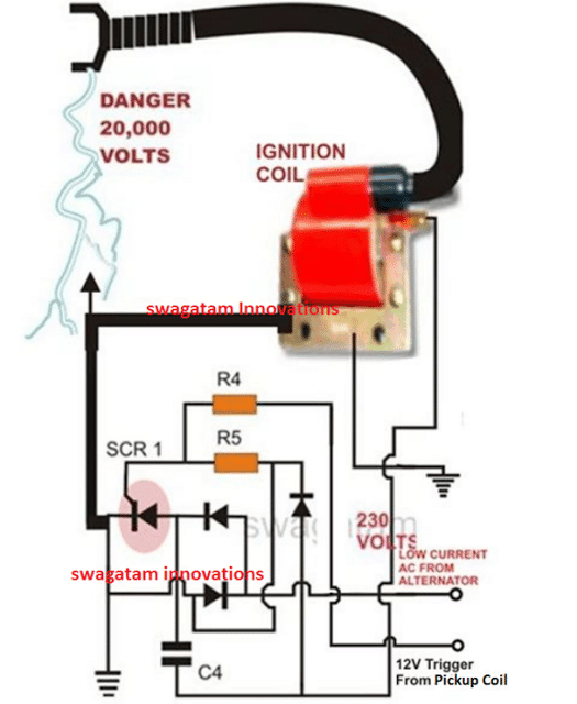
Capacitive Discharge Ignition (CDI) Circuit for Two-Wheelers

PCB Design

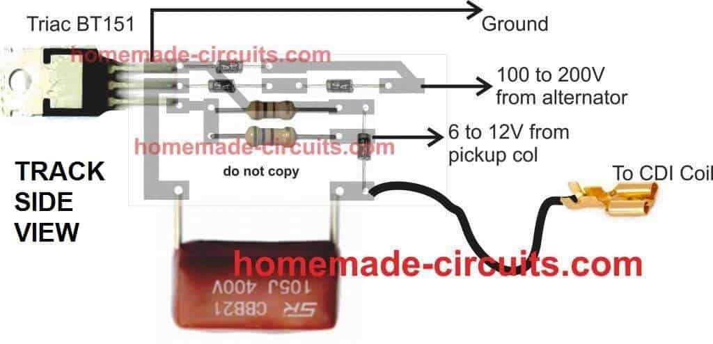
CDI ignition PCB design

CDI Circuit using an SCR, a few Resistors and Diodes

Referring to the above capacitor discharge ignition circuit diagram, we see a simple configuration consisting of a few diodes, resistors, a SCR and a single high voltage capacitor.

The input to the CDI unit is derived from two sources of the alternator. One source is a low voltage around 12 volts while the other input is taken from the relatively high voltage tap of the alternator, generating around a 100 volts.

The 100 volts input is suitably rectified by the diodes and converted to 100 volts DC.

This voltage is stored inside the high voltage capacitor instantaneously. The low 12 voltage signal is applied to the triggering stage and used for triggering the SCR.

The SCR responds to the half wave rectified voltage and switches the capacitors ON and OFF alternately.

Now since the SCR is integrated to the ignition primary coil, the released energy from the capacitor is forcibly dumped in the primary winding of the coil.

The action generates a magnetic induction inside the coil and the input from the CDI which is high in current and voltage is further enhanced to extremely high levels at the secondary winding of the coil.

The generated voltage at the secondary of the coil may rise up to the level of many tens of thousands of volts. This output is appropriately arranged across two closely held metal conductors inside the spark plug.

The voltage being very high in potential starts arcing across the points of the spark plug, generating the required ignition sparks for the ignition process.

Parts List for the CIRCUIT DIAGRAM

R4 = 56 Ohms,
R5 = 100 Ohms,
C4 = 1uF/250V
SCR = BT151 recommended.
All Diodes = 1N4007
Coil = Standard two-wheeler ignition Coil

The following video clip shows the basic working process of the above explained CDI circuit. The set up was tested on table, and therefore the trigger voltage is acquired from a 12V 50Hz AC. Since the trigger is from a 50Hz source, the sparks can be seen arcing at the rate 50Hz.

You'll also like:

  • block digram compressedVehicle Parking Lot Counter Circuit
  • autorollupordownmodul BROKENHow to Make a Car Power Window Controller Circuit
  • park2BlightDarkness Triggered Car Safety Park Light Circuit
  • mainsremoteBluetooth Car Ignition Lock Circuit – Keyless Car Protection

Filed Under: Automobile Electronics Tagged With: Capacitive, CDI, Discharge, Ignition, Simple

About Swagatam

I am an electronics engineer and doing practical hands-on work from more than 15 years now. Building real circuits, testing them and also making PCB layouts by myself. I really love doing all these things like inventing something new, designing electronics and also helping other people like hobby guys who want to make their own cool circuits at home.

And that is the main reason why I started this website homemade-circuits.com, to share different types of circuit ideas..

If you are having any kind of doubt or question related to circuits then just write down your question in the comment box below, I am like always checking, so I guarantee I will reply you for sure!


Previous Post: « Mains AC Short Circuit Breaker/Protector – Electronic MCB Circuit
Next Post: How to Make Car LED Chasing Tail Light, Brake Light Circuit »

Reader Interactions

Questions & Answers

Total Posts: 348
Newest Oldest
Hugo Mercurio Nicolucci
July 13, 2026 • 1 month ago #209864

Hi , here Hugo from Brasil, how are you.
I have a Kawasaki KX 250 cc 2 stroke year 1988 with no spark.
I measure de peak of the coil in flywhel an mesasure 150 Volts peak. In the trigger coil 2 Volts peak, correct?
I measured too, the resistance and impedance of the coils and are acordgny to especifications of Kawasaki manual.
how can I test the CDI.
I`m Tecnical in electronics and I have a complete Laboratory to test electronic devices.
Thnk you in advance.
Hugo

Reply
SwagatamAdmin
July 14, 2026 • 1 month ago #209893

Hey, you can test your CDI or CDI coil, using the following setup, let me know if you have any confusions:
piaggio CDI circuit

Reply
Luan
April 16, 2026 • 4 months ago #205184

Hello Sir.
Thanks for the answer. If I apply your scheme, TCI with three transistors with a point, I think it should definitely work, but I don’t know how it will be powered.
I believe with the excitation coil (alternator) or I need to add a voltage regulator and battery. If so, what current should I calculate?
Thanks in advance.

Reply
SwagatamAdmin
April 17, 2026 • 4 months ago #205226

Thanks Luan,
which 3 transistor circuit are you referring to, I cannot see any 3 BJT circuit in the above article?

Reply
Luan
April 15, 2026 • 4 months ago #205102

Hello Sir.
I have an Aprilia 50cc motorbike, with a Minarelli V1 engine and a Bosch crankshaft, with 2 coils, 6 volts and an alternator. It also has a point + capacitor. There is no HT coil. The alternator is burnt out with 12,000 turns and I can’t find it. They tell me that it is very difficult to modify. Can you help me with any suggestions. Respect!

Reply
SwagatamAdmin
April 16, 2026 • 4 months ago #205157

Hi Luan,
The original 12,000-turn ignition coil is difficult to replicate accurately. The best option is to convert the system to a CDI-based ignition using an external ignition coil and pickup sensor. This will be more reliable and easier to maintain.

Reply
Parveen
February 22, 2026 • 6 months ago #201516

Hi Swagatam
Could you please help me for driving the deuterium Lamp.

Reply
SwagatamAdmin
February 22, 2026 • 6 months ago #201527

Hi Parveen,
Can you please show the datasheet of the lamp, then I can design the full circuit diagram for you…
Or you can just provide the main specifications of the lamp, that will also do…

Reply
Russ R.
October 29, 2025 • 10 months ago #189388

Need data regarding build of CDI circuit. Desired no reverse in primary coil, and need method of shutting off DC SCR. No second scr or triac. There is charging low value inductor only for CDI capacitor of 2uf. How to stop discharge of power supply filter capacitor to add to the 2uf during main large primary coil discharge. Is separate coil inductor and blocking diode needed for shut off?

Reply
SwagatamAdmin
October 30, 2025 • 10 months ago #189428

You can build the CDI exactly as discussed in the above article, nothing needs to be added or removed…it is a thoroughly tested design, it has been tested on 1000s of 2/3 wheeler automobiles

Reply
Altaf
February 6, 2026 • 7 months ago #200490

Hi Swagatam I appreciate your work I’m interested. I will be highly appreciate your advices. Let me have a some time to study. I’m 75+ y. o. Thanks Gentleman

Reply
SwagatamAdmin
February 6, 2026 • 7 months ago #200516

Hi Altaf, no problem at all… wish you all the best with the project…

Reply
Jason Sagaci
December 11, 2025 • 8 months ago #195151

Dear sir;
What is the power limit of the 100, and 56 Ohm resistors respectively?
Thank you

Reply
SwagatamAdmin
December 11, 2025 • 8 months ago #195158

Hi Jason, they both can be 1 watt rated or above…

Reply
Harun
September 24, 2025 • 11 months ago #186322

Greetings Swagatam

I have two coils on an outboard motor, that needs a CDI unit, because it’s a 2-stroke motor, with 2 sparkplugs. Will this CDI circuit work? Can I connect both the coils to this one circuit?

-Harun

Reply
Ermen
April 3, 2026 • 5 months ago #203981

only if you want to trash your engine. if you use te same CDI, your piston cylinders will get fire at the same time, this would most assuredly not run and may even break your crankshaft, there are millions of Artificial Intelligent spider bots spreading disinformation on the internet.

Reply
SwagatamAdmin
September 24, 2025 • 11 months ago #186324

Hi Harun, this CDI is a universal automobile CDI which should work in all types of petrol or diesel engines, provided the trigger pulse input is correctly timed…..

Reply
Harun Krak
October 23, 2025 • 10 months ago #188883

Hi Swagatam

I have built the CDI circuit, and I wanted to know, can you give me some instructions as how to test, with a multimeter, that I have constructed the circuit correctly? Because I’ve tried connecting it to my engine, and nothing happened.

Reply
SwagatamAdmin
October 24, 2025 • 10 months ago #188934

Hi Harun,
You must first test the circuit on your work bench, and then install in your vehicle.
Please do the following set up and confirm the working of the circuit first:
CDI test set up

Reply
Donald Ball
May 31, 2025 • 1 year ago #179079

HI, I would like to know the diffrents of a 2 stroke AC CDI to a 4 stroke AC CDI engine? I have a Wisconsin s 14 d engine with the 4 pin AC CDI ign., do you have a CDI circuit diagram for this engine? I tryed a 2 stroke 4 pin AC CDI on this engine and had spark but no run. Any help thanks

Reply
SwagatamAdmin
June 2, 2025 • 1 year ago #179247

Yes that’s correct! 2-stroke CDI gives spark every rotation but 4-stroke engine needs spark only every alternate rotation, during compression stroke only. If you put a 2-stroke CDI on a 4-stroke engine then it may give spark at wrong time (like during exhaust stroke), so engine may fire once but not run continuously.

basically both 2-stroke and 4-stroke engines can use AC type CDI units but the timing and trigger pulse requirements are not same. Even if the pinouts look same and spark comes, the engine might not run, just like what happened to you.

Reply
Donald Ball
June 2, 2025 • 1 year ago #179367

Thanks, Ok the trigger palse is what tells the condenser to release the stored energy to the ignition coil. The timming is fixed to fire BTC on both 2 and 4 stroke engines, what is the diffrents in the AC CDI ?

Reply
SwagatamAdmin
June 3, 2025 • 1 year ago #179603

AC and DC CDIs both work in the same way, there job is to discharge a high voltage capacitor to generate a spark. AC CDI uses high voltage AC from the alternator, whereas DC CDI can use 12V from battery and boost it to generate a high voltage pulse using an internal transformer.

Reply
Donald Ball
June 6, 2025 • 1 year ago #179956

Thanks, What I wanted is to know what’s inside the AC CDI box that makes 2 stroke and 4 stroke diffrent? To make a CDI for a Wisconsin engine, would I have to be an wisconsin engineer?

Reply
SwagatamAdmin
June 6, 2025 • 1 year ago #179995

inside AC CDI for 2-stroke and 4-stroke almost all components are same, they have high voltage capacitor, SCR, trigger circuit, etc. What makes them different is mostly how the trigger timing is set up because 2-stroke needs spark every 1 turn, 4-stroke needs spark every 2 turns. Some CDIs are smart and skip every second trigger but most just follow whatever trigger you give. So if you use a 2-stroke CDI on 4-stroke engine then it may give spark on exhaust stroke also (called wasted spark), not harmful but not best. About your Wisconsin engine, you do not need to be a Wisconsin engineer, you just need to check how many magnets on flywheel, where is the pickup coil, what spark timing is needed and then match a CDI to work with that pulse. You can use ready-made CDI or even build one if you know SCR circuits.

Reply
Sunil Nikam
November 30, 2024 • 2 years ago #166292

like to make a circuit CDI discharge system.
discharge will be at 2000VDC , 12 jule power , 2-3 discharges per sec.
Input voltage 220 V /120 V AC,

please comment

Reply
SwagatamAdmin
November 30, 2024 • 2 years ago #166297

Sure, you can try the above CDI circuit, the sparking frequency will depend on the triggering frequency at the “pickup coil” input terminal of the circuit…

Reply
Raimo Kananen
October 2, 2024 • 2 years ago #162331

kondensaattori sytyksen lisääminen esim boch käjettömäänn sytys järjestelmään? Palkoko maksaa.MSD A6 on kallis voiko vastaavan tehdä halvemmalla.

Reply
John
September 23, 2024 • 2 years ago #161399

greetings Swagatam
I made this once but it didn’t work, I think I made a mistake somewhere,I wanted to know if this circuit is CDI, DC or AC?
thanks for sharing

Reply
SwagatamAdmin
September 24, 2024 • 2 years ago #161478

Hi John, did you supply the 100V to 200V high AC voltage and the 12V pulsed voltage to the inputs of the CDI circuit as shown in the diagram?
Both of these voltage simply needs to be pulsed, it doesn’t matter whether they are AC or DC, they should be intermittent and not continuous, that’s all…please let me know.

Reply
John
October 15, 2024 • 2 years ago #163483

Hi Swagatam thanks for reply,
When I made it again I saw that it worked very well, I must have been wrong before, it was really great, thanks
Can you share CDI racing or DC circuit?
And instead of bt 151 thyristor, can I use z44 MOSFET or 2n 3055 transistor?

Reply
Julian Flores
April 13, 2025 • 1 year ago #172634

how can I make a simple unit to trigger a cop coil on my motorcycle

Reply
SwagatamAdmin
October 16, 2024 • 2 years ago #163520

That’s great John, glad it is working now!

For a DC CDI you can refer to the following article:

https://www.homemade-circuits.com/make-this-enhanced-capacitive-discharge/

No, I don’t think the SCR can be replaced with a transistor, SCR looks more suitable for this specific application.

Reply
Mark
July 17, 2024 • 2 years ago #154957

helow sir i wish to have a 4pin cdi diagram..can riv to high rpm hopefully

Reply
SwagatamAdmin
July 17, 2024 • 2 years ago #154958

Hi Mark, can you please provide the specifications of the 4 pins, I will try to help!

Reply
John Doe
March 3, 2024 • 2 years ago #149621

Hi, have you tried using this circuit with a square wave DC pulse as the trigger? I am using a similar design, although slightly simpler, only a current limiting resistor to the gate pin instead of a divider and slightly higher capacitance on the capacitor, but basic idea still remains. However I ran into a weird issue of it not revving past 1500 rpm.

Reply
SwagatamAdmin
March 3, 2024 • 2 years ago #149634

Hi, It doesn’t matter whether the triggering pulse is a square wave or a sine wave, the SCR will trigger once the gate voltage crosses the 0.7V mark.
You can try the above design and check if it makes any difference.

Reply
Ken Yegge
March 8, 2024 • 2 years ago #149901

Cool I just blew out my cdi on moped and I have no income but I got ability and some junk parts I can salvage all I needed was your information to build replacement cdi and get going again. And I noticed your section HHO which I believe has to do with hydrogen if I’m correct I want to make all my power come from hydrogen and the greatest fuel in world only thing I’ve been stifled by is coming up with easy free supply for electrolyte. But your just the help inspiration I needed book marked¡¿¡

Reply
SwagatamAdmin
March 8, 2024 • 2 years ago #149914

Sure, I can help. If you have CDI related questions you can ask them here. For the HHO related questions you can feel free to comment under the following article:
https://www.homemade-circuits.com/how-to-use-hho-fuel-cell-in-automobiles/

Reply
Ken Y
March 8, 2024 • 2 years ago #149939

Ya know I looked at that circuit and thought it looks to me like it could take reverse 20 volt except cap and I was right but the regulator was bad and I believe it was in need replaced b4 cool ty for simple circuit

Reply
manjeeth
January 14, 2024 • 3 years ago #148556

can i use MOSFET irfz44n insted scr by151

Reply
SwagatamAdmin
January 14, 2024 • 3 years ago #148558

No, MOSFET cannot be used in place of SCR.

Reply
nick carper
November 13, 2023 • 3 years ago #146804

Sir, Is there a way to modify or add a timing adjustment to the cdi circuit. auto or manual??? thanks Nick

Reply
Nick Carper
November 15, 2023 • 3 years ago #146940

Sir, question about how to wire the cdi,, wire that goes to the alternator.. my magneto, has 3 wires coming from engine alternator coil, 18 total coils ,with. six,6 coils per wire 2011 suzuki savage 650 motorcycle. they run to a rectifier . How do I connect the single wire coming from cdi to the 3 wire magneto??? hope i made this clear.. thanks for any assistance. Nick in Missouri.

Reply
SwagatamAdmin
November 15, 2023 • 3 years ago #146958

Hi Nick,
As far as I know, you will need to check the voltages from the respective alternator wires with respect to the body ground of your motorcycle. You may have to use an AC voltmeter to check this.
The wire that produces anything above 100V AC can be connected to the CDI 230 V input.
The 12V trigger input from the CDI must be connected with the pickup coil output of your motorcycle.
I think a good qualified motor mechanic or electrician will be able to guide you better regarding the relevant connections.

Reply
Nick carper
November 16, 2023 • 3 years ago #147042

Thanks for a swift reply. Great job. I Understand, I think I can figure it out. 5 plus. Nick

Reply
SwagatamAdmin
November 16, 2023 • 3 years ago #147054

Glad I could help!

Reply
SwagatamAdmin
November 13, 2023 • 3 years ago #146809

Hi Nick, sorry, in this basic CDI circuit design, timing adjustment cannot be added.

Reply
nick carper
November 14, 2023 • 3 years ago #146869

thank you so much for your circuits and your help. Nick Carper

Reply
PADMAHARSHA
November 1, 2023 • 3 years ago #146634

Dear all
can you peaple give me a DC CDI Circuit for 200cc motor bike it will be very helpful
Thank you all for informations.

Reply
SwagatamAdmin
November 1, 2023 • 3 years ago #146635

Hello Padmaharsha,
you can build the CDI circuit explained in the above article, it is perfectly suitable for you bike…

Reply
Tim
October 30, 2023 • 3 years ago #146580

Hi Swagatam,

Thank you for your very useful explanation of the CDI circuit. I have a 1978 Johnson two cylinder two stroke outboard and I think there is a fault with the CDI unit. I have taken the unit apart and exposed the circuit board (which unfortunately caused some damage to components removing the protective resin).

I am trying to find out what the components might have been to recreate the circuit with replacement components and wondered if you might be able to help as your circuit looks smaller but similar. If you would be willing to take a look could I send you a photo of my circuit board to see what you think? Thank you in advance for all the useful information

Reply
SwagatamAdmin
October 30, 2023 • 3 years ago #146582

Thank you Tim,
The above explained CDI design is tested on across thousands of two wheelers and auto rickshaws in India, in fact I have manufactured 1000s of these units and sold them in the local market without issues.
So you can replicate the above circuit and use it for your motor bike.
It could be actually very difficult for me to check the image of your CDI and suggest th component values or create a circuit diagram.

Reply
John Budd
June 30, 2023 • 3 years ago #143820

I have a Husqvarna 285CD chainsaw. It is in very good condition but the CDI ignition has failed. It is now impossible to obtain a new stator plate with all the coils etc. there are only two coils, one for charging the capacitor and the other to supply the HV for the spark. There is no extra coil or sensor to trigger the SCR/thiristor. I wish to find out how the triggering is done and a circuit to match. Both coils I have appear to be ok. The rectification and triggering are encased in a solid block of resin. I would like to remove the resin block and construct a replacement. Any help , circuit diagram, ideas, etc. would be very much appreciated. Johnl

Reply
SwagatamAdmin
July 1, 2023 • 3 years ago #143832

Sorry, I have no idea regarding how the above CDI circuit can be implemented in your application without a pickup coil trigger voltage for the SCR.

Reply
Nick. Carper
June 16, 2023 • 3 years ago #143474

I have a cdi for 2001 650cc savage motorcycle. It will supply a single spark and than quit, till I cycle ignition off and than back on for a single spark repeating each attempt to start. Coil. Plug, igniter and wiring have all been replaced. Any hint or answers would be appreciated. Thanks, new cdis from Suzuki are 700. Dollars . Thanks Nick carper.

Reply
SwagatamAdmin
June 17, 2023 • 3 years ago #143480

The CDI will require a continuous source of pulses from the pickup col to keep the ignition sparks alive and kicking. Is your pickup coil providing the required pulses for this?

Reply
nick carper
November 13, 2023 • 3 years ago #146806

thanks for your answers to my inquiry. Yes I have a trigger coil that is working … Suzuki 2011 savage 650 single cylinder.

Reply
Mimo
May 19, 2023 • 3 years ago #142681

Hello. I made a CDI according to your scheme but I do not know why my R4 burns. Please help???

Reply
SwagatamAdmin
May 19, 2023 • 3 years ago #142682

The pulse voltage to R4 gate resistor is supposed to come from the pickup coil which has very low current. What is your source for the 12V signal?
If it is from a power supply, decrease the voltage to 5 V or increase the R4 value to any value between 100 ohms and 1K

Reply
Mimo
May 19, 2023 • 3 years ago #142689

I use for yamaha YZ 125 1993. Tomorrow I will measure the voltage on the 
pickup coil 

Reply
SwagatamAdmin
May 20, 2023 • 3 years ago #142694

OK, no problem!! Also you can feel free to increase the resistor value upto 470 ohms.

Reply
Andrew
June 23, 2023 • 3 years ago #143623

Hello Sir. I have the same problem. My 12v source is from pulse generator with 20.9 ohms 14.75mH coil. It burns when I reach 4000RPM.

Reply
SwagatamAdmin
June 23, 2023 • 3 years ago #143626

Hello Andrew, the above CDI circuit has been extensively tested and used on Indian motorcycles and auto-rickshaws without any issues. So the CDI components and diagram is absolutely correct.

It can be difficult for me to troubleshoot your issue without checking it practically.

Reply
Dan
March 31, 2023 • 3 years ago #141522

Dear Mr Swagatam.

I am not an expert in electronics. Need your advice please,

I own a small (Mosa msg chopper) 2 stroke engine welder and I’m having problems getting back the spark.

The thing is that this engine has an AC type of ignition which I’m not used to work on.

I say AC cdi because the engine does not have a battery or any sign of a direct current/wire going to the cdi unit. Please correct me if I’m wrong.

I daily work on mopeds of which most cdi ignition systems are built with charge capacitor or exciter coils and pick up/trigger coils located as two different coils on their own spot under/beside the flywheels.

This Mosa engine has only 2 coils under the flywheel/magnets:

1.The exciter coil or charge capacitor coil which function is to keep the engine sparking/running.
(I came to the understanding that the exciter coil and trigger/pickup coil are
fabricated as 2 functions in one coil)

2.The electromagnet coil which function is for WELDING ONLY. (not important for
spark)

The cdi unit has 4 terminals indicating the wire colors and their functions.

charge capacitor coil (green)pulse/ trigger (red)main coil (blue)ground (black)
The exciter coil or charge capacitor coil has two terminals going to the cdi unit. A red wire and a green wire.

The red wire is for pickup/pulse and the green wire is for the charge capacitor or exciter as shown above.

This is my first experience with this type of ignition of which I experience no pulse/trigger coil internally/externally visible.

The main coil which goes to the spark plug is OK.
I tested it on my moped and gives a nice blue spark.

My goal is to rewind the exciter coil but the engine manual only specifies the resistance for the electromagnet coil (2.9ohms) which is for welding function and not for spark.

There is no info on the exciter coil and it’s resistance.
I dissembled the wire from the exciter coil and opened up the cdi unit which I pretty much damaged some parts of but I was planning to buy a new cdi unit THAT FITS THIS TYPE OF CDI anyway.
The exciter coil is not available in stores so I will need to rewind it.

Please your advice on rewinding the exciter coil and it’s resistance.

If you would like to see some photos of the parts and/or the engine then I can send them to you via email or whatsapp.

mosa.com.au/inventory/manuals/MSG%20CHOPPER.pdf shows the engine manual.

Regards,
Dan

Reply
SwagatamAdmin
March 31, 2023 • 3 years ago #141523

Hi Dan,
Sorry, I have no idea regarding the rewinding process of the exciter coil, because I have never come across practically with these types of systems. I hope someone else in this forum might be able to provide some help.

Reply
Kitt
March 23, 2023 • 3 years ago #141283

Dear Swagatam, Im thinking of using this circuit as the electrocution supply for the mosquito killer circuit you did in another link. How can I limit it to only 3500V and 9mA current? Thank you.

Reply
SwagatamAdmin
March 23, 2023 • 3 years ago #141292

Hi Kitt,
In the PCB schematic you can see one terminal labelled as 100 to 200V AC from alternator. You can experiment with this AC voltage and reduce it to 24V AC in order to step down the output voltage from the CDI coil to the desired limits. Just as the AC voltage the current can be also reduced at this terminal.

Reply
Kitt
March 24, 2023 • 3 years ago #141313

Thank you vmuch. I assume when you put 200 volts AC, you wil get 20000 volts CDI output. so if its 100 VAC, goes down to 10k volts, and 24VAC goes to 2400 VAC. First there is a way to measure the Voltage using any voltmeter, etc? Or does the CDI have specs printed to show how much is the multiplier to the output? 2ndly, since we decrease the voltage to say 2400-3500V, what space distance would you think the mesh screen should have between each other? Thanks again 🙂

Reply
SwagatamAdmin
March 24, 2023 • 3 years ago #141320

Your assumptions are correct, however I cannot confirm the exact output voltage that you may get using a 200V or a 24V, from the CDI coil.
One way of determining it is to connect 5nos of 1M resistors in series across the CDI output and measure and verify the voltage across these resistors using resistive divider formula.
The distance between the mesh wiers could be around 3 to 5 mm.

I think I have a related article posted in this blog which you can see in the following link:

https://www.homemade-circuits.com/mosquito-killer-circuit/

Reply
Kitt
March 24, 2023 • 3 years ago #141326

Thank you again. Got it with the mesh. Regarding the 5nos 1M ohm resistors..so I will have to measure using voltmeter in 1 resistor. So the “20k volts” would be divided through the 5 resistors effectively giving 4000volts each. Can we measure using ordinary voltmeter? Another question is if I intend to use 24VAC up to 110VAC, will the specifications or values of the components in your circuit be changed? and what are they incase I use 110VAC and/or 24VAC? Thank you again 🙂

Reply
SwagatamAdmin
March 24, 2023 • 3 years ago #141329

I don’t think the total voltage can be determined by measuring the voltage across 1 resistor. It looks much more complex than that. So the resistor method might not work. If you have a voltmeter which can measure upto 5000V then you can simply use the meter to measure the output directly. Remember the output will be pulsed, so the meter will show only the average value of the pulsed DC. For example if the input 12V trigger pulse has 50% duty cycle then the voltmeter will show 50% of the actual output voltage from the CDI coil.
The circuit will not need any changes for input AC voltages ranging between 12V and 200V AC.

Reply
Kitt
March 25, 2023 • 3 years ago #141341

Ok Thank you Swagatam! 🙂

Reply
SwagatamAdmin
March 25, 2023 • 3 years ago #141348

You are welcome Kitt.

Reply
Kitt
March 25, 2023 • 3 years ago #141337

Sorry, forgot to ask. Do I have to put the 680 ohms resistor in between R4 and Trigger as shown in your video? what is its purpose? Thanks.

Reply
SwagatamAdmin
March 25, 2023 • 3 years ago #141346

You can add that resistor for an increased safety for the SCR…the value can any value between 470 ohms and 1K.

Reply
Kitt
March 25, 2023 • 3 years ago #141336

Ok great! Very clear and well said. Ok. I will make the 110VAC (60hz) as my trigger pulse. anyway, the mosquitoes still will get electrocuted around 10000VAC. Im doing this to replace the High Voltage transformer that I use (very costly due to shipping 🙂 and if damaged, u have to replace cause its hard to rewind. Thanks again Swagatam! More power to you and on what you do! 🙂 Namaste!

Reply
SwagatamAdmin
March 25, 2023 • 3 years ago #141345

Thank you Kitt.,
The trigger pulse should be 12V DC pulse and the AC input can be a 110V AC.
Yes, certainly 10000V should be more than enough to electrocute the mosquitoes

Reply
ampmann
March 1, 2023 • 3 years ago #140632

I do not understand…4 diodes in the picture but 3 in the schematic.
Which one is correct?
Shunt kickback voltage? Diode from cap output to ground.

Reply
SwagatamAdmin
March 1, 2023 • 3 years ago #140635

The PCB layout picture and the schematic diagram, both have 4 diodes.

Reply
Nick carper
February 18, 2023 • 4 years ago #140329

Need a cdi design for 650 cc s40 suzuki motorcycle. 2001 single cylinder. Thanks Nick

Reply
SwagatamAdmin
February 18, 2023 • 4 years ago #140330

I think you can try the same CDI circuit explained above. It should work.

Reply
Nick carper
February 18, 2023 • 4 years ago #140342

Thanks Nick

Reply
Isidore
January 17, 2023 • 4 years ago #139017

Hi, in your cdi circuit, why do you put a diode who is shorting
the negative part of the AC wave from the alternator ?

Reply
Chris
March 7, 2023 • 3 years ago #140819

Because as stated, it is half wave rectified DC. So it is only rectifying half of the waveform. The voltage is high enough that half wave pulsed DC is sufficient to charge the cap. and we only need a small DC pulse from the trigger coil to fire the SCR. So long as the trigger provides the I(gt) that the gate on the SCR needs (typically only like 0.5-50mA), it will latch the SCR and discharge to the primary of the ignition coil.

Reply
SwagatamAdmin
January 17, 2023 • 4 years ago #139024

Hi, it is not my design, it is the original design taken from rickshaw CDI.

Reply
Geoff P
September 17, 2022 • 4 years ago #133302

Hi Swagatam
I have a 1960 vintage CDI that resembles similar DIY products usually marketed by Tandy or Jaycar for the hobby market, except this one has been commercially produced and after 60 years has failed.

Enquiries suggest that it is the capacitor and that the early capacitors failed because they ‘dried out’, is this still a problem.

Geoff P

Reply
SwagatamAdmin
September 17, 2022 • 4 years ago #133303

Hi Geoff,
60 years is a long time, and we can’t expect more from an electronic device.
CDI circuits don’t use an electrolytic capacitor for the capacitive discharge, rather a PPC a metallized PPC is used which do not have electrolyte inside. So “drying out” of the capacitor may not be possible. Nevertheless, wearing out of the capacitor may be possible due to overuse. Another part that can go faulty is the SCR which is subjected to a huge amount of stress during the charge/discharge switching process

Reply
John Lloyd
July 10, 2022 • 4 years ago #131475

Hi Swagatam
I am from Philippines and I have an interest about this topic can I use your diagram as a reference in our research paper to support my argument that there’s an AC CDI in the ignition system of the motorcycle. I ensures that this will be use only for educational purposes.

Please advise.
Best regards John Lloyd

Reply
SwagatamAdmin
July 10, 2022 • 4 years ago #131480

Hi John,

No problems at all. You can feel free to use the concept in your papers.

Reply
Desmond
December 22, 2021 • 5 years ago #107952

Hi Swagatam
First Let me say I love your site and have bookmarked it.
I have been looking for a long time for a simple CDI set up to go between the set of points, and the existing ignition coils on my positive earth classic motorbike.
Can any of these circuits be redesigned to take positive earth/ frame wiring.Obviously all the Diodeswill need to be turned arround but I’m not confident about the other components,
Please advise.
Best regards Desmond Tutu

Reply
SwagatamAdmin
December 22, 2021 • 5 years ago #107984

Thanks Desmond, glad you liked and bookmarked this site!

I don’t think changing the diode polarity will make the design compatible with a positive earth vehicle. It looks more complex than that, because we have an SCR whose polarity will also matter. Actually I am unable to find an appropriate solution at the moment. If I happen to find anything useful will surely let you know.

Reply
andrew smith
August 20, 2021 • 5 years ago #95033

can you please show and explain a circuit diagram for a scooter cdi that has the ability for advancing the ignition sparking for when the engine speeds up

Reply
SwagatamAdmin
August 20, 2021 • 5 years ago #95058

Sorry, I do not have a CDI circuit with an ignition advancing feature

Reply
Søren
August 12, 2021 • 5 years ago #94037

@Marcelo
Sorry, but no such luck.
.
D5 shunts inductive kickback from the ignition coil to ground.
.
D3 ensures that the left side of the 1.5uF cap will never go more than the voltage drop of D3, around 0.7V negative.
.
D4 a zener diode, sets how negative the gate of T2 can go, when the pickup coil goes negative.
.
Poorly designed circuit, or a case of the “money guys” wanting the engineers to cheapen a better design.
.
Hope it helps, but I can’t see any date on the posts (???), or a direct way to reply to a particular post.
.
/Søren

Reply
Marcelo
April 30, 2021 • 5 years ago #88880

Hi Swagatam!
In the circuit of the link below, does diode D3 and D4 have a function to partially recharge the capacitor? I ask this because the primary of the coil generates oscillations after the spark is generated, can it be reused?

suzuki+rm85+cdi

Reply
SwagatamAdmin
April 30, 2021 • 5 years ago #88889

Hi Marcelo, sorry I can’t figure out the function of the diodes…

Reply
View Older Comments

Need Help? Please Leave a Comment! We value your input—Kindly keep it relevant to the above topic! Cancel reply

Your email address will not be published. Required fields are marked *

Primary Sidebar


Categories

  • Arduino Projects (95)
  • Audio and Amplifier Projects (134)
  • Automation Projects (18)
  • Automobile Electronics (104)
  • Battery Charger Circuits (90)
  • Datasheets and Components (109)
  • Electronics Theory (150)
  • Energy from Magnets and Earth (41)
  • Games and Sports Projects (11)
  • Grid and 3-Phase (20)
  • Health related Projects (27)
  • Home Electrical Circuits (13)
  • Indicator Circuits (16)
  • Inverter Circuits (100)
  • Lamps and Lights (163)
  • Meters and Testers (72)
  • Mini Projects (28)
  • Motor Controller (68)
  • Oscillator Circuits (30)
  • Pets and Pests (15)
  • Power Supply Circuits (91)
  • Remote Control Circuits (50)
  • Security and Alarm (65)
  • Sensors and Detectors (107)
  • SMPS and Converters (46)
  • Solar Controller Circuits (62)
  • Temperature Controllers (44)
  • Timer and Delay Relay (50)
  • Voltage Control and Protection (44)
  • Water Controller (37)
  • Wireless Circuits (31)


Circuit Simulator

circuit simulator image


Subscribe to get New Circuits in your Email


Other Links

  • Privacy Policy
  • Cookie Policy
  • Disclaimer
  • Copyright
  • Videos
  • Sitemap

People also Search

555 Circuits | 741 Circuits | LM324 Circuits | LM338 Circuits | 4017 Circuits | Ultrasonic Projects | SMPS Projects | Christmas Projects | MOSFETs | Radio Circuits | Laser Circuits | PIR Projects |


Recent Comments

  • Swagatam on Electronic Circuit Projects, Tutorials, and Practical Engineering Solutions
  • Swagatam on 50 Watt Sine Wave UPS Circuit
  • Tom Sendelbeck on Electronic Circuit Projects, Tutorials, and Practical Engineering Solutions
  • Alireza.Moghaddam on 50 Watt Sine Wave UPS Circuit
  • Swagatam on Simple Walkie Talkie Circuit

Social Profiles

  • Twitter
  • YouTube
  • Instagram
  • Pinterest
  • My Facebook-Page
  • Stack Exchange
  • Linkedin

© 2026 · Swagatam Innovations