The circuit presented here is for a DC-CDI which are used in motorcycles. A DC-CDI is the one in which the high voltage (200-400VDC) is converted from 12V supply voltage.
Researched and Submitted by: Abu-Hafss
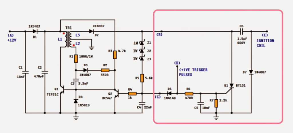
Studying the circuit, we see that it has two parts i.e. the smps CDI unit, enclosed in the pink box and the remaining circuit on the left is high voltage converter.
The working of the CDI may be found in this article.
The circuit on left is a high voltage converter based on a blocking oscillator. The components Q1, C3, D3, R1, R2, R3 and transformer T1 forms the blocking oscillator.
L1 is the primary coil and L2 is the feedback coil. C1, C2 and D1 are DC voltage smoothing components.
How it Works
When the circuit is powered on, R3 provides forward bais to the base of Q1. This turns on Q1 and current starts flowing thru the primary coil L1 of the transformer.
This induces voltage in the secondary or the feedback coil L2.
The red (phase) dots in the transformer symbol indicates that the phase of the voltage induced in L2 (and L3) is shifted 180°.
Which means when the bottom side of L1 is going negative, the bottom side of L2 will be going positive.
The positive voltage of the L2 is fed back to the base of Q1 thru R1, D1, R2 and C3. This causes the Q1 to conduct more hence, more current flows thru L1 and ultimately more voltage is induced into L2.
This causes L1 to saturate very rapidly which means no more changes in magnetic flux and hence no more voltage is induced into L2.
Now, C3 starts discharging through R3 and finally Q1 is switched off. This stops the current flow in L1 and hence the voltage across L1 comes to zero.
The transistor is now said to be "blocked". As C3 gradually loses its stored charge, the voltage on the base of Q1 begins reverting to a forward-bias condition by means of R3 thus switching on Q1, and hence the cycle is repeated.
This switching of Q1 is very fast such that the circuit oscillate at quite high frequency. The primary coil L1 and secondary L3 forms a step-up transformer and thus a fairly high alternating voltage (more than 500V) is induced in L3.
To convert it to DC a fast recovery diode D2 is deployed.
The zeners, R5 and C4 forms the regulator network. The sum of the values of the zeners should be equal to required high voltage to charge the CDI's main capacitor (C6).
Or alternatively a single TVS diode with desired breakdown voltage may be used.
When the output at the anode of D2 reaches the breakdown voltage (sum of zener values), the base of Q2 receives the forward bais and hence Q2 switches on.
This action steals the forward bais of Q1 thus stopping the oscillator temporarily.
When the output is dropped below the breakdown voltage, Q2 switches off and hence the oscillation resumes. This action is repeated very rapidly that the output is maintained slightly below the breakdown voltage.
The positive trigger pulse at point (D) in the CDI unit is also fed to the base of Q2. This is important to pause the oscillation because SCR U1 demands the current across its MT1/MT2 to be zero to be able to self-disconnecting.
Moreover, this increases power economy as all power supplied during discharging is wasted otherwise.
A special request from Mr. Rama Diaz to have multi CDI sections sharing a common HV converter circuit. Some parts of his request is quoted below:
Ok most engines these days don't have distributors anymore, they have a coil for each spark plug or in many cases have a dual post coil that fires 2 spark plugs at the same time, this is called "wasted spark" since only one of the two sparks is actually getting used each ignition event the other one just fires into the empty cylinder at the end of the exhaust stroke, so in this configuration a 2 channel CDi will run a 4cyl and 3 channel for 6cyl and 2 x 2 channel for v8 etc...
Almost all 4 stroke engines have 2 cylinders that are paired so only 1 coil (connected to 2 spark plugs) will fire at a time the other one/s will fire at the alternate ignition events driven by a separate trigger signal, Yes aftermarket ECU's have up to 8 completely separate ignition trigger signals....
yes we could just have 2 or 3 totally separate units but i would like to have everything contained in one unit if possible, and im thinking there would be some way to share some of the circuitry...
...so im thinking you could have one heavier current step-up section to provide the ~400v then have two (or 3) separate CDI coil driver sections with a separate trigger signal for each one to drive the coils independently....possible??
That way i could use 2 (or 3) dual post coils attached to 4 (or 6) spark plugs and have then all fire at the correct time in wasted spark configuration 🙂
This is exactly the way we often do it now inductively using simple transistor based ignitors but the spark strength is often not strong enough for turbo and high performance applications.
CIRCUIT DESIGN:
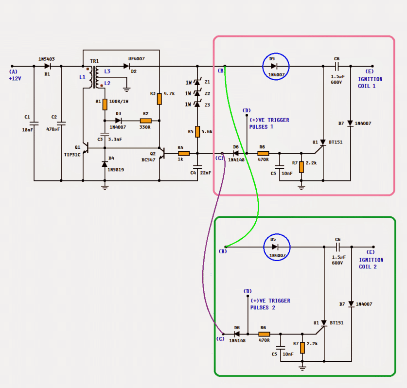
The entire circuit shown above can be used. The CDI unit enclosed in pink box can be used to drive one dual post ignition coil. For 4- cylinder engine, 2 CDI units; for 6-cyl, 3 CDI units can be used. When using multi CDI units, the diode D5 (encircled in blue) has to be introduced to isolate the C6 of each section.
TRANSFORMER SPECIFICATIONS:
Since the frequency of the oscillation is fairly (more than 150kHz), ferrite core transformers are used. A tiny 13mm EE core transformer can perfectly do the job but, handling such a small component might not be easy. A little bigger may be selected. Enameled copper wire 0.33 - 0.38mm for the primary (L1) and 0.20 - 0.25mm for the secondary L2 & L3.
The picture shows the bobbin's top view.
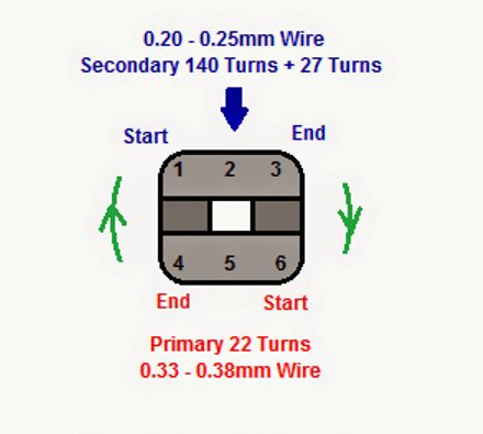
For primary winding, start from pin no. 6, wind 22 neat turns in the direction shown and end at pin no. 4.
Cover this winding with a transformer tape and then start the secondary winding. Starting from pin no. 1, wind 140 turns (in the same direction as that for primary) and make a tap at pin no. 2 and then continue another 27 turns and end at pin no. 3.
Cover the winding with tape and then assemble the 2 EEs. It is advisable to make an air gap between the 2 EEs. For this a tiny paper packing may be used. Finally use the tape to keep the 2 EEs united.


Questions & Answers
sir,what the value of z1,z2 and z3?can i change uf4007 with in4007?
Wah, please read the article, the details are explained in the article.
uF1N4007 could be a fast switching diode, not exchangeable with a 1N4007….you can try BA159 instead.
Rama DiazDecember 14, 2015 at 8:52 PM
Thank you!!!
This is brilliant and it will get built! I like the simplicity of just using a flipflop to drive the Hf generator that is nice! Unfortunately i will be away the next 2 months but as soon as i return i will start.
some questions; on a 6cyl with 3stage CDI this will operate at total spark outputs of up to 400Hz. Will the primary driver support this much draw??
Also Automotive coils connect using 2 wires normally, one is constant power and the other is the switched signal in this case should one just be earthed? and if so which one?
does the duration of the trigger signal matter? if so what should i set this to? (aftermarket ecus have this option)
Does the coil fire at the start of the signal or the end??
And lastly does it matter what type of capacitors are used?
Hi Rama
You are most welcome.
A single cylinder CDI-unit would work up to 9,000RPM or more without any need of ignition mapping.
400Hz means 400 x 60 = 24,000RPM, practically a 6-cyl. or 4-cyl. would never achieve such high RPM. It should be shared equally by each CDI-unit which means 8,000RPM per unit, though 8000RPM is practically quite high. Since all 3 CDI-units would be isolated, each capacitor C6 would get enough time to get charged and would not be much affected by the firing of other 2 capacitors. If you feel they are not working, you may change the values of C6 to 1µF/500V and/or reduce the charging voltage to 300V instead of 400V…….this will enable C6s to get charged more quickly.
Yes, the ignition coils have two terminals. The negative has to be earthed and the positive has to connected to point (E) of the CDI-unit.
As far as the duration of the trigger is concerned, I think it should be proportional to the RPM. A single cylinder CDI-unit would work up to 9,000RPM or more. For a 4-cyl. or 6-cyl. the RPM does not go that high therefore, even if the duration of the trigger is changed, it would not have any adverse effects.
The CDI-unit will fire as soon as positive (threshold) voltage is received at point (B) of the unit. I have successfully tested it with regular fluctuating 5V signals. For a squared-wave signal, of course, the unit will fire right at the beginning of the signal.
Yes, a good quality polypropylene capacitor should be used for CDI.
Excelent thank you!… yes 80000 rpm is quite high but that is rpm that many 6cyl race engine will use so i picked that as the practical maximum frequency.
I was more concerned about the current draw on the transformer and other primary components, but the capacitor charge time is also a factor.
Is it possible to configure it somehow so that the spark occurs at the end of the trigger signal? that is more in line with how most other ignition systems operate so the timing calibration will be configured to align more accurately that way.
One more question the voltage rating of the capacitors (c6) is that an ac rating or dc rating?? the same cap is often listed with very different values for each
regards
rama
First please, let me know the shape of the pulses from the ECU. See the figure in the link and let me know if it is A or B.
If it is type B then it will be easy to trigger the sparks at the end of the positive pulse. But if it is type A, it will be very difficult.
Since the capacitor has to be charged by 250-400VDC, the capacitors should be rated about 600VDC or more.
Swagatam Majumdar
hi, im realy interesting with your CDI idea. i dont have transformer according this article, but can you give me formulas or something to calculate how much turn to make transformator that produce 400v?
Hi Farhan,
Mr. Abu Hafss will be able to tell you about it better
Farhan Sahib
It is clearly mentioned in the article that the circuit is capable of producing more than 500VAC. In fact, I observed it to go to about 725VAC.
If you want 400VAC, simply select values of Z1-Z3. You can use 4 x 100V/1W zeners or 1 x 400V TVS diode.
The construction of the transformer is explained in details, in the article. Please read it thoroughly before starting the project.
Hi Im back so i am moving closer to building this project, my signal is selectable either like "A" @ 5V or it will be an inverse of A but without any voltage pullup, just signal going from open to LOW (never will it be like "B") So we can use either one but it is important that the spark action always happens at the end of the signal.
Oh also i have full control over the duration of the signal too if that has any significance.
Right now I am on vacations and shall be back by April 10th.
Hi I have almost all the parts to make this but i do have some questions about some of the component sizes and v/watt rating some of the diods for instance are very small does this matter? and the resistors and little capacitors also very small, which ones will need to be of a bigger size/ rating? i see one resistor is listed as 1W all the others i have no idea. Also the closest big capacitors i could find are 1uf 630v they should be ok?
Hi Rama Diaz
All resistors are 1/4W except R1 which is 1W.
All zener diodes should be 1W.
All polarized capacitors to be rated 25V.
All non-polarized capacitors can ceramic but better polypropylene film capacitors which are usually rated 100V.
All diodes are normal diodes except D4 which is Schottky and D2 is fast recovery diode (rated 1000V).
C6 is 1.5µF, 600V.
Swagatam
I could not find Rama Diaz's reply to my post of December 18, 2015. And I see that my response to that reply has also been deleted.
Abu-Hafss, I think it's posted in the other platform (WordPress) to which I had recently transferred my site, but due to technical difficulties I had to switch back to this blogger platform (Powered by Google).
I am sorry all those comments which were posted during 1 April and 12 April are lost and cannot be retrieved back.
But if it's December 18 last year, then I have no idea about it because I have not touched anything before or after 1st and 12th of April, this year…
Swagatam
Yes, I posted on April 11th. And I also noted that my post was visible immediately with status "awaiting approval".
Anyway, I have reposted the same.
Thanks Abu-Hafss, and sorry for the inconvenience.
Rama Diaz
In response to your following query:
"Is it possible to configure it somehow so that the spark occurs at the end of the trigger signal? "
You can add following circuit between each trigger signal and the CDI's trigger input:
It will generate a triangular pulse right at the end of the original triggering pulse. And triangular pulse is equally capable of triggering spark in the CDI.
please read the full article for the answer
Hi guys! I have a 1978 Honda CB400T that the CDI has crapped out on. New parts are no longer available, as Honda quit making them quite some time ago. I think it's fantastic that you have posted these schemata, and would love to make one, but I'm trying to figure out whether the CDI unit needs to be DC or AC. How do I tell?
Marcus
yes it will require a DC supply from battery to operate, see the extreme left side point (A)
…."The zeners, R5 and C4 forms the regulator network. The sum of the values of the zeners should be equal to required high voltage to charge the CDI's main capacitor (C6)"
Actually, I have not yet gone through the circuit description, so I won't be able to assist you much unless I myself read and understand the design which I am not able to do due to lack of time, you can ask the same to Mr. Abu-Hafss who is the author of the above design…just post the question under any of his comments, hopefully you will get the required reply soon from him
You have misunderstood the main concept of CDI. The 300V stored in C6 do not issue sparks directly. The 300V are converted to 30,000V or more by the ignition coil which basically a step-up transformer.
CDI's in smaller bikes can issue sparks with voltage around 180V at the primary of the ignition coil (transformer). Whereas, heavy bikes need more powerful sparks so the primary voltage at the ignition coil is selected like 300-400V.
Dear author,
I want to know whether we can use standard transformer instead of center tapped transformer like u did in your CDI circuit above? Mind telling us?
Dear Kazuki, it is a ferrite core transformer and it will need to be exactly as mentioned in the article, ordinary iron core type will not work
yes these are magnetic cores suitable only for high frequency applications…smps units usually have a few of these in their circuits…I would recommend you to consult a professional ferrite core winder, because this part could be crucial in determining the performance of the unit, a wrongly constructed transformer could make the design inefficient or produce unpredictable results
It's the size of ferrite core. But as I mentioned, it would be too small to handle. You may use a slightly bigger core.
I have already clarified the same……
CDI's in smaller bikes can issue sparks with voltage around 180V at the primary of the ignition coil (transformer). Whereas, heavy bikes need more powerful sparks so the primary voltage at the ignition coil is selected like 300-400V.
Thanks for the reply Swatagam.
Lets say i just want to buy this kind of transformer instead of building it. Can u recommend some models that suitable for PCB build. I usually buy components from element14 and RSonline. So, if i can get the transformer from there, that is best for me. By the way, my application will be on 4-stroke 110cc motorcycle.
Kazuki, This is a custom built design so I don't think you can get it readymade from a shop or component dealer, it will need to be built at home or made to order as per the given data
Kazuki San, Swagatam is correct. Those transformers are made to order. They are not available with component dealer. However, the supplies of the transformer are easily available. Procure them and then can assemble the transformer easily at home/work-bench in 30 min. I have provided detailed instructions for assembling the transformer. Go ahead, we are here to help you. For your reference, following are the pictures of the EE core and Bobbin:
https://db.tt/pZdIsavh
https://db.tt/20ms4W7E
very clever and fantastic, does this unit advance the spark at high engine revs?
fantastic stuff and very clever. does this unit advance the spark automatically at high revs?
thanks gozo, I am sure you must have read and understood the article fully, it does not include an automatic advance/retard facility.
Hi Taken me a LONG time but i am finally making this!! i even went to the trouble of getting a nice little PCB printed up 🙂
I have one critical question about the transformer my PCB is laid out like the circuit diagram and in this way winding L2 (bottom)will have 27 turns and L3 (top) will have 140 turns… is that correct??? or should they be the other way around??
Hi Rama Diaz, Long time no see!
Yes, you are correct. If you follow the instructions above, you will get it in order.
But it does not matter if the L2/27 turns go at top and L3/140 turns comes down. The main thing is the shifting of the phase as indicated by the red dots on the schematic. And the output of the 140 turns should go to the fast diode and the output from the 27 turns should go to the resistor R1.
If you are confused over it, simply ignore and just follow the instructions in the article. Moreover, it would be better if you could share pictures of your PCB from both sides so that we can give precise guidance.
Hi Abu
ok so testing went well, I built a 4 channel unit incorporating the falling edge trigger circuits and 300v primary voltage, i will post some links below for picture and a video. I found from about 5000rpm the spark started to get weaker. I was testing on a very large gap and if i made it a little bit smaller it would go all the way to 9000rpm.
Something i did notice while testing is a few components C1, C2 and Q1 all got really hot! not to the point of smoking but hot enough to burn your finger if you touch them. I was only testing one channel so i worry if we had all 4 channels working would the heat be increased?? and/or would the spark strength be reduced??
one last observation is once the unit is turned off all the capacitors remain fully charged and they pack quite a punch!!… ask me how i know 😉 is it safe to short them with a piece of wire or can we incorporate a way to have them discharge slowly by themselves??
All in All very excited to see it working!!
https://www.youtube.com/watch?v=7L31sfvL5iE
i1330.photobucket.com/albums/w570/ramaddiaz/IMG20170610124336_zpsydg2awq6.jpg
i1330.photobucket.com/albums/w570/ramaddiaz/IMG20170610124427_zpsbiu5xjua.jpg
here is a picture of the underside where Q1 is attached, you can see it started to burn the mask a little.
i1330.photobucket.com/albums/w570/ramaddiaz/Q1%20%20heat_zpsynwvpkj2.jpg
I only left it running for about 10 minutes so i worry that these high temperatures combined with the high temperatures of an engine bay will cause an early component failure leaving me stuck on the side of the road! What can we do to fix this? or do you think it will be ok? does the PCB track need to be bigger for Q1?
Hi Rama Diaz
Glad to see your prototype working. I had spent about 4 months finalizing the circuit. Proper winding of the transformer is the key to perfect operation. Q1 and most probably R1 would get hot ONLY when the transformer is not properly wound. Please remove the transformer from the PCB and measure the inductance of coil L1, L2 and L3. Please share the findings.
Q1 should be at ambient temperature under normal operation.
The PCB tracks are okay. Most probably the problem is with the transformer. Remove it from the PCB, measure the inductance of the windings L1, L2 & L3 and share them with us.
sorry for the lack of knowledge but how do i measure inductance? i only have basic equipment like multimeter etc.
Hmm, you need an LC-meter (Inductance & Capacitance) for that. There are some circuits in this blog but, you need an accurate device. You can also find accurate PIC microcontroller based LC meters on the net. If you build one, it would be valuable addition to your collection of electronic equipment.
If not, take the transformer to some professional electronics engineer and request him to measure the inductance for you. It would be a matter of few seconds, just like measuring resistance.
I have a problem I hope someone can help with. I have a motorcycle. It is 6V-DC with no powersupply. It contains a CDI and I would like to build one instead of dishing out $120-$200. so how would the schematic above change. lower voltage- higher current.. what values would change on the above schematic and is anyone willing to solve this for me and future viewers? Thanks for the time,
JSL
You can try the design which is I have explained below, this will work with your alternator supply
https://www.homemade-circuits.com/2011/12/how-to-make-capacitive-discharge.html
Hi Josiah
Before suggesting you a circuit, would you please tell us if your bike has High Volt Source coil. Or simply can you get us a picture of the inside of the magneto of your bike?