A very simple musical door bell circuit can be built and installed in homes, the design features a replaceable music chip option, and an adjustable ringtone duration, as per the user preference, we'll learn the entire circuit procedure through the following article.
Today we can find a huge range of door bells in the market in all shapes, sizes and specs, and we have all the options of choosing the right one for our home.
Finding the Right Doorbell
However searching for the right door bell that would have the most pleasing sound according to our preference could be quite tedious and normally we tend to succumb to the retailer's views and choice and finally buy the one that the shopkeepers endorses us to buy.
The idea of the musical doorbell presented here is simple and yet provides the user with some very useful features which are normally absent even in the most sophisticated of the door bell models available ready made in the market.
Circuit Operation
The proposed circuit allows the user to select the musical chip as per his/her own choice which may be replaced with another tune whenever the user needs it, just for a change.
Another useful feature is the duration for which the bell sounds, which is adjustable here, and the user has the facility to determine for how much long the door bell should play once the door bell button is pushed and released.
Circuit Diagram
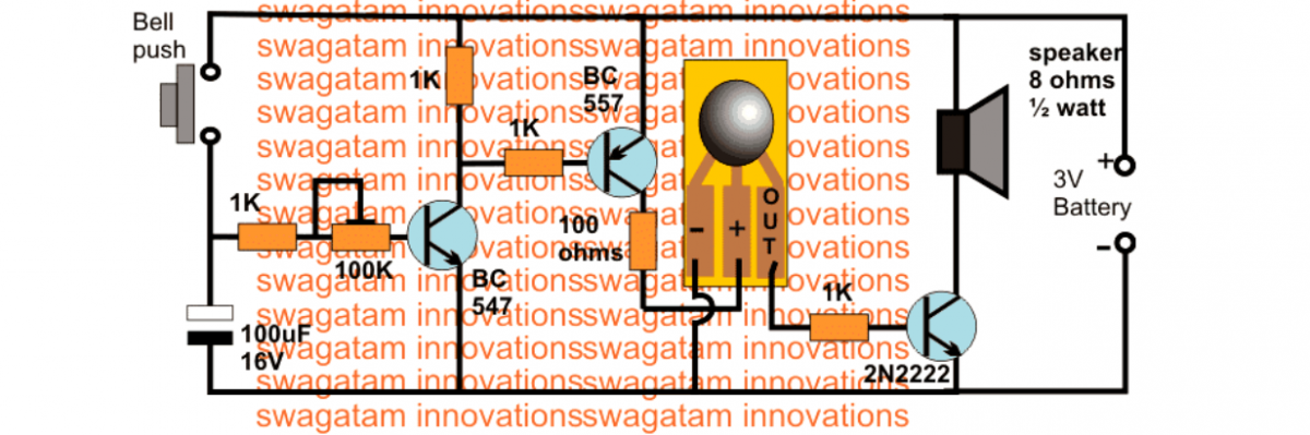
Using UM66
The following diagram shows how a UM66 IC musical tone generator can be used for door bell application
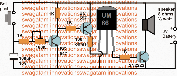
The diagram above depicts the proposed musical door bell circuit, the various stages may be understood with the following explanation.
The BC547 transistor along with the associated preset and the 100uF capacitor form a simple delay OFF timer circuit, where the preset and the capacitor determines the delay for which the sound output may be sustained once the indicated push button is pressed momentarily.
BC557 Function
The BC557 transistor functions like a switch and triggers ON/OFF in response to the conduction of the BC547 stage.
The collector of the BC557 can be seen linked with a COB which is the acronym for Chip On Board device, which is an embedded musical tune IC.
This IC is programmed internally to produce the specified tune as soon as a 3V potential is applied across its supply terminals.
The sound signal is acquired from the extreme right copper layout strip of the chip.
Since the output from the COB could be very low in current, it needs an amplification before the programmed sound can become loud and audible across a give area.
The third transistor 2N2222 is positioned to accept the weak sound signals from the COB and amplify it over the connected 8 ohm speaker.
Video Demonstration:
How COB (Chip on Board) Works
These COBs are plentifully available in the electronic spare part market today, and these come with a diverse range of different tunes such as Christmas melodies, birthday songs, new year tunes, congratulation wishing tune, animal sounds, and many other customized speech forms depending upon the users specifications.
In case you are unable to find these chips, a decent alternative could be in the form of the IC UM66 which are much popular and easily available in the market anywhere across the globe or could be also procured from any online electronic store.
The shown push button attached with the circuit is supposed to replace the home bell push button and may be extended to any distance, this will not affect the circuit performance.
When the push button is pressed, the BC547 switches ON and continues to conduct even after the switch is released due to the stored energy inside the 100uF capacitor.
The BC557 transistor responds to this and also switches ON supplying the required 3V potential to the attached COB, which now begins buzzing with the embedded piece of programmed tune.
The musical signal from the COB is forwarded to the next amplifier power transistor which instantly amplifies the music signals driving the connected speaker with a loud musical door bell sound.
The music continues only as long as the 100uF capacitor is able to sustain, and the music stops as soon as the 100uF is completely discharged.
The 100k preset may be set as per the user preference for enabling the desired length of the musical tune in response to every push of the bell button.
Door Buzzer Circuit
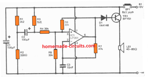
The above door buzzer circuit will produce a sharp buzzing sound whenever the push button is pressed by any guest at the door.
This design is suitable for users who do not wish to have a musical sound, instead prefer a buzzer kind of sound which sustains only as long as the button remain depressed.
The circuit is basically a square wave oscillator built around the op amp LM351. You can actually use any op amp instead of the specified one.
The parts C3, R7 decide the oscillation frequency which in turn produces the required buzzer door bell sound on the connected loudspeaker.
TR1 can be also replaced by any 1 amp NPN transistor if the specified number is not available.
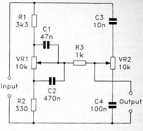
Door Bell Circuit Using UJT and IC 555
IC1 is configured as the tone generator, and this is a common 555 employed as a free-running multivibrator.
Capacitor C4 is charged up to 2/3 of the supply voltage through R5 and R6, and subsequently discharged down to roughly 1/3rd supply voltage through R6 and IC1.
This charge/discharge course of action keeps repeating non-stop. During this process the output pin 3 of ICI turns high as C4 charges, and turns low as it discharges.
The waveform generated at pin3 is used to operate a loudspeaker which as a result produces the door bell audio tone.
The 1/3rd supply voltage limit where C4 begins discharging is influenced externally by implementing a control voltage to pin 5 of IC 555 through a UJT oscillator circuit.
When this external UJT frequency at pin5 voltage increases, the charge and discharge periods of C4 are extended, creating a reduced working frequency.
As the UJT frequency at pin5 decreases, the charge and discharge periods of C4 likewise decreases, causing a higher operating frequency to be generated.
The door bell audio tone generated by the second frequency generator is as a result frequency modulated through a control voltage fed at pin#5 of IC1.
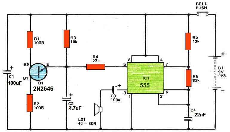
The warbling sound effect is generated by applying a control voltage which increases and decreases several times each second.
The nature of the output audio tone relies greatly on the waveform of the modulating signal from the UJT circuit, which is identical to a sawtooth signal.
This kind of waveform voltage goes up relatively slowly after which all of a sudden drops down to its lowest level.
This in fact provides a continuous decrease in output frequency accompanied by a fast resuming of the original high frequency even though this process happens very quickly to be distinctly recognized, allowing a pleasurable warbling effect to be heard on the speaker.
A unijunction relaxation oscillator is employed to build the modulating signal.
Capacitor C2 is charged by means of resistor R3 right up until a charge potential of approximately 7 V is reached, after which C2 starts discharging extremely fast by means of Q1 and R2.
Transistor Q1 subsequently shuts down, C2 begins to charge yet again, and so forth. R4 is used to connect the Q1 output with pin 5 of IC1.



Questions & Answers
sir ,I am senior citizens and retired, recently my home speaker doorbell short-circuit, it’s brand is Havells.
want to put new circuit in it.
I have no prior exposure to electronic.
please guide me.
thanks
b kapadia
Hello Bhupendra,
I understand your problem, however I have no idea what circuit the Havells door bell uses, so replacing it with an identical circuit may be difficult for me. I wish I could help you but without getting the schematic diagram of the same it may not be possible for me to proceed.
Please Sir I needed a Schematics for four bells with different sounds with four buttons to be used for School Quiz competition
Hi Lawal, can the sound of the bells be like a continuous buzzing tone?
Hello sir,
Abdulrooheem again, the 1k and 100k resistor how many watts are they and what other alter native can I use for UM66
Hello Usman, both the resistors are 1/4 watt 5% CFR
Hello sir ,
My name is Usman Abdulrooheem. I am currently working on this project and I have two questions, which are:
1) Is the um66 replacing the cob and
2) if I want to build a power supply instead of using a battery. How will I go about it.
Hello Usman,
1) Yes UM66 can be used to replace the COB.
2) You can use any 6V or 9V AC to DC adapter for powering the circuit
Thank you very much
Hello
Thank you for your very detailed explanation. From the explanation i deduce it’s like when the doorbell is pressed the capacitor is filled then the circuit works till it’s fully discharged. What in your opinion could be the cause of an intermittent non working doorbell? A dry joint or maybe failing capacitors or something else.
Thank you
Hello, yes that’s correct. The problem could be anything from dry joints, failing capacitor, or simply a faulty COB chip.
Hi Sir
I make Doorbell circuit with IC BT8031 – 2S , but i have prablem , when connecting power (6V) for one time circuite working and after this don’t work …. until unpluging power supply and repeat this for 10 min or longer …
please help me for solve this problem
Hi Mohammad, did you use a 1K resistor and 3V zener diode across the supply terminals of the IC?
yes
Check with 3V DC supply, if still the problem persists then your IC could be faulty.
Hi sir,
can you tell me about Audio COB (chip on board) that 1. How many types are there? 2. How the songs are programmed in this COB and if I want to do this at home then what all setup I need.
Thanking for giving us your valuable knowledge.
Hi Rakesh, there may be 100s of different COBs available in the market, but i have no idea how these are built or programmed…
Hallo dear Swagatam, swagatam.
I am a hobbyist, I collected a 12 tune musical bell cob kit from visa electronics, after assembly I found the ckt. is not working , I checked the tr.
bel- 187 but found ok. The bell is not working, could u pl. help ?
Thanking u
KC Panigrahy.
Hello dear KC Panigrahy, I remember I built the same circuit as yours, when I was in my school days, and I could make it successfully at the first attempt. These kits are actually very easy to build practically. However, in my case I had a 16 pin IC and not a COB, so if you have connected everything rightly yet it is not working then the COB could be the one which maybe faulty.
Alternatively you can also check the transistor pin orientation, you might have accidentally connected it wrongly
BEL187 is an obsolete transistor nowadays….you can try 8050 or 2N2222 instead and see if that works.
I have a Cona Musical electrical door bell. Recently it malfunctioned. So I just took it out and checked the ckt with multimeter but I cud find only two disc capacitors to be faulty ,so I just replaced it with new one of same value. but still my bell doesn’t function. Can u tell me what shud I check. Transistor 547 is ok , capacitor 16v, 10 mf is ok, resistors r ok , I dont know abt CoB , cud it be the problem? How to check CoB? Kindly suggest?
Is it a musical doorbell using COB or oscillator using transistors. If it is COB based you can try changing the COB with UM66 IC and check the response. Also check and confirm the power supply voltage if it’s through an adapter.
Hello
How can we connect this to normal mains (230 v) supply? Bells available in market can be directly connected to any normal ac outlet and gives music once switch is pressed.Even it can work in case of power failure using internal 3 volt battery.
Can you please modify circuit so that we can directly replace existing ac operated (ding dong) door bell with this?
hello, you can power the circuit through a small 3V adapter, or simply by using a spare mobile charger unit.
Sir,
I am a senior citizen,70 years old interested in electronic hobbiest.Regular reader of your article in electronics. I am having one Westminister Mantel Timepiece Clock (1.5 volt for running the time) given by my son in usa.Chiming in that is damaged. Running is good. Would you please suggest any alternate westminister chiming circuit diagram for that. It will be much thankful to do that.
Hello Savi, I am sorry I do not have the mentioned circuit with me at the moment, the ones which I have are rated to work on higher voltages so I cannot suggest you those.
Sir i need a water tank full alarm circuit. But the alarm must be musical means "please switch off the motor tank is full" but the language must be regional.
Sumit, you will have to get the chip programmed from a relevant source, I don't think ready made ICs are available with the mentioned speech clip.
thank you sir
Thankx..sir..for helping..me..
Can u provide me "link" for tda2003.
Google for "TDA2003 datasheet" you will find it inside the datasheet
Hello..sir..
Your previous project is awesome. I am regular reader of your site.
Now i hv "phillips dsp2800 home theater" .but its single speaker does not support or play with my laptop and mobile. So plz provilde any suitable "amplifier curcuit" to me…
And i hv lot of question regarding electronic curcuit.. Can i plz provide your email address..that can i regular touch with u??????
…you can expect much quicker response by commenting in this website…and you can feel free to comment as much as you want here.
Hello Saurabh,
you ca make a TDA2003 amp circuit and use it for amplifying your laptop music or any music source…
Hi sir,i'm Ezekiel from Nigeria and a student of electrical/electronic engineering. Sir I built your circuit ' simple musical door bell circuit ' it is working but the problem i'm facing now is that when the push button is press, the musical sound will play for the set time stop for like a second and continues for like another two seconds before finally shutting off.sir pls I need your help, what can I do to rectify this problem and thank you for this amazing circuit.God bless you.
Hi Ezekiel, adjust the 100K preset with some trial and error until the timing becomes just sufficient to play the tune only once.