• Skip to main content
  • Skip to primary sidebar

Homemade Circuit Projects

Need circuit help? Post them in the comments! I've answered over 50,000!

Blog | Categories | About | Hire Me | Contact | Calculators-online
You are here: Home / SMPS and Converters / SMPS Voltage Stabilizer Circuit

SMPS Voltage Stabilizer Circuit

Last Updated on July 5, 2025 by Swagatam 163 Comments

In this article I have explained a solid state switch-mode mains voltage stabilizer circuit without relays, using a ferrite core boost converter and a couple of half-bridge mosfet driver circuits. The idea was requested by Mr. McAnthony Bernard.

Table of Contents
  • Technical Specifications
    • The Design
    • Using the Shut Down Feature
    • Selecting the Frequency
    • Over Voltage Correction Circuit
    • Improving the above Design:
    • Circuit Operation
    • How to Set up the Circuit

Technical Specifications

Of late i started looking at voltage stabilizers use in house hold to regulate utility supply, boosting voltage when utility low and stepping down when utility is high.

It is built around mains transformer(iron core) wound in auto transformer style with many taps of 180v, 200v , 220v , 240v 260v etc..

the control circuit with the help of a relays selects the right tap for output. i guess you familiar with this device.

I started thinking to implement the function of this device with SMPS . Which will have the benefit of giving out constant 220vac and stable frequency of 50hz without using relays.

I have attach in this mail the block diagram of the concept.

Please let me know what you think, if it makes any sense going that route.

Will it really work and serve same purpose? .

Also i will need your help in the high voltage DC to DC converter section.

Regards
McAnthony Bernard

The Design

The proposed solid state ferrite core based mains voltage stabilizer circuit without relays may be understood by referring to the following diagram and the subsequent explanation.
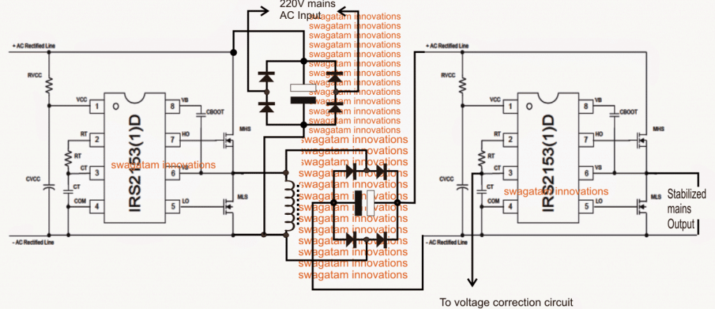
RVCC = 1K.1watt, CVCC = 0.1uF/400V, CBOOT = 1uF/400V

The figure above shows the actual configuration for implementing a stabilized 220V or 120V output regardless of the input fluctuations or an over load by using a couple of non-isolated boost converter processor stages.

Here two half bridge driver mosfet ICs become the crucial elements of the whole design. The ICs involved are the versatile IRS2153 which were designed specifically for driving mosfets in a half bridge mode without the need of complex external circuitry.

We can see two identical half bridge driver stages incorporated, where the left side driver is used as the boost driver stage while the right hand side is configured for processing the boost voltage into a 50Hz or 60Hz sine wave output in conjunction with an external voltage control circuit.

The ICs are internally programmed to produce a fixed 50% duty cycle across the output pinouts through a totem pole topology. These pinouts are connected with the power mosfets for implementing the intended conversions. The ICs are also featured with an internal oscillator for enabling the required frequency at the output, the rate of the frequency is determined by an externally connected Rt/Ct network.

Using the Shut Down Feature

The IC also features a shut down facility which can be used to stall the output in an event of an over current, over voltage or any sudden catastrophic situation.

For more info on this half bridge driver ICs, you may refer to this article: Half-Bridge Mosfet Driver IC IRS2153(1)D - Pinouts, Application Notes Explained

The outputs from these ICs are extremely balanced owing to a highly sophisticated internal bootstrapping and dead time processing which ensure a perfect and safe operation of the connected devices.

In the discussed SMPS mains voltage stabilizer circuit, the left side stage is used for generating around 400V from a 310V input derived by rectifying the mains 220V input.

For a 120V input, the stage may be set for generating around 200V through the shown inductor.

The inductor may be wound over any standard EE core/bobbin assembly using 3 parallel (bifilar) strands of 0.3mm super enameled copper wire, and approximately 400 turns.

Selecting the Frequency

The frequency should be set by correctly selecting the values of the Rt/Ct such that a high frequency of about 70kHz is achieved for the left boost converter stage, across the shown inductor.

The right hand side driver IC is positioned to work with the above 400V DC from the boost converter after appropriate rectification and filtration, as may be witnessed in the diagram.

Here the values of the Rt and Ct is selected for acquiring approximately 50Hz or 60Hz (as per the country specs) across the connected mosfets output

However, the output from the right side driver stage could be as high as 550V, and this needs to be regulated to the desired safe levels, at around 220V or 120V

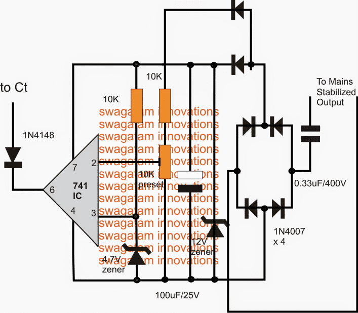
For this a simple opamp error amplifier configuration is included, as depicted in the following diagram.
Over Voltage Correction Circuit

As shown in the above diagram, the voltage correction stage utilizes a simple opamp comparator for the detection of the over voltage condition.

The circuit needs to be set only once in order to enjoy a permanent stabilized voltage at the set level regardless of the input fluctuations or an overload, however these may not be exceeded beyond a specified tolerable limit of the design.

As illustrated the supply to the error amp is derived from the output after appropriate rectification of the AC into a clean low current stabilized 12V DC for the circuit.

pin#2 is designated as the sensor input for the IC while the non-inverting pin#3 is referenced to a fixed 4.7V through a clamping zener diode network.

The sensing input is extracted from an unstabilized point in the circuit, and the output of the IC is hooked up with the Ct pin of the right side driver IC.

This pin functions as the shut down pin for the IC and as soon as it experiences a low below 1/6th of its Vcc, it instantly blanks out the output feeds to the mosfets shutting down the proceedings to a stand still.

The preset associated with pin#2 of the opamp is appropriately adjusted such that the output mains AC settles down to 220V from the available 450V or 500V output, or to 120V from a 250V output.

As long as the pin#2 experiences a higher voltage with reference to pin#3, it continues to keep its output low which in turn commands the driver IC to shut down, however the "shutting down" instantly corrects the opamp input, forcing it to withdraw its output low signal, and the cycle keeps self correcting the output to the precise levels, as determined by the pin#2 preset setting.

The error amp circuit keeps stabilizing this output and since the circuit has the advantage of a significant 100% margin between the input source volatge and the regulated voltage values, even under extremely low voltage conditions the outputs manages to provide the fixed stabilized voltage to the load regardless of the voltage, the same becomes true in a case when an unmatched load or an overload is connected at the output.

Improving the above Design:

A careful investigation shows that the above design can be modified and improved greatly to increase its efficiency and output quality:

  1. The inductor is actually not required and can be removed
  2. The output must be upgraded to a full bridge circuit so that the power is optimal for the load
  3. The output must be a pure sinewave and not a modified one as may be expected in the above design

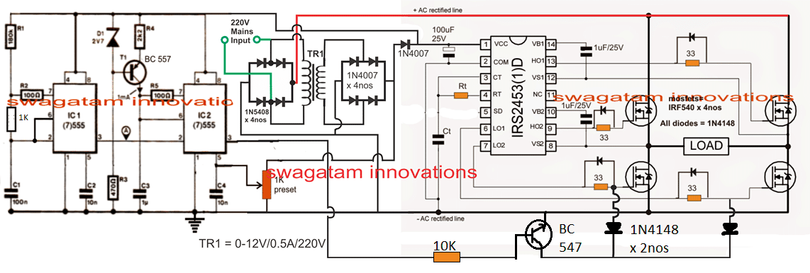
All these feature have been considered and taken care of in the following upgraded version of the solid state stabilizer circuit:
Circuit Operation

  1. IC1 works like a normal astable multivibrator oscillator circuit, whose frequency can be adjusted by changing the value of R1 appropriately. This decides the number of "pillars" or "chopping" for the SPWM output.
  2. The frequency from IC 1 at its pin#3 is fed to to pin#2 of IC2 which is wired as a PWM generator.
  3. This frequency is converted into triangle waves at pin#6 of IC2, which is compared by a sample voltage at pin#5 of IC2
  4. Pin#5 of IC2 is applied with sample sinewave at 100 Hz frequency acquired from the bridge rectifier, after appropriately stepping down the mains to 12V.
  5. These sinewave samples are compared with the pin#7 triangle waves of IC2, which results in a proportionately dimesnioned SPWM at pin#3 of IC2.
  6. Now, the pulse width of this SPWM depends on the amplitude of the sample sinewaves from the bridge rectifier. In other words when the AC mains voltage is higher produces wider SPWMs and when the AC mains voltage is lower, it reduces the SPWM width and makes it narrower proportionately.
  7. The above SPWM in inverted by a BC547 transistor, and applied to the gates of the low side mosfets of a full bridge driver network.
  8. This implies that when the AC mains level will drop the response on the mosfet gates will be in the form of proportionately wider  SPWMs, and when the AC mains voltage increases the gates will experience a proportionately deteriorating SPWM.
  9. The above application will result in a proportionate voltage boost across the load connected between the H-bridge network whenever input AC mains drops, and conversely the load will go through a proportionate amount voltage drop if the AC tends to rise above the danger level.

How to Set up the Circuit

Determine the approximate center transition point where the SPWM response may be just identical to mains AC level.

Suppose you select it to be at 220V, then adjust the 1K preset such that the load connected to the H-bridge receives approximately 220V.

That's all, the set up is complete now, and the rest will be taken care of automatically.

Alternatively, you can fix the above setting towards the lower voltage threshold level in the same manner.

Suppose the lower threshold is 170V, in that case feed a 170V to the circuit and adjust the 1K preset until you find approximately 210V across the load or between the H-bridge arms.

These steps concludes the setting up procedure, and the rest will automatically adjust as per the input AC level alterations.

Important: Please connect a high value capacitor in the order of 500uF/400V across the AC rectified line fed to the H-bridge network, so that the rectified DC is able to reach upto 310V DC across the H-bridge BUS lines.

You'll also like:

  • boostHow to Build a Boost Converter Circuit: Explained with Calculations
  • 12v2B52Bamp2Btransformerless2Bbattery2Bcharger2Bcircuit12V, 5 Amp SMPS Battery Charger Circuit
  • DC to DC converter12 V to 30 V High Current Boost Converter Circuit [Variable]
  • XL6009 DC-DC Converter IC: Pinout, Working, Circuit Diagram, and Applications

Filed Under: SMPS and Converters Tagged With: SMPS, Stabilizer, Voltage

About Swagatam

I am an electronics engineer and doing practical hands-on work from more than 15 years now. Building real circuits, testing them and also making PCB layouts by myself. I really love doing all these things like inventing something new, designing electronics and also helping other people like hobby guys who want to make their own cool circuits at home.

And that is the main reason why I started this website homemade-circuits.com, to share different types of circuit ideas..

If you are having any kind of doubt or question related to circuits then just write down your question in the comment box below, I am like always checking, so I guarantee I will reply you for sure!


Previous Post: « Adjustable CDI Spark Advance/Retard Circuit
Next Post: Simple Musical Door Bell Circuit »

Reader Interactions

Questions & Answers

Total Posts: 163
Newest Oldest
David
February 6, 2026 • 7 months ago #200495

SIR. IRF540 IS A 100V MOSFET TRANSISTOR! ARE YOU SHURE?

Reply
SwagatamAdmin
February 6, 2026 • 7 months ago #200514

Hi David, yes, I checked it again, as per the datasheet the VDS max voltage of IRF540 is 100V DC

Reply
Julius Lyonga Luma Breeze
October 28, 2025 • 10 months ago #189283

sir i want to ask ,is the final output going to be a square wave or sine?

Reply
SwagatamAdmin
October 28, 2025 • 10 months ago #189289

Julius, the output is a DC which needs to be converted to AC further…I think the first design has some problems…

Reply
Julius Lyonga Luma Breeze
October 28, 2025 • 10 months ago #189316

ok sir please i know this might not be about the same topic but ,i have been trying to use a pic microcontroller to make a sine wave inverter an i have been using proteus but seems the transformers there are not high frequency one so all my efforts to get a sine wave at the out put is always with high harmonics, please do you know anything i could do ?

Reply
SwagatamAdmin
October 29, 2025 • 10 months ago #189351

Julius, you can try adding an LC filter at the output AC side of the inverter, by calculating the components as per the following article:
https://www.homemade-circuits.com/inverter-lc-filter-calculator/

Reply
Ovidiu Popa
February 8, 2022 • 5 years ago #111974

Hi.
I want to try to make one power supply 3x200Vac 300Hz (for FEIN electric tools 2100 W )from main (1 phase 230Vac ) .
I`ve try to find similar schematic but no results.
Can you help me please with this kind of schematic?
Thank you very much.
Ovidiu`s

Reply
SwagatamAdmin
February 8, 2022 • 5 years ago #111975

Hi, To generate 600 V from from 220V you will need a boost converter circuit. However, unfortunately I do not have a schematic for this, at the moment.

Another good option is to get a 220V to 600V made-to-order transformer.

Reply
Ovidiu's
February 8, 2022 • 5 years ago #111980

HFS17-300 îs power supply front Fein.
Input 230 Vac , output three phases 200 Vac 300Hz

Reply
SwagatamAdmin
February 9, 2022 • 5 years ago #112022

Sorry, I don’t have a proper schematic for this.

Reply
Olusegun
October 3, 2021 • 5 years ago #99554

Hello Swag,

I thank you a million times for your contribution.
Please in my country there is no IRS2453. What are other possible replacements for it in the last diagram.

Reply
SwagatamAdmin
October 3, 2021 • 5 years ago #99596

Thank you Olesegun, IRS2453 is the most standard 3 phase driver IC, if it is not available to you, then other variants maybe also not available in your area. You can try searching for “full bridge driver IC” online, you may probably find some other suitable options.

Reply
Brian Baumann
March 25, 2021 • 5 years ago #87952

Thank you for sharing all of your knowledge! I would like to ask about the mains SMPS voltage stabilizer circuit. I am looking to stabilize 120VAC in a mobile rig for some voltage sensitive entertainment gear. Over voltage is not a concern, but voltage sags are and always seem to be a problem. I need an output that stays solid at 112VAC – 120VAC when the input is fluctuating. Is this circuit what I would want?

Reply
SwagatamAdmin
March 25, 2021 • 5 years ago #87975

You can try implementing the last design, however it is not a tested design so I may not be able to guarantee the results.

Reply
Godfrey
March 6, 2021 • 5 years ago #87586

Hello Mr Swags!
You’re doing a great work there. Please can you help direct me on the components to use in order to obtain a 4kw and 2kw transformerless voltage stabilizer. I would also like to get a clear circuit on it
Thanks

Reply
SwagatamAdmin
March 6, 2021 • 5 years ago #87597

Hello Godfrey,

Please build a smaller version of the design successfully and confirm it, if it works for you nicely, then you can upgrade it to any level

Reply
Job Thykkoottathil
January 10, 2021 • 6 years ago #86017

Dear Mr. Swagatam,
Referring to the first circuit diagram, Is it possible that you can explain:
1) How the right side bridge gets AC supply so that the right half of the circuit gets rectified DC? Can you please mark the circuit with a circuit path for both positive and negative half cycles?

2) Assuming that the right side somehow gets supplied with 310 VDC, how it will be converted to AC? Please explain the logic.

Thanks and kind regards,

Job Thykkoottathil.

Reply
SwagatamAdmin
January 10, 2021 • 6 years ago #86040

Dear Mr. Job, the first circuit uses a half wave bridge, so the AC will not have negative AC cycles, rather a square wave stabilized output.
The inductor is used for stepping up the 310V to 400V or higher, at which a 220V output is achieved on the right IC 2153 IC output, in normal conditions

The circuits explained at the bottom of the article are designed to produce full wave sine wave equivalent output.

Reply
Job Thykkoottathil
December 24, 2020 • 6 years ago #85594

Dear Mr. Swagatam,
In the third circuit above, I noticed that a smoothing capacitor at the high voltage bus bar is missing. Is it left out intentionally?
Suppose the line voltage dropped to 200 V in which case, the peak will be 282.8. Without a storage (Smoothing) capacitor, will the circuit be able to provide 220 V in a loaded, say 1000 W, condition?
King regards,
Job Thykkoottathil.

Reply
SwagatamAdmin
December 24, 2020 • 6 years ago #85597

…..the wattage handling capacity will depend on the value of the capacitor and the wattage of the MOSFETs.

Reply
job Thykkoottathil
December 25, 2020 • 6 years ago #85605

Thank you Mr. Swagatam;
I happened to think that this capacitor was needed in the first circuit only.
Wishing you greetings of the season and a safe and prosperous New Year, and with
Kind regards,
Job Thykkoottathil.

Reply
SwagatamAdmin
December 26, 2020 • 6 years ago #85616

You are welcome Mr.Job, I appreciate your feedback, and wish you too a Merry Christmas and Happy 2021

Reply
SwagatamAdmin
December 24, 2020 • 6 years ago #85596

Dear Mr. Job, the capacitor is necessary, there’s a message at the end of the article, put exactly to notify this issue!

Reply
Job Thykkoottathil
December 23, 2020 • 6 years ago #85576

“Suppose you select it to be at 220V, then adjust the 1K preset such that the load connected to the H-bridge receives approximately 220V.”
“Suppose the lower threshold is 170V, in that case feed a 170V to the circuit and adjust the 1K preset until you find approximately 210V across the load or between the H-bridge arms.”
In order to obtain 220 V, you input 220 and adjust 1K to read 220 at the load. But for the lower threshold, you you input 170 V and adjusted the pot to obtain 210 V ; not 170 V. Please explain.

Thanks and regards,
Job Thykkoottathil

Reply
Job
December 22, 2020 • 6 years ago #85535

Hi,
What are the values of Rt & Ct?

Reply
SwagatamAdmin
December 22, 2020 • 6 years ago #85542

it will need to be determined with experimentation.

Reply
Daud Yusuf
September 22, 2020 • 6 years ago #82469

I have a plan to built a small micro(or pico) hydro electric with permanent magnet generator, can i implement this schematic for such task (as AVR) ?
Thanks a lot !

Reply
SwagatamAdmin
September 22, 2020 • 6 years ago #82480

If you have understood the concept well and confident about the working, then you can go ahead.

Reply
Daud Yusuf
September 23, 2020 • 6 years ago #82490

As you say, Go Ahead !
Bahut Bahut Shukriya, Swagatam Ji !

Reply
jyotirmoy niyogi
July 26, 2020 • 6 years ago #80762

Can you please tell me what would be the value of the storage capacitor on the rectified AC bus for 2 kva application. Any thumb rule ?

Reply
SwagatamAdmin
July 26, 2020 • 6 years ago #80767

There;s a rule of thumb for selecting filter capacitor but I don’t remember it, however you can easily calculate it with the formula given in the following article:

https://www.homemade-circuits.com/calculating-filter-capacitor-for/

Reply
Muhammad Waqar Shakoor
June 11, 2020 • 6 years ago #79369

Hello,
Can you provide High Resolution Circuit Diagram of above circuit?

Please provide link to high resolution Image of improved version of this design.

Thanks

Reply
SwagatamAdmin
June 11, 2020 • 6 years ago #79393

Hi, if your having difficulty seeing the details of the IRS2153 in the first diagram, you can refer to the following datasheet:

https://www.infineon.com/dgdl/Infineon-IRS2153D-DataSheet-v01_00-EN.pdf?fileId=5546d46269e1c019016a4ea5480f0d88

Reply
rajiv
January 19, 2020 • 7 years ago #75072

Hi Swagatham, what would be the maximum watts of the load with the given components of the improved version of stablizer schematic? thank you.

Reply
SwagatamAdmin
January 20, 2020 • 7 years ago #75120

Hi Rajiv, the MOSFETs are incorrectly shown a IRF540, which is not rated at 310V, so please change it to IRF740 which will handle about 2000 watts

Reply
Irshad Ali
September 21, 2019 • 7 years ago #70372

Sir i want to make a project. 4 kva stabilizer pwm base without transformer and relays please help me sir

Reply
SwagatamAdmin
September 21, 2019 • 7 years ago #70374

Irshad, concept is discussed here, but is very difficult:

https://www.homemade-circuits.com/transformerless-pwm-mains-voltage/

Reply
Ragess
June 18, 2019 • 7 years ago #67745

Dear Swagatam, how are you?

I come to your website to dip into so many cool circuit description and explanation. Just great.
Few questions I have, not sure if they relate to you or not.

1. Can I use 12v ferite transformer from SMPS rewind to 24v turns on secondary and use it as linear step down iron core transformer to run 24v 300W DC motor directly after rectification.

2. If it is possible to rewind 12v secondary to 24v on 500W ATX ferite transformer, so that I get 24V 500W from the yellow wire, along with 5V and 12v. If it is possible to change just ferite transformer to get above mentioned ratings. Thanks

Reply
SwagatamAdmin
June 18, 2019 • 7 years ago #67746

Thank you Ragess, yes that’s certainly feasible, I have tried that myself successfully. However increasing the voltage might result in decreasing the current and the wattage proportionately.

Reply
Ragess
June 26, 2019 • 7 years ago #67946

Hi Swagatam.
Can you be reached with [email protected] or just here at the webpage site?
Can I mail you at this email address or any other if available?

Reply
SwagatamAdmin
June 27, 2019 • 7 years ago #67954

Hi Ragess, I prefer discussing through comments because I can answer them quickly. I check emails may be only once a day, but I stay on web pages most of time, so you can get quick replies here!

Reply
candra
August 17, 2018 • 8 years ago #62492

dear swag,
do you have PCB layout from that circuit?
it’s complicated for me to make it, i want to build one for my computer

thanks.

Reply
SwagatamAdmin
August 18, 2018 • 8 years ago #62508

I ams orry Candra, I do not have a PCB layout for this design at the moment. But PCB should be designed only once the design is conformed over a veroboard and after everything is finalized

Reply
Ernset Kwesi Smith
February 20, 2018 • 9 years ago #58618

pls am looking for
4000 watts smps full bridge

Reply
lins
February 11, 2018 • 9 years ago #58353

hello sir ,
can i use the above circuit to stabilise a motor of 600watts

Reply
SwagatamAdmin
February 11, 2018 • 9 years ago #58360

hello lins,

it can handle any form of load, as long as the the bridge capacitors are adequately rated as per the load specifications….

Reply
lins
February 11, 2018 • 9 years ago #58363

thanks for the reply…
you’ re awesome…
i will recomend your website to everyone..

Reply
SwagatamAdmin
February 11, 2018 • 9 years ago #58365

You are most welcome Lins!!

Reply
Ashor
January 28, 2018 • 9 years ago #58035

Hello Swagatam.
Thank you for your good job. Kindly explain how to modify this circuit to work for :
Minimum Input Voltage ~70V
Maximum Input Voltage ~400V
OUTPUT = 220V Constant
Thanks.

Reply
SwagatamAdmin
January 28, 2018 • 9 years ago #58046

Thanks Ashor, the adjustments can be customized using the 1K preset for any desired specifications, however since a transformer is not used, the bridge rectification will involve large capacitors in the order of many 1000s of microfarads.

Reply
Muhsammad Waqas
November 25, 2017 • 9 years ago #56102

Hi swagatam can u design a 2kva transformerless pure sine wave voltage stabilizer circuit (input 150-300v 50Hz ) having output of 230v 50Hz.
My main concern is stabilized 230v 50Hz having pure sine wave output. The waveform and voltages should be stable at no load and at full load. I will pay for it.

Reply
SwagatamAdmin
November 25, 2017 • 9 years ago #56104

Hi Muhammad, I think the design presented in the above article can be improved and modified differently to achieve the required results. The shown inductor is actually not required….we can simply do it through a full-bridge driver and an IC 555 PWM Controller. since we already have 310V as the input which is much higher than 220V we can use this margin for stabilizing the output within a wide range.

I’ll try to update the new design soon.

Reply
Muhammad Waqas
December 8, 2017 • 9 years ago #56501

swatam please suggest a pwm generator circuit which is synchronized with ac input (5v or 12v, source frequency) compared with ic built in triangular waves.

Reply
SwagatamAdmin
December 8, 2017 • 9 years ago #56503

Hi Muhammad, I have already provided it to you in the auto-stabilizer idea, the two ICs IC1/IC2 using IC 555 are in sync with the AC 12V feed at its pin#5 for generating the SPWMs

Reply
Muhammad Waqas
November 28, 2017 • 9 years ago #56189

ok i will make the circuit after your explanation

Reply
SwagatamAdmin
November 29, 2017 • 9 years ago #56197

I have updated the circuit description, you can check it out at the bottom of the article….

Reply
Muhammad Waqas
December 1, 2017 • 9 years ago #56284

thanks swagatam i will make the circuit

Reply
SwagatamAdmin
December 1, 2017 • 9 years ago #56286

OK thanks!!

Reply
Muhammad Waqas
November 30, 2017 • 9 years ago #56248

Swagatm my main concern is to maintain exact 220v across the full load of 2 kva in case of low volatge (170V)

Reply
SwagatamAdmin
November 30, 2017 • 9 years ago #56250

Hi Muhammad, The IC2 is synchronized with the AC phase so the output will be constant with nominal load, but the voltage may drop with increase in load, to compensate this we’ll require high value capacitors across the rectified AC line, as I mentioned in my earlier comment.

Reply
Muhammad Waqas
November 30, 2017 • 9 years ago #56246

Hi swagatam the circuit seems quite well in case of high voltages but in case of low voltage (170V) how will it boost the voltages to 220 and will maintain the voltages at full load (2Kva).

Reply
SwagatamAdmin
November 30, 2017 • 9 years ago #56247

The peak value of 170V will be 210V, so if you adjust the PWM at full range at 170V, you will get around 200V at the output at 170V input.

for 2kva operation you may require huge capacitors across the full-bridge bus line….a couple of 10,000uF/400V caps may be required

Reply
Muhammad Waqas
November 29, 2017 • 9 years ago #56219

thank u so much sir

Reply
SwagatamAdmin
November 29, 2017 • 9 years ago #56220

you are welcome!!

Reply
Muhammad Waqas
November 25, 2017 • 9 years ago #56105

thank u so much swagatam i will wait for your design…how much time u will take approximately? I can pay u if u design urgent and according to my requirements

Reply
SwagatamAdmin
November 26, 2017 • 9 years ago #56110

You are welcome Muhammad, I’ll try to update it in two days. It will be free of cost

Reply
Muhammad Waqas
December 7, 2017 • 9 years ago #56477

swagatm i want to simulate some circuit if irs2453 on software plz tell me any software where it can be simulated…mostly simulators don’t contains irs2453 ic.

Reply
SwagatamAdmin
December 8, 2017 • 9 years ago #56487

Muhammad, I have no idea about it because for me simulating softwares are not so useful, in fact they will most of the time produce misleading results, and by the way there’s nothing to be simulated in the full bridge circuit it’s just an IC and 4 mosfets which will work without fail.

Reply
Muhammad Waqas
December 3, 2017 • 9 years ago #56334

one thing which is not clear in my mind is output frequency and switching frequency, is these two are same? can we perform switching on high frequency by keeping the output frequency of 50 Hz, if yes than how we will obtain high frequency and how we will set output frequency? rt and ct will determine output frequency or switching frequency plz explain this thing.

Reply
SwagatamAdmin
December 3, 2017 • 9 years ago #56343

Muhammad, the switching frequency is 50Hz which is created by the Rt/Ct values, the other frequency generated by the IC 555s is to chop this 50Hz into SPWM format, as shown in the previous linked diagram.

Reply
SwagatamAdmin
December 3, 2017 • 9 years ago #56344

the output frequency will be 50Hz, and each of these 50 Hz cycles will have 1400 Hz chopping

Reply
Muhammad Waqas
December 2, 2017 • 9 years ago #56318

swagatam what will be output frequency of the stabilizer if chopping frequency is 1400 Hz?

Reply
SwagatamAdmin
December 2, 2017 • 9 years ago #56321

after proper filtration it will be 50 Hz, or at the frequency determined by RT/Ct

Reply
Muhammad Waqas
December 2, 2017 • 9 years ago #56305

ok thank u so much swagatam

Reply
SwagatamAdmin
December 2, 2017 • 9 years ago #56308

you are welcome!!

Reply
Muhammad Waqas
December 1, 2017 • 9 years ago #56295

ok plz provide the formula for selecting rt and ct and what type of filter will be needed at the output plz design that filter for me

Reply
SwagatamAdmin
December 2, 2017 • 9 years ago #56303

formula can be found on this page

https://www.homemade-circuits.com/simplest-full-bridge-inverter-circuit/

filter I am not sure how to design, you will have figure it out yourself

Reply
Muhammad Waqas
December 1, 2017 • 9 years ago #56290

sawagtam what should be the chopping frequency and how we can calculate it and what is the effect of chopping frequency on output frequency

Reply
SwagatamAdmin
December 1, 2017 • 9 years ago #56292

Hi Muhammad, the the following example diagram we can see 14 blocks on each cycle,

f1

each 1/2 cycle in 50 Hz is of 10ms length, so in 10ms we can see 14 blocks….so in 1 second it will be 1sec/10ms = 100

and 100 x 14 = 1400 blocks

so you can try 1400Hz and see the results

Reply
SwagatamAdmin
December 1, 2017 • 9 years ago #56293

chopping effect will convert the output into pure sinewave but will also create harmonics which will need to be cancelled with proper filter circuits at the output

Reply
Muhammad Waqas
November 28, 2017 • 9 years ago #56176

thanks swagatam i will make the circuit on breadboard after your explanation and then i will make a pcb of this circuit.

Reply
SwagatamAdmin
November 28, 2017 • 9 years ago #56187

sure Muhammad, but please make sure that you first understand all the stages perfectly and then simulate it in your mind to get a clear picture of the idea and only after that go for the practical attempt

Reply
Muhammad Waqas
November 28, 2017 • 9 years ago #56170

thank u so much swagatam for your efforts, i will wait for the circuit details…can u suggest any software where i can simulate this circuit??

Reply
SwagatamAdmin
November 28, 2017 • 9 years ago #56175

You are welcome Muhammad, I’ll try to update the explanation soon, a simulator will not be able to be simulate the circuit because the circuit is quite complex, I have seen simulators failing to simulate even simpler circuits correctly.

Understanding and simulating in mind is the only perfect way of judging a circuit design.

Reply
SwagatamAdmin
November 28, 2017 • 9 years ago #56168

Muhammad, I have the updated the diagram….but it’s without explanation I’ll update the explanation as soon as I am free..

Reply
Muhammad Waqas
November 27, 2017 • 9 years ago #56134

thanks swagatam i will wait for your design

Reply
SwagatamAdmin
November 27, 2017 • 9 years ago #56143

I am working on it, thanks!

Reply
Muhammad Waqas
November 26, 2017 • 9 years ago #56113

thanks swagatam please keep in mind pure sine wave and when voltage will low (150V ac) then we will get approximately 210V dc instead of 310v plz consider this thing because voltages are mostly low there is 20% chance of high voltages.

Reply
SwagatamAdmin
November 26, 2017 • 9 years ago #56118

yes, I have noted the specs!

Reply
Athri H D
November 19, 2017 • 9 years ago #55951

Thank you. But what I am asking is isn’t it possible to amplify without iron ore transformer? Using MOSFET bridge

Reply
SwagatamAdmin
November 19, 2017 • 9 years ago #55952

Transformer will not be required because the input does not require any amplification but a circuit will be required for converting DC into sinewave, in the above links you can eliminate the transformer, and attach the load directly across the mosfet output

here’s another example

https://www.homemade-circuits.com/solar-inverter-circuit-for-15-ton-ac/

Reply
View Older Comments

Need Help? Please Leave a Comment! We value your input—Kindly keep it relevant to the above topic! Cancel reply

Your email address will not be published. Required fields are marked *

Primary Sidebar


Categories

  • Arduino Projects (95)
  • Audio and Amplifier Projects (134)
  • Automation Projects (18)
  • Automobile Electronics (104)
  • Battery Charger Circuits (90)
  • Datasheets and Components (109)
  • Electronics Theory (150)
  • Energy from Magnets and Earth (41)
  • Games and Sports Projects (11)
  • Grid and 3-Phase (20)
  • Health related Projects (27)
  • Home Electrical Circuits (13)
  • Indicator Circuits (16)
  • Inverter Circuits (100)
  • Lamps and Lights (163)
  • Meters and Testers (72)
  • Mini Projects (28)
  • Motor Controller (68)
  • Oscillator Circuits (30)
  • Pets and Pests (15)
  • Power Supply Circuits (91)
  • Remote Control Circuits (50)
  • Security and Alarm (65)
  • Sensors and Detectors (107)
  • SMPS and Converters (46)
  • Solar Controller Circuits (62)
  • Temperature Controllers (44)
  • Timer and Delay Relay (50)
  • Voltage Control and Protection (44)
  • Water Controller (37)
  • Wireless Circuits (31)


Circuit Simulator

circuit simulator image


Subscribe to get New Circuits in your Email


Other Links

  • Privacy Policy
  • Cookie Policy
  • Disclaimer
  • Copyright
  • Videos
  • Sitemap

People also Search

555 Circuits | 741 Circuits | LM324 Circuits | LM338 Circuits | 4017 Circuits | Ultrasonic Projects | SMPS Projects | Christmas Projects | MOSFETs | Radio Circuits | Laser Circuits | PIR Projects |


Recent Comments

  • Swagatam on Electronic Circuit Projects, Tutorials, and Practical Engineering Solutions
  • Swagatam on Electronic Circuit Projects, Tutorials, and Practical Engineering Solutions
  • Swagatam on 4 Simple Battery Desulfator Circuits Explored
  • Swagatam on 4 Simple Battery Desulfator Circuits Explored
  • Swagatam on PIR Controlled Solar Garden Light Circuit

Social Profiles

  • Twitter
  • YouTube
  • Instagram
  • Pinterest
  • My Facebook-Page
  • Stack Exchange
  • Linkedin

© 2026 · Swagatam Innovations