• Skip to main content
  • Skip to primary sidebar

Homemade Circuit Projects

Need circuit help? Post them in the comments! I've answered over 50,000!

Blog | Categories | About | Hire Me | Contact | Calculators-online
You are here: Home / Audio and Amplifier Projects / Ding Dong Bell Circuit that Saves Electricity

Ding Dong Bell Circuit that Saves Electricity

Last Updated on May 15, 2026 by Swagatam Leave a Comment

This circuit goes beyond being a simple two-tone doorbell. Instead, it utilizes envelope modulation to produce an authentic 'ding-dong' chime sound.

Table of Contents
  • Circuit Diagram
  • How the Circuit Works
    • Parts List
  • Ding Dong Bell Circuit using Two IC 555
    • Parts List

Additionally, it incorporates a power-saving feature, consuming zero power in standby mode.

Circuit Diagram
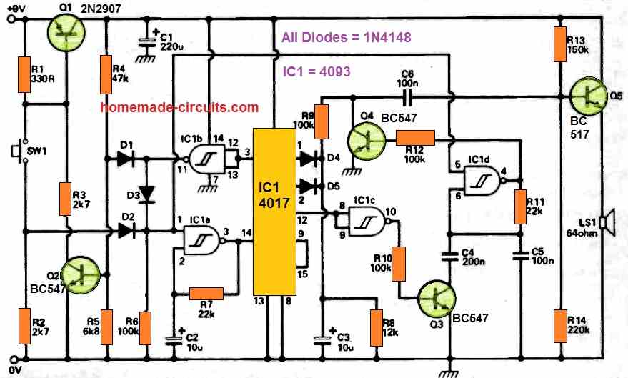
ding dong bell circuit schematic
The IC 4017 is mistakenly shown as IC1, it should be IC2

How the Circuit Works

When SW1 is pressed, it triggers Q1 to power the remaining circuitry.

IC1a serves as a low-frequency oscillator, generating clock pulses for the decade counter IC2.

Q2 activates when the counter reaches zero, sustaining power for a complete cycle.

The envelope, characterized by rapid attack and gradual decay, is shaped by D4, C3, and R8 during the initial count.

Q4 modulates the output of the audio oscillator IC1d, which then feeds into amplifier Q5 and the loudspeaker. When the counter reaches count 5, a new envelope begins using D5, C3, and R8.

Simultaneously, the carry-out pin goes low, introducing C4 in parallel with C5 to produce the deeper 'dong' sound.

Upon reaching count 9, the counter is reset, and Q1 and Q2 are deactivated through IC1b, making the circuit ready for another ringing cycle.

Parts List

  • All Resistors are 1/4 watt 5% CFR
  • R1 = 330 Ohms
  • R2, R3 = 2.7 K
  • R4 = 47 K
  • R5 = 6.8 K
  • R6, R9, R10, R12 = 100 K
  • R7, R11 = 22 K
  • R8 = 12 K
  • R13 = 150 K
  • R14 = 220 K
  • Capacitors
  • C1 = 220 uF / 25 V Electrolytic
  • C2, C3 = 10 uF / 25 V Electrolytic
  • C4 = 200 nF Ceramic
  • C5, C6 = 100 nF Ceramic
  • Semiconductors
  • Q1 = 2N2907
  • Q2, Q3, Q4 = BC547
  • Q5 = BC517
  • IC1a, b, c, d = Gates from IC 4093
  • IC2 = 4017
  • SW1 = push button
  • LS1 = 64 ohm Loudspeaker

Ding Dong Bell Circuit using Two IC 555
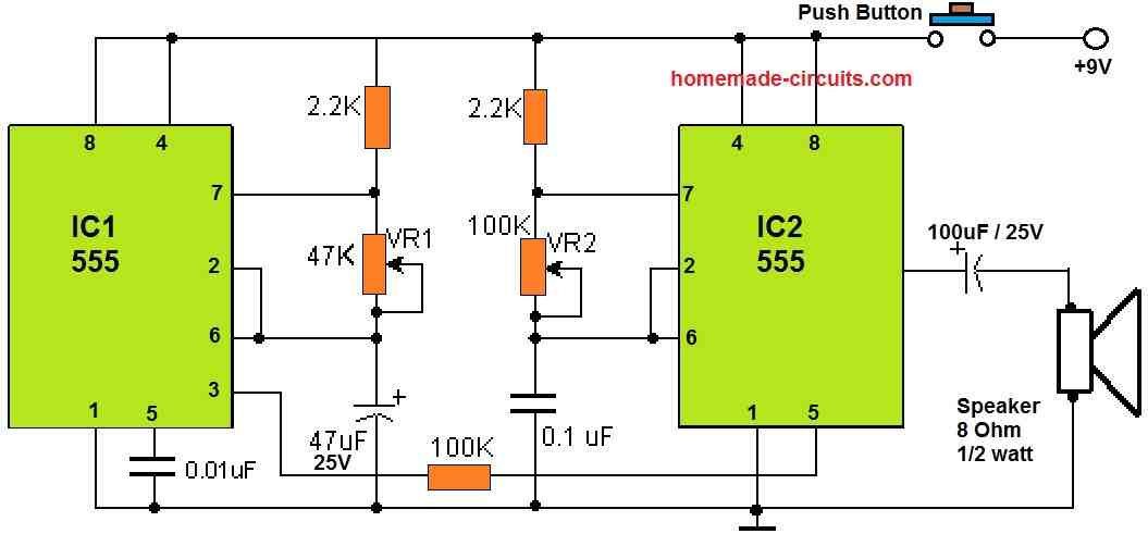
This circuit generates the iconic chime of the Big Ben clock. When activated, it emits the characteristic "ding dong" sound.

Fundamentally, the circuit switches back and forth between two frequencies, which can be customized. This action results in the formation of the "ding-dong" sound.

The initial integrated circuit (IC1) generates oscillations at approximately 1Hz. The subsequent integrated circuit (IC2) is influenced by the fluctuating voltage from the first IC, which modulates the tone.

The speed of the transition between the two frequencies is governed by IC1, determining the switching pace. On the other hand, IC2 influences the quality of the sound produced in the end.

By manipulating potentiometer VR1, the rate of frequency alternation can be fine-tuned, and by adjusting potentiometer VR2, the pitch of the sound can be modified.

Parts List

  • Resistors are 1/4 watt 5% CFR
  • 2.2 K = 2nos
  • 100 K = 1no
  • 47 K preset = 1no
  • 100 K preset = 1no
  • Capacitors
  • 0.01 uF Ceramic = 1no
  • 0.1 uF Creamic = 1no
  • 100 uF / 25V = 1 no
  • Semiconductors
  • IC 555 = 2nos
  • Loudspeaker 8 ohms 1/2 watt = 1no
  • Battery 9 V = 1no
  • Push button Switch = 1no

You'll also like:

  • cartridge5 Simple Audio Mixer Circuits Explained
  • PCB DesignMake this DIY Contact MIC Circuit
  • 7809 IC regulated power supply circuitTrain Sound Simulator Circuit
  • crystalMake this Crystal Radio Set Circuit using No Batteries

Filed Under: Audio and Amplifier Projects Tagged With: Bell, Ding, Dong, Electricity, Saves

About Swagatam

I am an electronics engineer and doing practical hands-on work from more than 15 years now. Building real circuits, testing them and also making PCB layouts by myself. I really love doing all these things like inventing something new, designing electronics and also helping other people like hobby guys who want to make their own cool circuits at home.

And that is the main reason why I started this website homemade-circuits.com, to share different types of circuit ideas..

If you are having any kind of doubt or question related to circuits then just write down your question in the comment box below, I am like always checking, so I guarantee I will reply you for sure!


Previous Post: « Sleeping Aid Circuit
Next Post: Breath Detector Circuit »

Reader Interactions

Need Help? Please Leave a Comment! We value your input—Kindly keep it relevant to the above topic! Cancel reply

Your email address will not be published. Required fields are marked *

Primary Sidebar


Categories

  • Arduino Projects (95)
  • Audio and Amplifier Projects (134)
  • Automation Projects (18)
  • Automobile Electronics (104)
  • Battery Charger Circuits (90)
  • Datasheets and Components (109)
  • Electronics Theory (150)
  • Energy from Magnets and Earth (41)
  • Games and Sports Projects (11)
  • Grid and 3-Phase (20)
  • Health related Projects (27)
  • Home Electrical Circuits (13)
  • Indicator Circuits (16)
  • Inverter Circuits (98)
  • Lamps and Lights (161)
  • Meters and Testers (72)
  • Mini Projects (28)
  • Motor Controller (68)
  • Oscillator Circuits (30)
  • Pets and Pests (15)
  • Power Supply Circuits (91)
  • Remote Control Circuits (50)
  • Security and Alarm (65)
  • Sensors and Detectors (107)
  • SMPS and Converters (46)
  • Solar Controller Circuits (62)
  • Temperature Controllers (44)
  • Timer and Delay Relay (50)
  • Voltage Control and Protection (44)
  • Water Controller (37)
  • Wireless Circuits (31)


Circuit Simulator

circuit simulator image


Subscribe to get New Circuits in your Email


Other Links

  • Privacy Policy
  • Cookie Policy
  • Disclaimer
  • Copyright
  • Videos
  • Sitemap

People also Search

555 Circuits | 741 Circuits | LM324 Circuits | LM338 Circuits | 4017 Circuits | Ultrasonic Projects | SMPS Projects | Christmas Projects | MOSFETs | Radio Circuits | Laser Circuits | PIR Projects |


Recent Comments

  • Swagatam on HX710B Air Pressure Sensor Datasheet, How to Connect
  • Swagatam on Simplest One Transistor Regulated Power Supply Circuit
  • Luciano Orozco on HX710B Air Pressure Sensor Datasheet, How to Connect
  • Steve on Simplest One Transistor Regulated Power Supply Circuit
  • Swagatam on Modified Sine Wave Inverter Circuits using IC 555, 4017, 4049, 4093 and BJTs

Social Profiles

  • Twitter
  • YouTube
  • Instagram
  • Pinterest
  • My Facebook-Page
  • Stack Exchange
  • Linkedin

Calculators

  • ZVS Induction Heater + Tank Calculator Tool
  • Zener Diode Calculator
  • Wire Current and Thickness Calculator (Ampacity Calculator)
  • Voltage Divider Calculator
  • Transistor Base Resistor Calculator
  • Transistor Astable Multivibrator Calculator
  • TL431 Calculator
  • Solar Panel, Inverter, Battery Calculator
  • Ferrite Core Air Gap Calculator Tool
  • Parallel MOSFET Calculator Tool: How to Connect MOSFETs in Parallel Safely
  • LC Resonance Calculator for EV Battery Charger Circuits
  • LED String Series Resistor Calculator
  • Calculator to Design a High Power 3kW PFC (Power Factor Correction) Circuit
  • Passive Power Factor Correction (PFC) Calculator
  • LM567 IC Calculator Tool
  • SMPS Flyback Boost Converter Calculator
  • Shunt Resistor Calculator for Ammeters
  • SCR and Triac Gate Resistor Calculator
  • Battery Back up Time Calculator
  • Boost Converter Calculator (Non-Isolated)
  • Bootstrap Capacitor Calculator
  • Buck Converter Calculator
  • Buck-Boost Converter Calculator
  • Capacitance Reactance Calculator
  • DCM Flyback Transformer & Wire Gauge Wire Size Calculator Tool
  • Filter Capacitor Calculator
  • IC 4047 Calculator (Frequency and PWM)
  • IC 4060 Calculator
  • IC 555 Astable Calculator
  • IC 555 Monostable Calculator
  • IC SG3525, SG3524 Calculator
  • Inductance Calculator
  • Induction Heater Inductor and Resonant Frequency Calculator
  • Induction Heater Work Coil Calculator
  • Inverter LC Filter Calculator
  • LC Resonance Calculator
  • LED Current Calculator
  • LM317, LM338, LM396 Calculator
  • NAND/NOT Gate RC Values Calculator
  • NOT, NAND Gate Frequency Calculator
  • Notch Filter Calculator Tool
  • Ohm’s Law Calculator
  • Phase Angle Phase Shift Calculator
  • Power Factor (PF) Calculator
  • RC Filter Calculator
  • Reactance Calculator
  • Sine Table Calculator for SPWM Arduino Code
  • Small Signal Transistor(BJT) and Diode Quick Datasheet
  • SMPS Calculator for Toroidal Ferrite Transformers
  • SMPS Flyback Transformer Calculator – Design by Target Duty Cycle
  • TL431 Calculator

© 2026 · Swagatam Innovations