If you own a car and still haven’t incorporated any security system in it or perhaps your old security system is out of order, you can quickly opt for a cheap yet effective security option for your car or any vehicle by installing the proposed circuit. It will cost you not more than a dollar.
Circuit Operation:
The circuit can be easily built over a small piece of vero-board by soldering all the components with reference to th shown circuit diagram.
After making the simple vehicle immobilizer circuit and housing it appropriately, the unit can be integrated to your vehicles ignition for the required immobilizing actions.
Let’s understand the circuit with the following points:
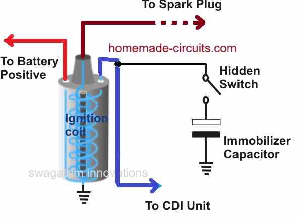
Referring to the above simple cheap vehicle immobilizer circuit, we can see that the whole circuit is fundamentally comprised of only a single passive component a high voltage capacitor (10 uF/400V).
As we all know capacitors have the property of grounding any signal that is made up of some kind of frequency, or rather a capacitor will always allow an AC to pass through it.
This property is well exploited here to get the required security feature from the proposed circuit.
All vehicle system primarily utilize their ignition system for starting and for sustaining their engine movements. Thus the ignition system becomes the heart of the vehicles as far as their working is concerned.
The ignition system works by igniting a fuel mixture inside the ignition chamber through consistent high voltage arcing. This high voltage arcing is generated from the ignition coil.
Therefore, finally we know that it’s the high voltage arcing that needs to be inhibited to stop the vehicle or for making it completely immobilized.
By introducing a high voltage capacitor across the main ignition high voltage source and ground, we can easily terminate the passage of the high voltage pulses to the spark plugs and completely disable the ignition process.
As shown in the figure this is simply done by connecting the capacitor leads to the relevant points.
However if you wanted to override the system you could easily do it by disconnecting the capacitor from the system, simply by activating a hidden switch.
This switch can be placed somewhere inside the bonnet or in some hidden place that would be known only to you.
For the installation of the entire wiring, you can take the help of a professional cat electrician.


Questions & Answers
Shouldn’t the hidden switch be connected to the low voltage negative terminal on the coil? Not cut into the high tension lead which goes to the distributor!!!
You are right, I have corrected the diagram accordingly, thanks for pointing it out…
could you possibly help me try to bypass my 2004 acura tl and its stubborn immobolizer. ive tried every possible way i could come up with. the car is a project car of mine and i recently had it shut down on me during a modification.im stumped and canT seem to get the daMN THING TO FIRE.LOL IT JUST CRANKS AND CRANKS.
Sorry, I do not seem to have any idea regarding the issue.
Why not just install that switch in series with the spark plugs and ditch the capacitor? What will be the difference?
A series switch can be easily traced and bypassed, a capacitor based wiring away from the actual ignition system can be a lot difficult to trace.
Also since the main ignition wire will be connected with the supply, the thief will be confused regarding its immobilization, until he reads this article.
Lol. Awesome. I’ll be sure to leave a paper with the link to this article next to the ignition coil for the thief:)
On a side note, my car does not have a light bulb in the trunk/boot (cheap car). I have been thinking of building a circuit that will switch the light on automatically when one opens the boot (the way a car should be). I believe the concept is the same as a fridge door. I hate using a torch to remove items(like grocery) from the boot at night. Any ideas.
I’m a huge fan of this site. I just discovered it now.
Thanks again for all the wealth of info you are sharing with us without charging a dime and your speedy response.
Thank you childs, I’m glad you are liking my website, keep up the good work!…yes, the thief and myself will be thankful to you for that lol!
The fridge door circuit can be used, however a simpler alternative can be also tried using a just a couple of transistors and a reed switch, I may try to update it in the fridge door article soon…. or even more simply a press switch can be installed somewhere near the hinge that will pres a switch and illuminate the connected bulb.
In ur spy bug project what is the polarity of C5 in 2nd circuit