• Skip to main content
  • Skip to primary sidebar

Homemade Circuit Projects

Need circuit help? Post them in the comments! I've answered over 50,000!

Blog | Categories | About | Hire Me | Contact | Calculators-online
You are here: Home / Audio and Amplifier Projects / Power Amplifier Circuit using IC 741 and MOSFET

Power Amplifier Circuit using IC 741 and MOSFET

Last Updated on May 15, 2026 by Swagatam 10 Comments

In this post we study a power amplifier design configured using an ordinary IC 741 and a couple of MOSFETs.

Table of Contents
  • Circuit Description
    • Parts List
    • How to Adjust the Quiescent Current
    • Specifications

An operational amplifier's output power such as from an IC 741 can be typically enhanced when a complementary emitter follower transistor is coupled at its output. The same could also generally be accomplished using a MOSFET.

By Rakesh More

However, it is not necessarily a smart idea to connect MOSFETs like a complementary source follower simply because the maximum output voltage of the op amp can now be decreased substantially through the MOSFET's gate-source control voltage, which is often a few volts.

A better technique would be to hook up a couple of MOSFETs like a complementary drain follower circuit. This method has been discussed in this proposed IC 741 MOSFET power amplifier circuit article.

Circuit Description
Parts List

CategoryComponentValue/TypeQuantity
ICIC1741 Operational Amplifier1
TransistorsT1, T2 NPN BJT2N39042
T3 P-channel MOSFETIRF95201
T4 N-channel MOSFETIRF5201
ResistorsR1, R2100 kΩ 1/4W 1%2
R3100 kΩ 1/4W 1%1
R4, R51.3 kΩ (1.2 kΩ + 100 Ω) 1/4W 1%2
R62 kΩ 1/4W 1%1
R7330 Ω 1/4W 1%1
R81 kΩ 1/4W 1%1
R9240 Ω 1/4W 1%1
R10, R11100 Ω 1/4W 1%2
PresetP11 kΩ 1/4W 1%1
SpeakerLS8 Ω, 20 W1
Power Supply-±20 V (dual polarity)1

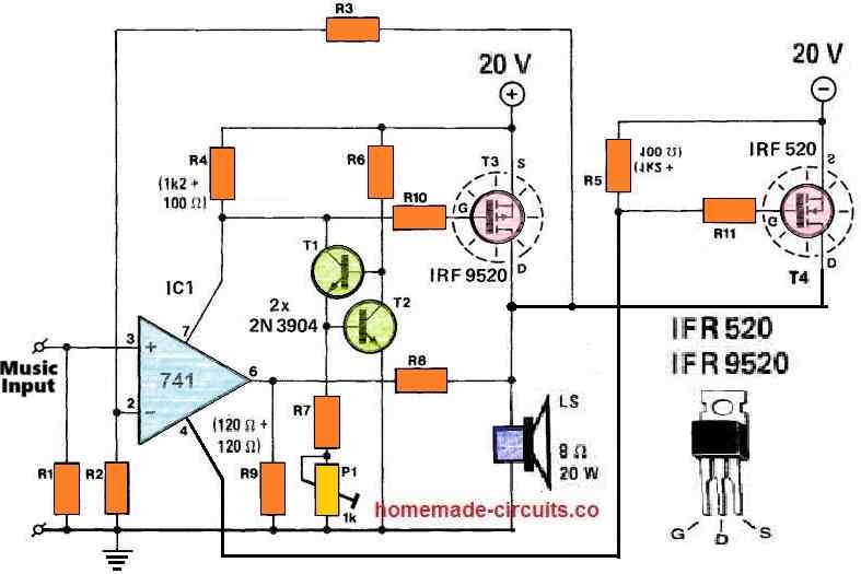
The (switching) output current supplied by the MOSFETs is restricted by the amount of the supply voltages and the saturation voltage outputs from the transistors T3 and T4.

Resistor R8, along with R9, delivers feedback for the opamp and the MOSFETs both. The 741 op amp's open-loop amplification is, consequently, improved by (1 +R8/R9).

The closed-loop amplification of this amplifier design is defined by the value of the expression (1 +R3/R2).

The current source established by T1 and T2 is necessary for creating the quiescent current of T3 and T4 at 50 mA. The R4 and R5 should be such that, in the absence of the current source, the drop in the voltage across the resistors caused by the DC through the opamp is inadequate to switch on T3 and T4.

In the presence of the current source, and depending on how the preset P1 is adjusted, the voltages across R4 and R5 increase which in turn causes the quiescent current through T3 and T4 to increase.

With regard to the temperature dependence of the quiescent current, T2 should be installed on the common heatsink alongside the MOSFETs.

How to Adjust the Quiescent Current

Quiescent current refers to the current consumption of the amplifier during its idle state or in a situation when the volume control is reduced to the minimum level.

The quiescent current of the amplifier can be adjusted through the following points.

  • Procure two 100mA 24V bulbs from market.
  • Connect these bulbs in series with the +/- supply lines of the amplifier.
  • Short circuit the input terminal to ground.
  • Connect a speaker at the output.
  • Next, switch ON power, the bulbs should illuminate brightly.
  • After this, adjust the P1 preset until the bulbs just shut off or the illumination becomes almost zero.
  • That's all, the quiescent current of the amplifier is not set.
  • Remove the bulbs and restore the circuit to its original form.
  • Now you can use the amplifier normally without the danger of over heating the MOSFETs during idle conditions.

Specifications

The output power of this 741 MOSFET power amplifier circuit is approximately 20 W into a 8 Ohm loudspeaker.

At this power specifications the total harmonic distortion of the design can be expected to be around 0.075% at 100 Hz and to 0.135 % at 10 kHz.
You'll also like:

  • digitized music circuit compressedAudio Dithering Circuit for Enhanced Crisper Music
  • one transistor radio circuitSingle Transistor Radio Receiver Circuit
  • Voice/Audio Recorder Playback Circuits
  • V shape antennaFM Signal Booster Circuit with Adjustable Gain

Filed Under: Audio and Amplifier Projects Tagged With: 741, Amplifier, MOSFET, Power

About Swagatam

I am an electronics engineer and doing practical hands-on work from more than 15 years now. Building real circuits, testing them and also making PCB layouts by myself. I really love doing all these things like inventing something new, designing electronics and also helping other people like hobby guys who want to make their own cool circuits at home.

And that is the main reason why I started this website homemade-circuits.com, to share different types of circuit ideas..

If you are having any kind of doubt or question related to circuits then just write down your question in the comment box below, I am like always checking, so I guarantee I will reply you for sure!

Previous Post: « Audible Meditation Timer Circuit
Next Post: 7 Automatic Street Light Circuits [Using Relays and Solar Panel] »

Reader Interactions

Questions & Answers

Total Posts: 10
Newest Oldest
Prof. A.K. Mahato
June 16, 2022 • 4 years ago #126744

Can you share your contact number ? I am in need of a complete, professional grade 50 – 100w RMS stereo amlifier with matching transistorised preamplifier and tone control, soft starter, speaker protection, etc. Will you please design such a hi fi project ?
With warm regards.
A.K. Mahato

Reply
SwagatamAdmin
June 16, 2022 • 4 years ago #126746

Sorry, that looks quite complex, designing a professional grade stereo amplifier with all those specifications is beyond the level of my expertise.

Reply
Carlos
June 21, 2022 • 4 years ago #128266

can you do me a favor? I need a circuit for audio fix.. I need a signal tracer and signal injector… They may both be on the same circuit.
Thank you.

Reply
SwagatamAdmin
June 22, 2022 • 4 years ago #128321

I have an exclusive article on signal injector, which you can find here:
https://www.homemade-circuits.com/signal-injector-circuits-for-quick-troubleshooting-of-all-audio-equipment/
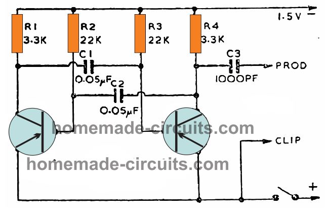
If you want an easier circuit you an try the following design:
audio fault finder
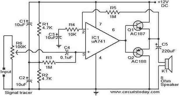
I do not have a signal tracer circuit with me, so I searched it online and found the following design:
signal tracer circuit

Reply
Agweny
January 16, 2023 • 4 years ago #138994

Greetings Swagatam
I would like to know if You Can Ast sist with A Circuit for Prepaid KWh Meter.
I’ve been trying weather I could create it out of a timer but I ended up using A Circuit breaker to control my tenants on Yaka, very laborious and time intensive due to the need for constant Monitoring. At the same Time the dealers in those gudgets proved to very expensive and arrogant.
Agweny Richard
agwenyrichard@gmail.com

Reply
SwagatamAdmin
January 16, 2023 • 4 years ago #139000

Hello Agweny, sorry, I do not have a prepaid KWh meter circuit with me at this moment.

Reply
Clair Morrill
March 30, 2023 • 4 years ago #141482

Swagatam, the above circuit was developed by Silliconix. in the original circuit they used a TL071 not a UA741. I bought the original application and data book in the mid 90’s. Sincerely,Clair Morrill.

Reply
SwagatamAdmin
March 30, 2023 • 4 years ago #141489

Thank you Clair, I hope the readers will find this information useful. The above post was contributed by an external author so maybe he made a mistake while entering the op amp number.

Reply
Clair Morrill
February 21, 2025 • 2 years ago #168557

This Class A audio amplifier is capable of putting out up to 50 watts peak power, Sincerely, Clair Morrill

Reply
Хосе Аморалис
May 11, 2026 • 5 months ago #206764

Схема в железе работать отказалась. И если для смещения применяются резисторы на 1,4 ком, то питание должно быть обязательно стабилизированным!

Reply

Need Help? Please Leave a Comment! We value your input—Kindly keep it relevant to the above topic! Cancel reply

Your email address will not be published. Required fields are marked *

Primary Sidebar

My YouTube Channel

Circuit Simulator: Draw and Simulate Schematics

circuit simulator image

Categories

  • Arduino Projects (95)
  • Audio and Amplifier Projects (134)
  • Automation Projects (18)
  • Automobile Electronics (104)
  • Battery Charger Circuits (90)
  • Datasheets and Components (109)
  • Electronics Theory (151)
  • Energy from Magnets and Earth (43)
  • Games and Sports Projects (11)
  • Grid and 3-Phase (20)
  • Health related Projects (27)
  • Home Electrical Circuits (13)
  • Indicator Circuits (16)
  • Inverter Circuits (98)
  • Lamps and Lights (161)
  • Meters and Testers (72)
  • Mini Projects (28)
  • Motor Controller (68)
  • Oscillator Circuits (30)
  • Pets and Pests (15)
  • Power Supply Circuits (91)
  • Remote Control Circuits (50)
  • Security and Alarm (65)
  • Sensors and Detectors (107)
  • SMPS and Converters (46)
  • Solar Controller Circuits (62)
  • Temperature Controllers (44)
  • Timer and Delay Relay (51)
  • Voltage Control and Protection (44)
  • Water Controller (37)
  • Wireless Circuits (31)

Subscribe to get New Circuits in your Email

Other Links

  • Privacy Policy
  • Cookie Policy
  • Disclaimer
  • Copyright
  • Videos
  • Sitemap

People also Search

555 Circuits | 741 Circuits | LM324 Circuits | LM338 Circuits | 4017 Circuits | Ultrasonic Projects | SMPS Projects | Christmas Projects | MOSFETs | Radio Circuits | Laser Circuits | PIR Projects |

Recent Comments

  • Michael on Electronic Circuit Projects, Tutorials, and Practical Engineering Solutions
  • Swagatam on 24V to 12V DC Converter Circuit [using Switching Regulator]
  • Swagatam on Automatic Battery Full Cut-Off Latching Circuit with Trickle Charging
  • Ramin on Automatic Battery Full Cut-Off Latching Circuit with Trickle Charging
  • Joss on 24V to 12V DC Converter Circuit [using Switching Regulator]

Social Profiles

  • Twitter
  • YouTube
  • Instagram
  • Pinterest
  • My Facebook-Page
  • Stack Exchange
  • Linkedin

Calculators

  • ZVS Induction Heater + Tank Calculator Tool
  • Zener Diode Calculator
  • Wire Current and Thickness Calculator (Ampacity Calculator)
  • Voltage Divider Calculator
  • Transistor Base Resistor Calculator
  • Transistor Astable Multivibrator Calculator
  • TL431 Calculator
  • Solar Panel, Inverter, Battery Calculator
  • Ferrite Core Air Gap Calculator Tool
  • Parallel MOSFET Calculator Tool: How to Connect MOSFETs in Parallel Safely
  • LC Resonance Calculator for EV Battery Charger Circuits
  • LED String Series Resistor Calculator
  • PFC (Power Factor Correction) Calculator Tool: 3kW
  • Passive Power Factor Correction (PFC) Calculator
  • LM567 IC Calculator Tool
  • SMPS Flyback Boost Converter Calculator
  • Shunt Resistor Calculator for Ammeters
  • SCR and Triac Gate Resistor Calculator
  • Battery Back up Time Calculator
  • Boost Converter Calculator (Non-Isolated)
  • Bootstrap Capacitor Calculator
  • Buck Converter Calculator
  • Buck-Boost Converter Calculator
  • Capacitance Reactance Calculator
  • DCM Flyback Transformer & Wire Gauge Wire Size Calculator Tool
  • Filter Capacitor Calculator
  • IC 4047 Calculator (Frequency and PWM)
  • IC 4060 Calculator
  • IC 555 Astable Calculator
  • IC 555 Monostable Calculator
  • IC SG3525, SG3524 Calculator
  • Inductance Calculator
  • Induction Heater Inductor and Resonant Frequency Calculator
  • Induction Heater Work Coil Calculator
  • Inverter LC Filter Calculator
  • LC Resonance Calculator
  • LED Current Calculator
  • LM317, LM338, LM396 Calculator
  • NAND/NOT Gate RC Values Calculator
  • NOT, NAND Gate Frequency Calculator
  • Notch Filter Calculator Tool
  • Ohm’s Law Calculator
  • Phase Angle Phase Shift Calculator
  • Power Factor (PF) Calculator
  • RC Filter Calculator
  • Reactance Calculator
  • Sine Table Calculator for SPWM Arduino Code
  • Small Signal Transistor(BJT) and Diode Quick Datasheet
  • SMPS Calculator for Toroidal Ferrite Transformers
  • SMPS Flyback Transformer Calculator – Design by Target Duty Cycle
  • TL431 Calculator
  • Op-Amp Hysteresis Resistor Calculator

© 2026 · Swagatam Innovations