In this post I will show how to construct a timer circuit for meditation practices which gives out beeping sound between 1 and 9 seconds (user selectable) and this beeping audio can be integrated with your mediation session, we will see how we can integrate the periodic beeping with “mindfulness meditation” as example in later part of this post.
The proposed project is for the people who consider themselves as beginners, the beeping tone is for guiding the amateur meditator throughout the meditation session.
Let’s see the block diagram of the project:
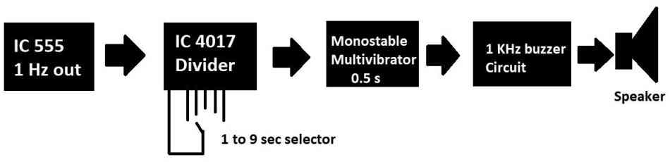
Let’s try to understand the above block diagram from left to right. The left most blocks consist of a clock generator which outputs approximately at 1 Hz. It is built using evergreen IC 555.
The 1 Hz clock is fed to the next stage called clock divider circuit; this block divides the 1 Hz signal to one pulse for every 1 to 9 seconds and here the meditator can adjust as per his/her requirement.
The signal from the divider circuit lasts only for a few microseconds which is not enough to trigger a buzzer, so we need a monostable multivibrator circuit which picks the narrow pulse and converts it to an output that lasts for a predetermined period of time.
The output of the monostable stage is fed to a buzzer circuit which is basically an astable multivibrator clocked at 1 KHz to produce 1 KHz sound on the speaker.
Now let’s implement it practically.
1 Hz generator stage:
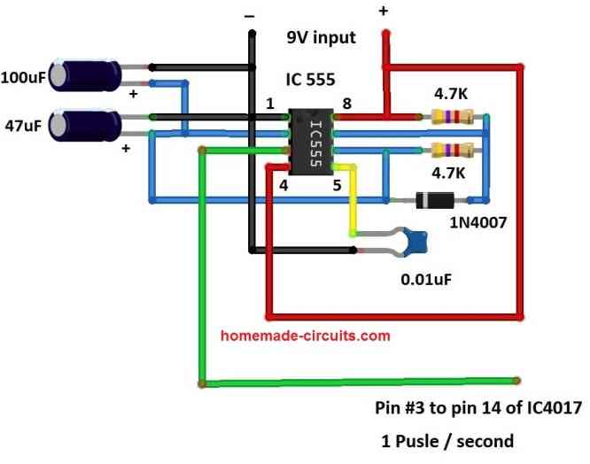
Here the circuit is built using IC 555 and configured as astable multivibrator, around the IC we have some passive components such as resistors and capacitors and one active element diode.
The values of resistors and capacitors are carefully chosen to produce clock output at the rate of 1 Hz. The purpose of the diode is to make the clock output 50% duty cycle.
The two capacitors at pin 2 are connected in parallel to get a combined value of 147uF, which fixes the required 1 Hz timing output. A 0.01uF capacitor at pin 5 is for stabilizing the output signal, skipping this capacitor will leave the IC vulnerable to external electrical noise and you will not get the intended 1 Hz output.
The above circuit and also the rest of the circuit are operated on a 9V battery or 9V supply.
Clock divider circuit:
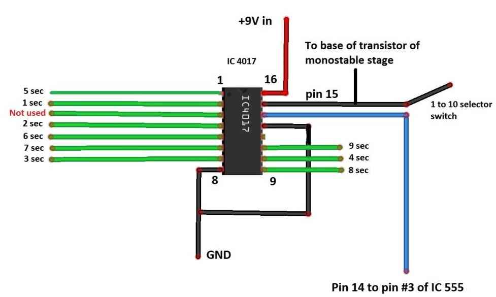
The heart of the above stage is an IC 4017 which is a counter that can count from 0 to 9. There are 10 output pins and for each clock pulse applied at pin #14, it increments the output by 1 position.
The output pins of IC 4017 sequence in the following order : 3, 2, 4, 7, 10, 1, 5, 6, 9, and 11.
Initially the pin output #3 will be high and when a clock pulse is applied at pin #14, the pin #3 turns low and pin #2 turns high and when another clock pulse is applied pin #2 gets low and pin #4 gets high, this is true for all the subsequent output pins.
The reset pin #15 should be connected to the output pin for your desired output time. For example if you want beep for every 5 seconds, you need to connect the pin #15 to pin #1.
For ease of use you can utilize a 1 pole 10 ways rotary switch or DIP switch for selecting the beeping time.
Monostable and buzzer stages:
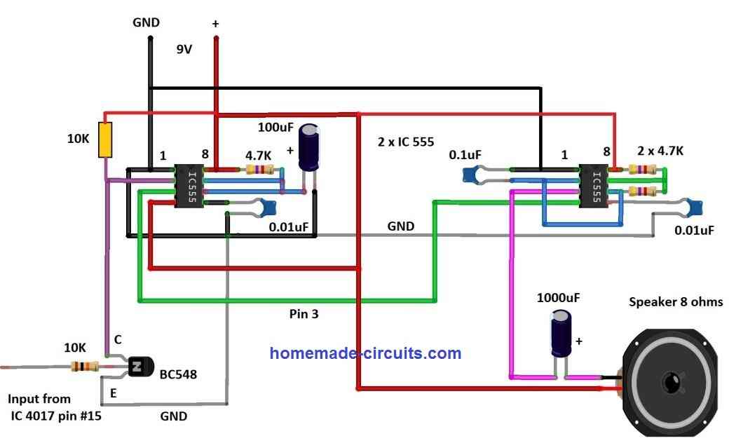
The above circuit consists of two stages, the left hand side’s IC 555 is configured as monostable and the IC at the right hand side is configured as astable multivibrator for generating beep.
The monostable multivibrator outputs high signal for 0.5s when a narrow negative pulse gets applied at pin #2. During idle state the pin #2 is pulled high using a 10K resistor. The 4.7K and 100uF capacitor gives us approximately 0.5s output, hence the audible beep duration.
The signal from IC 4017 is applied to base of the transistor, when it receives a high signal the transistor turns ON (outputs low) and since the output terminal (collector) is connected to pin #2, the monostable circuit outputs a high signal for 0.5s.
The output of monostable stage is connected to pin #4 of IC 555 (at R.H.S) astable stage. When pin #4 (at R.H.S) gets high, 1 KHz oscillation starts at pin #3 where the speaker is connected. When pin #4 gets low signal no oscillation will be at pin #3 hence no beep.
A 1000uF capacitor is connected between pin #3 and speaker, so that no DC current passes and only 1 KHz signal passes through the speaker.
This concludes about the circuit.
How to integrate the beeping tone with a meditation session?
You can use this timer for any suitable meditation technique; here I am going to show you how to use this timer for mindfulness meditation.
If you don’t know what mindfulness meditation is, well here is a brief explanation.
In mindfulness meditation practice you need to concentrate on your breath while breathing in and breathing out and think about nothing (no chanting, no visualization etc.)
However, at some point, your mind starts wandering about something (for sure as a beginner), now you need to gently bring your concentration back to breath. This session can be 5, 10, 15, or 20 minutes depending on your level of patience.
Bringing back the concentration to breath can be difficult especially for beginners, they may not even be aware that they are mind wandering.
So to make things easy an external interrupt (a beep) can remind you about unwanted thought processes and bring your concentration back to breath.
Now let’s see how to use the timer:
- Sit in any comfortable position you wish, keep the back straight and you may get support from a wall or chair for your back.
- Set the timer for 5 seconds (say) and power it on.
- When you hear the first beep, breathe in gently and when you hear the next beep breath out gently. Now your concentration should be on the breath.
- At some point soon, your mind starts wandering even though you won’t be aware. When you hear a beep toggling, your breath brings back your concentration. The stronger your concentration on your breath the lesser are the intruding thoughts.
- Continue this session for any number of minutes you wish every day.
The benefits of mindfulness meditation are immense so please do a Google search.
Similar to this meditation practice, you can use this timer for any other meditation practice especially that involves some kind of timing or your concentration.
Now let me answer a question that could be in your mind, why can’t we use a smartphone for this kind of purpose?
Well, smartphone equals distraction, say you are meditating and a notification pops-up this is enough to ruin your concentration, neither you won’t pick the phone while meditating nor you won’t stop thinking about the notification like who was it, is it important etc. because our mind’s concentration power can be that fragile for many people.


Questions & Answers
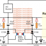
I was looking at your meditation timer. I need an intermittent buzzer that will give a short sound every minute or two. I have a 555 timer circuit using a potentiometer, 9v battery, 6ea 100 uf capacitors, and a buzzer. It works but beeps every 4.25 seconds which is too fast. I’m very new to electronics and was surprised to be able to make this circuit but I’m looking for help to have it beep with a longer (1 minute) pause between beeps. Thanks in advance for your insight. Jeff
You can adjust the potentiometer (between pin#7 and the positive) and the capacitor (between pin6/2 and ground) to get the desired output range.
Just make sure to add a 10uF capacitor in series with your buzzer. This will enable the buzzer to switch ON momentarily, and produce only short beeps.
Thanks so much!