In this article I have explained a single chip circuit which can be used for recording and playing back short voice clips or any audio clip ranging from 20 to 60 seconds.
About the IC APR9600
The incorporated IC APR9600 is a programmable voice recorder chip which facilitates infinite number of recording/erase of audio files in it as per user preference.
The recording or storage of the audio can be done through an integrated electret mic or via any line out or RCA port of an audio reproducing device.
However since the IC is a low bit device does not support Hi-Fi recording rather low quality music.
The sampling rate or the frequency response is limited to just 8 kHz max that's pretty ordinary if we compare it with the specs of modern Hi-Fi equipment.
Nevertheless, the IC is a stand alone device which does not depend on any external circuits, just plug it in, and it starts recording whatever voice data is fed across its input pins. Moreover since the data can be erased and refreshed any number of times, the unit becomes completely programmable and a pretty useful gadget.
Circuit Diagram
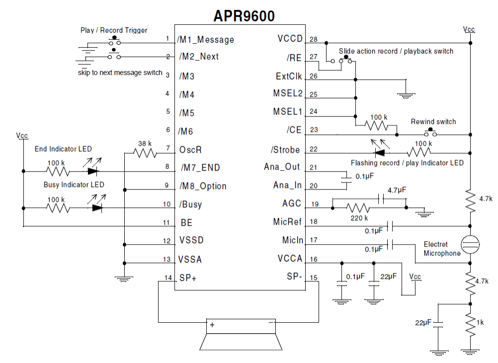
Image courtesy: https://www.datasheetcatalog.org/datasheet/aplus/APR9600.pdf
Circuit Operation
The proposed circuit of a programmable single chip voice recorder/player utilizes the IC APR9600 as the main processor of the circuit.
It's a 28 pin IC which can be very easily and quickly configured for getting the required results by adding a handful of common passive electronic components.
All the pin outs of the IC are specified by their individual functions, and the components are accordingly attached with the respective pinouts.
For example pin#28 and pin#27 are assigned as the trigger inputs for initiating playback and recording functions.
Sliding the connected switch toward right initiates the playback action while toggling it toward left puts the IC in the recording mode.
The IC also has appropriate visual indication options which provide the user with instant information regarding the position of the circuit.
The LED at pin#8 indicates the end of a playback file session.
The LED at pin#10 stays illuminated for so long the audio is being played, indicating circuit "busy"
The LED at pin#22 indicates through rapid flashes regarding the playback or recording modes of the IC.
The input data is normally picked from the mic which is appropriately connected across the pins 17 and 18 of the IC.
When the slider switch is pushed toward the recording mode, any audio entering the mic gets stored inside the IC until the specified time elapses.
The sampling rate of the IC can be set as per the user preference. Lower sampling rates will provide longer recording/playback periods and vice versa.
Longer periods would also mean lower voice quality while shorter periods of recording spec will produce relatively better sound processing and storing.
The entire circuit operates with a 5 volt supply which can be acquire through a standard 7805 IC after rectification from a standard transformer bridge capacitor network.
The audio output may be derived across pin#14 and ground which must be terminated to an audio amplifier so that the data can be heard with proper volume.
Audio Record/Playback Circuit using IC ISD1820
The second concept explains the functioning of the IC ISD1820 which is a single chip audio message record/playback chip featuring a 20 second audio recording and storing facility in its internal memory and playing it back through a small 8 ohm speaker whenever required.
Introduction
The IC ISD1820 is a device which features a single chip audio message recording and playback facility, and is able to retain the audio message in it infinitely even while the chip in the un-powered state.
The recording-playback and erase cycles can be implemented as many as 100,000 times without any form of degradation, that’s so huge and looks almost infinite in this regard too.
The maximum recording an playback time available from this chip is no longer than 20 seconds.
The technical features of this record/playback module IC ISD1820 can be studied below:
1) Can be operated with DC 2.4V to 5.5V
2) Includes an internal audio amplifier circuitry capable of handling a 8 ohm ½ watt speaker directly at its output.
3) Works with a standard electret MIC as the input audio or voice detector.
Pinout Functions:
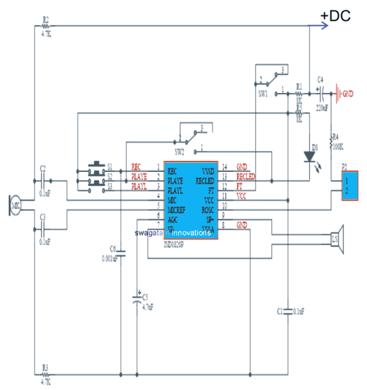
Referring to the proposed 20 second message record/playback circuit diagram using the IC ISD1820:
1) Pin#1 can be seen as the REC (recording) input pinout, which accepts a positive signal for enabling the recording function, meaning this pinout must be connected to the Vcc or the positive line while recording an audio clip,
The REC pinout has the ability to take precedence over the other pinouts marked PLAYE/PLAYL in case it is pulled high while any of the other pinouts were functioning.
Meaning suppose if any of the PLAY button was pressed, and simultaneously REC was pressed, in such case the recording (REC) will be immediately initiated terminating the PLAY action.
The voice recording action can be stopped as soon the relevant button is switched OFF, and the REC pinout is rendered at LOW. In this position an internal EOM or end of message prompt is triggered internally, causing the PLAYBACK mode to get in the ready position. This also causes the chip to go into a power down condition or in the standby condition.
2) PLAY pinouts: As can be noticed in the diagram, the IC facilitates two PLAY pinouts, which are PLAYE, and PLAYL. PLAYE allows an logic edge activated triggering, while PLAYL facilitates a logic-level activated triggering of the playback.
In the PLAY E or edge activated mode, a single press and release or a momentary press of the button will initiate the playback of the recorded clipping through the speaker, and will end as soon as the internal EOM (end of message) signal gets activated.
The PLAY L mode is activated when the attached button is pressed and held pressed without releasing it. The audio playback now continues as long as the button remains depressed, or as soon as the internal EOM is activated. Keeping the button permanently pressed will cause a higher current consumption of the IC.
Other than the REC and the PLAY buttons, this audio record/playback circuit additionally possesses a couple of switches associated with the chip in the form of SW1 and SW2. SW1 is positioned for the “Feed Through” action while SW2 for the “REPEAT” functioning. Let’s understand them in detail.
As may be witnessed, the SW1 is configured with the “FT” pinout of the IC which refers to “Feed Through”.
When actuated in the feed through mode, the signal across MIC, and the MIC_REF pinouts are bypassed through the AGC pinout of the IC, up to the the filter driver stage and finally reaching the speaker points (SP+ and SP-)
The FT input signal is responsible for controlling the feed through mode of the chip. In order to be initiated the feed through mode, the pinout FT is held at the positive Vcc logic, while the REC, and the PLAY buttons are at low logic or with their buttons in the deactivated positions.
SW2 is used for enabling the REPEAT mode, which implies that when this switch is toggled ON the playback goes on repeating the recorded message clip through the speaker non-stop, until the switch is toggled OFF.


Questions & Answers
HI!
I am an artist who wished to purchase 30 or so microchip boards that I can imbed in a painting… one song on each board….when they push the button, it plays a song for up to 3 minutes. I think it would need to have a small speaker attached. I cant figure out what to call this and looked through your work….. so, I guess it would be called an IC ? Please let me know if something like this could be fashioned and what it would cost. If you cant help me. could you direct me to someone who could? I appreciate your technical knowledge and skill. Thanks
Annie
Hey, Annie,
You can buy these modules from any online store like Amazon….if you search for “recordable chips” or “recordable modules” you will be able to find many good options, however these modules are not very small, rather look biggish with the speaker connected, and are also pretty expensive at around $10 each, minimum… However the nice thing is that you can prerecord a song of your choice in these modules and then play it back through push buttons for 4 long minutes.
Sorry, it won’t possible for me to assemble the whole unit for you, due to my busy schedule…if possible I may try to find someone else and let you know…
Thanks so much for your advice.
How do you delete audio files? I’m trying to make a voice recorder and will also need to delete audio when the user is done with it.
I think these voice recorders do not have a separate erase function. Instead, they store recordings for a set duration. Once full, the oldest recording is automatically overwritten to make space for a new one.
Is there a chip with better fidelity and multiple file record and play
what i need is a very cheap voice recorder and even multiple times or eternal you playback a recorded voice same message as it is.and even you remove it’s power supply,when returning it back,still same recorded message every time you pressed a play button.
Hi, The above circuits can be setup to do that.
really?thanks a lot sir,i need to use this circuit for every time there is any sensed seismic activities and will give immediate warning through the help of loud amplifier.i;m still developing a sensor circuit and it;s mechanism for a better much sensitivity.it might be a big help.so thanks a lot sir and more power
You are most welcome Aristotle, I appreciate your valuable feedback!
Sir I’m looking for a circuit for making talking cactus toy,which repeat what we said after the moment we stop talking in a funny voice.can you help me? Please…
Deepu, sorry I do not have this circuit with me right now.
I am interested in your chip, I think, if it is affordable. I work with special education children and I am looking for a way to record a letter name, or its phoneme and imbed it in a reusable laminated binder for morning work that can be self guided. The student would have a series of words that begin with the same letter, but the starting letter is missing. They push YOUR button and hear my voice making the sound of the letter. They have to find the matching letter for that sound and attach it to the series of words using a Velcro attachment. Does this sound like something your mechanism can do? I would need over a hundred of them so they would have to be inexpensive.
Yes, it should work for your mentioned application, however, unfortunately we don’t manufacture this item, so we won’t be able to provide it to you!
Hi,
Do you know of any similar looping circuits & components that would facilitate a longer recording/playback time? Say for example 10-30 minutes as opposed to 20 seconds?
Thanks in advance
Isd4004
Hi, I don’t think such chips are manufactured at the present time…I tried searching but could not find any relevant results, except the gadgets that are available on amazon or other online store
hi, i want to make a smart blind stick and have an audio as the output. can you recommend either ISD1820 or APR19600 is better?
Hi, both are good, you can use anyone which suits your specifications…
Regarding the ISD1820.
I’m trying to use the Speaker output (SP+ SP-) to drive a line input of another preamp (eg. radio or USB/Bluetooth speaker with 3.5mm input).
I don’t seem to get more than 0.3V AC signal out of it. I was hoping for over 1V into a high impedance (I assume 1K but atleast a lot higher than 8 ohms).
It appears the AGC circuit limits the volume and I can never increase the output despite increasing the input level.
Is there an easy way to preset the recording volume or increase the output?
Thanks,
When the circuit is able to drive an 8 ohm speaker loud, it means its output is sufficiently high to drive even a power amplifier input. So the output peaks should be easily above 1 V or even equal to the supply voltage.
However, to make it work you must make sure that the external peramplifier and the ISD1820 circuit both share the same power supply lines, or least the ground line must be connected in common.
Hello Swagatam,
Do you have any application similar to talking tom toy. It will play back the voice soon after recording is finished.
Thanks in advance.
Hi Ritesh, Sorry I do not have this project in this website at this moment.
Good day sir please, can you help me with any recording circuit which when recording it will also be stored in either USB or memory card i.e I can link usb or memory card to the circuit, is there any ic that can do that I really need it
Faith, that may be surely possible, but sorry I do not have any information or circuit regarding this subject at this moment.
Sir I come across this components WT2003S-16S, I can use both Sd card/ usb drive but what I’m not sure is if the ic can use without programming i.e either microcontroller or Arduino
Faith, it is not mentioned in the datasheet so I too cannot figure out the specifications.
Question re: APR9600…pins 1,2,3,4,5,6,8,9 imply different messages? Will this chip store eight different messages of say 20 seconds each? I’m building a fire alarm for my house and want it to announce what room the fire is in.
Thank you for your time, Marc Estrade
No, the circuit cannot store 8 different messages.
Thank you for helping. Unfortunately, I only have a very limited knowledge of circuitry.
Can I hook up an external switch to make the device playback instead of pushing the button on the board itself?
If so, where do I connect the two switch leads? Thanks again.
Yes, you can use an external switch, but the switch will depend on which mode you wish to have. Please read the PLAY L and PLAY E functions, and accordingly you can use a push-to-ON switch or a toggle switch. The switch terminals can be connected across the indicated pin2 or pin3 switch terminals.
is there anyway to increase length
you will need a 64 bit IC for that…different "bit" ICs are available for different time lengths..
SIR, i face problem that i cant get all the components locally, so please recommend me an online address that i can get all components. and of quality and reasonal price.
thank you very much.
Manjunath, you can try mouser, digikey, sparkfun etc these are all reputed online parts dealer
put .com beside the above names while searching
dear sir,
nice circuit sir
i don't want the recorder section instead of this i want to play preloaded tone, so what should i have to do. thanks in advance..
thanks and regards
yuvarajan.m
DearYuva,
Do you mean you want a preprogrammed musical IC, like UM66 etc.
Can you help me? I have an ISD 1820 circuit board. How can I hook a switch to play the playback instead of pushing the play button on the board? Thanks so much.
Jamie Goncharoff
Thank you’re a gentleman. I’m using PLAY E. I push the play button and it plays the recording once.
For my switch, either toggle or push button, I need to make two connections.
Sorry, but which two pins do I use for the connections. Thanks.
You will have to connect wires across the switch points shown in the diagram, just extend those points through wires, and connect your switches with these wire ends. Connect push-button to play E button points, and SPDT switch across play L switch points.
Yo! Would it be possible to somehow trigger the playback as soon as recording ends ? or even better, about 2 seconds after ? thanks
May e possible, but can make the circuit very complex.
Hello, I think the details are given in the article, please read it!