In this article I have explained a simple circuit concept which can be used to transform an ordinary analogue audio signal into a much vibrant and crisper digital music, by adding an external random noise to the audio, which is also known as pink noise.
Video dithering is a procedure for generating an image file which may have a enhanced realistic look.
In this process the content for the color of each pixel are added or deducted with aggressive values.
This approach delivers a deviation to the image which provides an extra effect to the texture which looks richer than the normal smooth, monocolor images.
The greater the dithering added, the more deviant the final effect is.
The above description explains how a video can be enhanced through the method of dithering, but you may be still wondering what exactly is audio dithering?
How does dithering technology help to transform a low quality analogue audio signal into a rich, crisper digital audio?
What is Audio Dithering
The principle implemented to achieve video dithering also identically applies for audio technology.
When an external randomly sampled noise is added to an analogue audio signal, it breaks the audio into more granular form, transforming it into a more vibrant and interesting sound which is more pleasing to our ears.
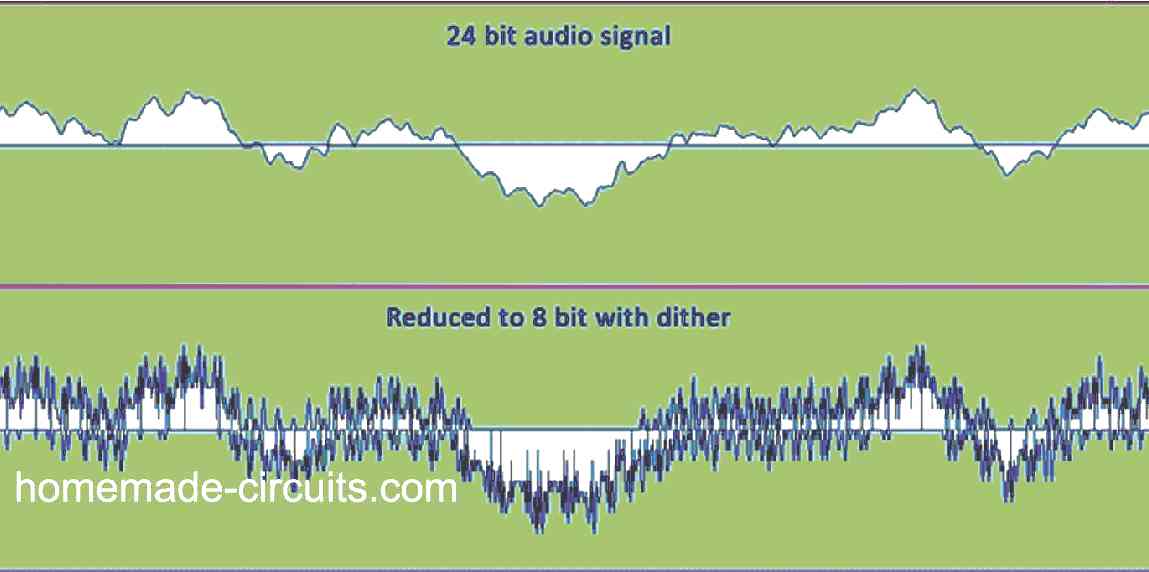
The higher the random noise added to the input music, the greater will be the deviant output. In the proposed dithering circuit since we use an A/D converter that breaks an analog wave into sections, a resultant sinewave appears quite like the Fig. 1A; if some more dithering is added, the output may look like Fig. 1B.
Dithering passes across every single step repeatedly rather than just once.
This implementation provides a digitized output which is a lot more gratifying to hear and might even turn an unclear distorted digitization into something which may be a lot more attractive to hear.
By simply applying the dithering method, a 1 bit, 10-kHz sample can reach through an absolute rubbish to a well-known figure.
The miracle range for noise input is approximately 70% of 1 bit. This means that , if you apply an input of 8 bits with a input signal of 2 V peak-to-peak, the noise level to be induced will be:
- Vnoise = Vinp-p / 2n bits x 0.7
- Vnoise = Vinp-p / 28 x 0.7
- Vnoise = 2 / 256 x 0.7
- Vnoise = 5.5 mV
How the Circuit Works
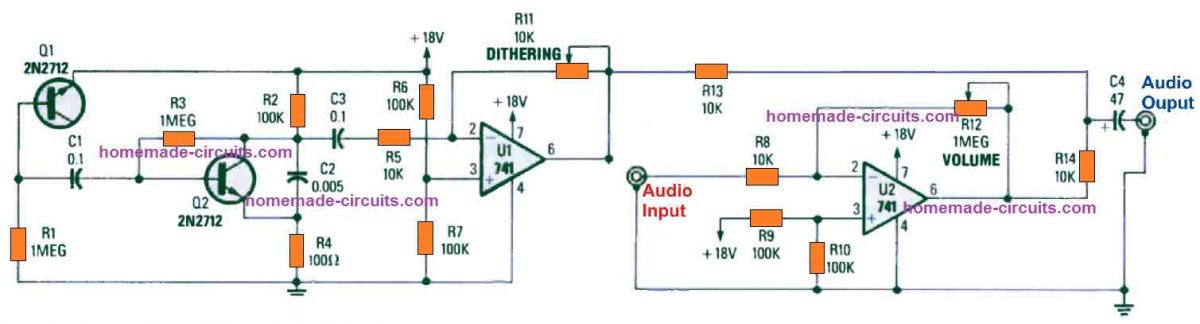
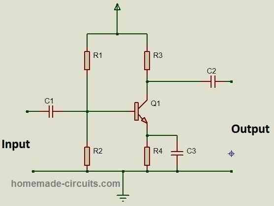
Referring to the circuit shown in Fig. 2, we can observe that the configuration using capacitors C1 --- C3, transistors Q1, Q2, and resistors R1-----R4 form a pink-noise generator circuit.
Transistor Q1 is hooked up like a reverse-biased diode junction, and is accustomed to crank out a white-noise (haphazard noise) signal.
That white noise signal is capacitively coupled to the base of Q2 through C1.
Transistor Q2 amplifies the noise signal. The Q2 output is applied to C2, for eliminating for for filtering out the higher frequencies so that it replicates pink noise far more strongly.
Parts C4, U1, U2, and R5-R14 are configured to form an audio amplifier/noise amplifier/mixer circuit respectively.
The noise generator output is adequately high for serving the intended functions and this only needs some buffering, that's all.
The filtered pink-noise signal is supplied by means of C3 and R5 to the inverting input of U1, which generates an boosted and an inverted replication of the input audio signal.
Op-amp U2, in association with resistors R12 and R8 are put together to provide a optimum gain of 100, getting rid of an extra preamp stage before the digitizer.
The output of U1 and U2 merge at the junction of R14 and C4, and are the finalized enhanced super digitized audio is supplied circuit's output jacks.
Construction
It is advised that you build the Digitized audio circuit over a PCB.
A PCB layout for the proposed enhanced digital music circuit is demonstrated in Fig. 3.
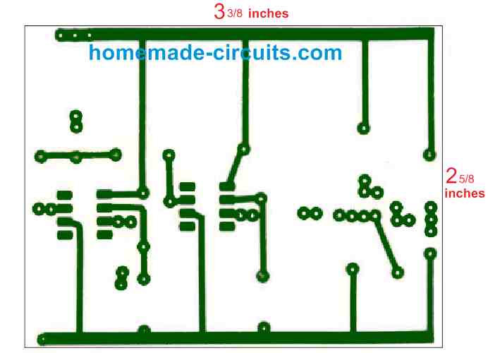
Once the pcb is etched out you may start procuring the parts, and then start the construction work.
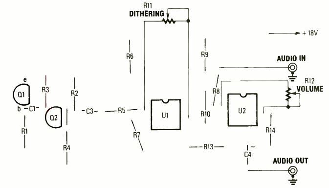
Begin by soldering the IC sockets around the areas as pointed out in Fig. 4. Next, assemble and solder all the components on the PCB accordingly.
Ensure that all components that have polarity are installed using the appropriate direction. You can incorporate RCA-type phono jacks for the audio input and output.
Power Supply
The only single important thing that you need to take care with this circuit is the power supply.
The power supply has to be specifically a regulated pure DC with absolutely zero ripple content. For this reason, we recommended using batteries for powering the circuit.
Considering that the output is a high-impedance output, a couple of 9 V batteries could simply go on for months, even if you do not incorporate a switch still the battery can probably last for many months.
Testing
Testing the dithered music enhancer circuit is actually pretty easy, since you simply do not need to calibrate anything here.
Initially, rotate the audio volume control (R12) completely to the minimum position and adjust the dithering control (R11) to the maximum limit.
If you analyze the audio output for the dithering, you will be able to detect a low-level of pink noise.
Now begin turning R11 down and move the R12 upward, insert an audio source into the AUDIO IN jack (J1) and analyze the output sampled audio.
You will be able to detect a sound which is simply the input audio without any enhanced dithering.
To enable the introduction of the dithering, rotate pot R12 to minimum and start tweaking R11 while the audio gets sampled.
Without any audio input, adjust the potentiometer R11 so that the sampling of the input audio jumps up and down through the center by 1 bit each way.
Next, adjust the potentiometer R12 until you find the audio reaching the most optimal amplitude.
Once these procedures are complete, you will be surprised to hear the final enhanced digital dithered music, which will appear a lot clearer, crisper, sharper and more "apparent".


Questions & Answers
This is the circuit . I hope this gets through to you.
Good day, thanks for this interesting topic. I was wondering what are you using as a A/D converter? Is it the LM741 working as an A/D converter? I’m confuse, cause I saw one day a circuit for A/D converter an it was a very difficult to found IC, so If I can built an A/D converter
using the LM741 it would be a very good thing!
Another, funny comment is how easy will we get an analogue audio signal in today’s world cause almost everything we use is digital audio.
I got covid-19 and was isolated for 10 days, now I’m back to work. Will email the query I will explain about the power supply soon.
I have made a simple circuit to time the engine run of a model airplane. Works great with some engines but not all because the engine cut-off is not always clean and the timer continues to run instead of stop. Maybe bouncing contacts of the relay or chatter of the waveform. Any solutions?
Sorry, can’t figure it out!
The first op amp works like an AD converter but it is not exactly an A/D converter since it only induces or mixes the noise element into the analogue audio….a real A/D converter would chop the analogue content into proportionately spaced PWMs, like in the following concept:
Class D Amplifier Circuit Using IC 555
All audio that we hear are actually analogue audio because a digital audio will also get converted to analogue by the speaker before reaching our ear…a pure digital would be full of distortion.