In the following post I have explained a simple yet enhanced 12V capacitive discharge ignition system which derives its operating voltage from the battery instead of the alternator for generating the igniting sparks.
Since it works independently from the alternator voltage, without depending on a pickup coil signal, it is able to function more efficiently and consistently, enabling a much smoother ride of the vehicle even at lower speeds.
Contact Breaker Vs CDI
A capacitive discharge ignition unit also called the CDI unit is the modern alternative for the age old contact breakers, which were quite crude with their functions and reliability.
The modern CDI is an electronic version of the contact breaker which uses sophisticated electronic parts for generating the required arching across the spark plug terminals.
The concept is not complicated at all, the section of the alternator provides the required 100 to 200V AC to the CDI circuit, where the voltage is intermittently stored and discharged by a high voltage capacitor through a few rectifying diodes.
These rapid bursts of high voltage discharges are dumped into the primary winding of an ignition coil where its appropriately stepped up to many thousands of volts for acquiring the required arcing, which ultimately functions as the igniting sparks across the connected spark plug contacts.
I have already discussed the basic electronic CDI circuit in one of my previous posts, though the circuit is extremely versatile, it depends and derives its operating voltage from the alternator. Since the alternator voltage depends on the engine speeds, the generated voltages tend to get affected with varying speeds.
At higher speeds it works fine, but at lower speeds, the alternator voltage also lowers, this results in an inconsistent sparking forcing the alternator and the engine to stutter.
This inconsistency ultimately affects the functioning of the CDI and the whole system starts getting hampered, sometimes even causing the engine to halt.
The circuit of an enhanced capacitive discharge ignition circuit which is discussed here, eliminates the use of the alternator voltage for functioning, instead it utilizes the battery voltage for generating the required actions.
The Circuit Concept
The whole concept for this electronic CDI can be understood by studying the shown circuit diagram below:
The diodes, the SCR and the associated components form a standard CDI circuit.
The high voltage of around 200V which needs to be fed to the above circuit is generated through an ordinary step down transformer connected the other way round.
The secondary winding of the transformer now becomes the primary and vice versa.
The low voltage primary winding is fed with high current pulsating DC generated by a standard IC555 circuit via a power transistor.
This pulsating voltage is stepped up to the required 200V and becomes the operating voltage for the attached CDI circuit.
The CDI circuit converts this 200V into bursts of high current for feeding the input winding of the ignition coil.
These rapid high current bursts are further amplified to many thousands of volts by the ignition coil and finally fed to the connected spark plug for the required arcing and the initiating the ignition of the vehicle.
As can be seen the input voltage is acquired from a 12V DC source which is actually the battery of the vehicle.
Due to this the generated sparks are very consistent without interruptions providing the vehicle a constant supply of the required ignition sparks irrespective of the vehicle situation.
The consistent sparking also makes the fuel consumption efficient, makes the engine less prone to wear and tear and enhances the overall mileage of the vehicle.
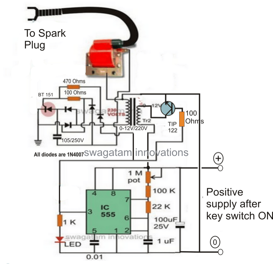
Use a 1K resistor at the base of TIP122...... 100 ohm is incorrectly shown
Synchronizing with Wheel RPM
If you want the above circuit to be triggered by the alternator so that the combustion is ideally efficient and synchronized with the wheel RPM, the above design may be modified in the following way:
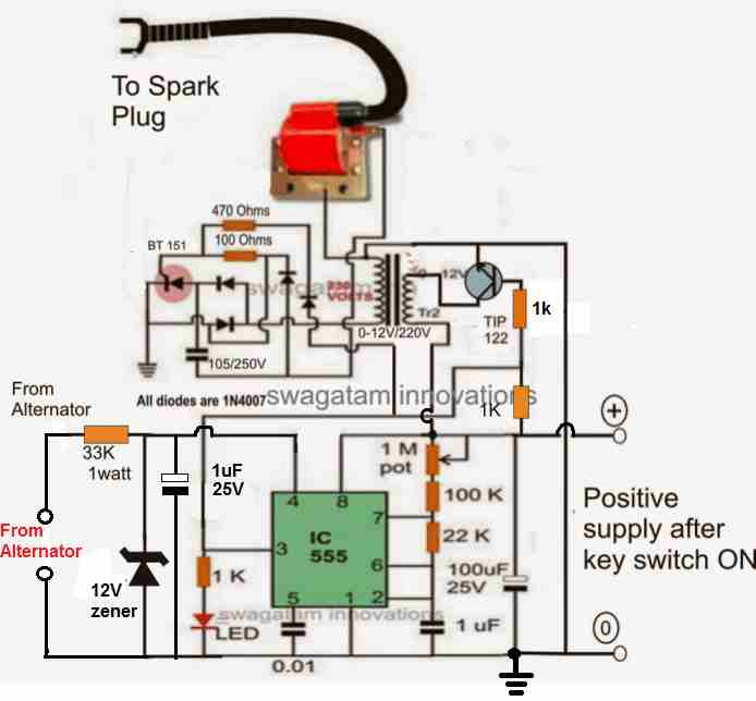
A 1K resistor is used at the base of TIP122...... since 100 ohm is incorrectly shown.
The above configuration may be further modified as shown in the following diagram, which appears to be the most appropriate way of implementing the proposed enhanced CDI circuit for all 2 and 3 wheelers.
How it Works
As we know, the reset pin#4 of IC 555 requires a positive potential to allow the normal functioning of the IC 555 as an astable or as monostable. If the pin#4 is not associated with the positive line, the IC remains dormant and disabled.
Here the pin#4 of the IC can be seen connected with the alternator voltage. This voltage can be of any level from the alternator, it doesn't matter, since it is appropriately stabilized by the 33 k resistor and the following zener diode, capacitor network.
The alternator will generate a positive and negative cycle pulses, in response to each rotation of the vehicle wheel.
The positive pulse will be converted into a 12 V positive feed at the pin#4 which will cause the circuit to initiate and stay activated during the entire positive pulse duration cycle of the waveform.
During these periods, the IC 555 will operate and fire the SCR multiple number if times in short bursts, causing the ignition to fire with higher efficiency and for a sustained period of time during the firing angle of the combustion and the piston.
This will also enable the CDI to work in tandem with the wheel rotation generating an ideally synchronized combustion of the engine and with an optimal efficiency.
Finalized Enhanced CDI Design with PWM Control
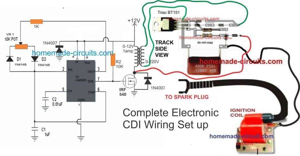
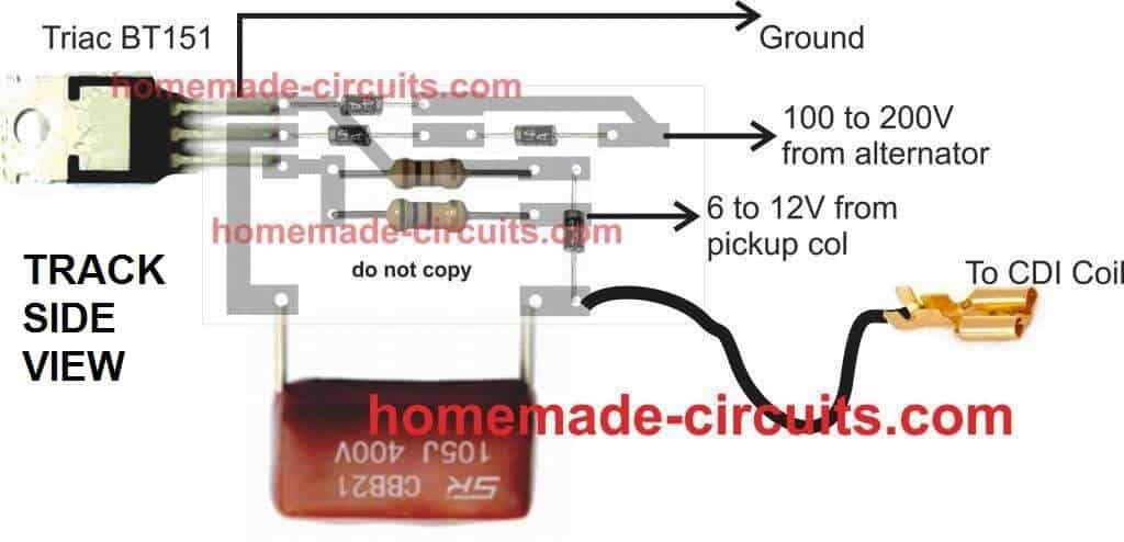
CDI PCB Circuit
Parts List
All resistors are 1/4w unless stated
1K - 1
10K- 1
POT 10K - 1
100 Ohms 1/2 watt - 1
56 Ohms 1/2 watt - 1
Diodes 1N4007 - 9
Capacitors
1uF/25V - 1
0.01uF/50V Ceramic - 1
105/400V PPC - 1
Semiconductors
IC 555 - 1
Mosfet IRF540 - 1
SCR - BT151
Transformer 0-12V/220V/1amp - 1
CDI ignition coil - 1
Video Clip showing the Test Result of the above shown electronic capacitive discharge circuit system
Another Version of Electronic Ignition
The following diagram provides another version of a IC 555 based electronic ignition system, which I got from an old magazine page:
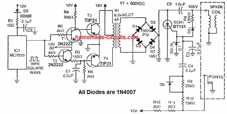
Here, the left side stage which includes the IC 555, 4 transistors and the X1 transformer, form a 12 V to 500 V step up push pull inverter.
The right side section using the SCR BT151, and the associated circuitry forms the capacitive discharge ignition stage.
The design works with the old contact breaker type of mechanism, for timing the ignition and triggering the SCR.
While the contact beaker remains closed, the SCR remains disabled, and this allows the capacitor C2 to charge via the 500 V DC from the inverter output. Next, as soon as the contact breaker opens, the SCR gets its gate trigger via R9, 10, 11, 12, and C4, and it fires causing C2 to discharge across the attached ignition coil primary winding, which in turn causes the secondary of the ignition coil to produce the required high voltage pulse into the spark plug for the required ignition.
With Pickup Trigger
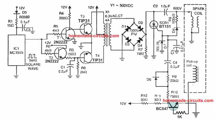
In modern vehicles we find the contact breaker being replaced with a pickup coil, which ensures a solid state working of the system without any wear and tear. The above electronic CDI design could be also used with pickup coil set up, with the following given modifications.



Questions & Answers
Hi Swagatam,
How is the coil triggered? Is this done by completing the ground after the BT101?
Thanks in advance,
Matt
Hi Matthew,
Yes that's right, it's when the SCR triggers….. the capacitor discharges via the ign coil.
Hi Swagatam
A regular 220v/12v-1A transformer would be quite large if we consider the size of genuine CDI units. Can we shrink the size of the transformer, like using a toroidal core? Or some other method?
Hi Abu-Hafss,
Yes that's true, very soon I would possibly post an identical article with a ferrite core transformer.
Shall be waiting…..
Hello Ustaad Jee
Normally, the two wheelers have 6V batteries. In that case won't the need to be 220v/6v? What would be the amperes?
Hello Guruji,
Can you specify which two wheeler today uses 6V? I have never seen one.
But anyway, yes the trafo primary V rating would depend and should match the battery voltage.
Hmm, perhaps you are right. Actually, I never owned/driven a bike, only car. Earlier, the bikes had 6v batteries and I assumed they are still having the same set-up. Thanks for the up-date.
By the way, just for learning sake, if it is 6V system what should be the amperes?
lower volts would mean higher current requirement for lights, horns etc that's why 12V batts are preferred instead of 6V today.
Current isn't much of an issue here because the spark plug gap is so small that even a 500mA trafo would work nicely.
Recently I posted another related circuit here:
https://www.homemade-circuits.com/2013/10/universal-multi-spark-enhanced-cdi.html
Hi Swagatam
As discussed in an earlier post under the 555-12V BOOST CIRCUIT, I integrated that circuit with the CDI circuit.
The output shown on the left is the one without the boost circuit having AC input from the two-wheeler itself.
The one on the right is with the AC supply from the boost circuit. As mentioned earlier, the supply is about 220VAC varying between 0-220V. It could not be rectified. As per your suggestion, adding another 10uF capacitor drops the voltage to 160V.
You can see the difference between the two outputs. The points at which the voltages were recorded are marked in the circuit. In the left circuit you can see there is constant rectified 200VDC. The response to the trigger can also be noted. Whereas, in the right circuit the voltage is not rectified.
Any suggestion?
Still waiting for the CDI with ferrite core transformer, which you proposed on Oct. 11, 2013.
Thanks Abu-Hafss,
I'll look into it and reply you as soon as I figure out a suggestion.
Hi Abu-Hafss,
Can you please isolate the the CDI and the 555 boost circuit and then perhaps confirm the voltage waveform of the 555 stage? This would help us to know the origin of the negative pulses, if it was from the boost circuit or the CDI coil?
Also the bjt stage could be removed (as it looks immaterial) and a 1N5402 added parallel to the 10uF cap in the boost circuit
Here's the link of the proposed ferrite core cdi circuit:
https://www.homemade-circuits.com/2013/10/universal-multi-spark-enhanced-cdi.html
Actually it should be "ignition coil", wrongly written as trigger coil.
The ignition coil would be already present in the vehicle, it will need to be integrated with the assembled circuit as given
hi sir can u please tell me if this cdi ignition circuit can be used in old point ignition enfield bullet and how i can wire it because a pair of wire coming from alternator to point then capacitor.please elaborate it with diagram for bullet with point ignition.
Hi Arindam, a modern cdi circuit can be replaced with all types of previous contact breaker type of cdis.
I am not very sure about their wiring, I think it would be better to consult an auto electrician, he would be able to provide the right solution.
Nice CDI Man!!!
How is it triggered???? Is a Piggy back design? it would produce a capacitive spark each time the original vehicle inductive fires???
It would be nice having the two sparks (original inductive and added CD) working together. Original inductive long lasting and CD high peak…
Regards
Thanks Athal,
Please see the second diagram, you can trigger it through the alternator by connecting the ICs reset input with the alternator pulses.
The number of sparks per alternator pulse can be adjusted by the setting up the 1M ppreset accordingly
Dear Swagatam,
I was speaking about the DC 12v battery powered scheme (not the AC from alternator). The scheme shows the DC 12V + and – conexions but I can't see the triggering input. Because of this I was wondering if this unit Works as a piggyback of an inductive OEM system (negative is also triggering). Having both inductive and capacitive spark discharging simultaneously (using HV diodes to protect inductive circuit) would be great (like MSD Stacker or Pertronix second strike).
Again: nice Project!
Where can i download any PCB drawing an list of components?
Thank you.
Dear Athal, it's triggered via the pin3 of IC555 through the 470 ohm resistor into the gate of the SCR.
The 555 IC output at pin3 does a dual job of creating the 220V AC for feeding the capacitor as well as triggering the SCR for the required discharge sparks.
Sorry, PCB design is not available as it would be quite time consuming for me to design, your PCB maker would do it very easily.
The parts can be easily noted down from the diagram itself, just click on the diagram to enlarge it. All the components are standard, resistors are 1/4watt 5% CFR
Dear Athal
The triggering should sync with TDC position of the piston. For that particular reason the motorcylces' flywheel are equipped with a small raised metal strip and pick-up coil is installed at a position that it sync with the TDC of piston. Thus the triggering frequency is directly proportional to the RPM.
However, in the captioned circuit the 555 will trigger the sparks at a constant frequency, irrelevant of TDC position. I cannot simulate how this circuit will behave when installed. Please do share your practical experience.
Thanks & regards.
Thank you Abu-Hafss!!
Dear sir,
This circuit can be use for 2 stroke motocycle (150cc)?
Is it making spark plug longer life time and bigger spark?
thanks
Dear nuraniku,
yes it can be used for 2 stroke engines, and will create more efficient sparks than traditional CDIs
Dear Sir,
This circuit can be use for small mist blower?
can't say, have no idea about it.
thanks
Hello Swagatam, I have been following this blog for quite sometime now and very impressed for your unending and unselfish support for those who are in need. Great job.
I have an HHO installed on my motorbike and I need to retard the spark timing. I plan to build your enhanced CDI with a spark timing adjustment incorporated in it.
Please advise. Cheers!
Thanks Edgar, sure! you can try retarding the sparks by employing the spark control facility provided in the enhanced version of the CDI circuit
Best Regards.
Hi Swagatam, thanks and appreciate your prompt reply. In both circuits above, the 12v input trigger pulse from the alternator is not indicated. I believe, it is to pin#2? Regards!
Hi Edgar, the second circuit actually includes the feature, please see on the left of the circuit (pin4 of the IC)
Hello Swagatam, is the trigger pulse from the alternator AC? If so, need to rectify it before pin#4? Thanks again.
oops, sorry, didn't notice the zener diode… please disregard & delete previous inquiry. Thanks again.
Hello Edgar, the input at pin4 should be actually from the trigger coil of the alternator, yes the zener diode will make sure that the signals are appropriately stabilized before it reaches the IC.
Hi there Swagatam, I plan to retain my existing motorbike cdi and instead insert and adjustable spark delay circuit still triggered by the alternator pulse signal. Hence, driver must accommodate 100vac+ fast switching? Is there a mosfet for ac switching? Or, the other way around, can the existing OEM CDI accept a dc pulse? Thanks again, friend!
Hi Edgar, you can probably do it by isolating its existing trigger input and integrating it with a 555 astable input as shown in the second design above.
The 555 circuit could be powered from the 100V source itself after stepping it down and rectifying into a clean DC through a capacitive power supply.
move the scr to the secondary side so we can trigger when we need spark, leave the 555 pulsing the primary keeping the cap charged, this circuit will not work its sparking all the time
sorry, No! the above circuit must be built just as shown, I have tested and verified the design practically.
How can it spark all the time when pin4 of the IC is connected with the trigger signal??
hi bro,
what is the difference between the alternator ang magneto,rectifier?
both are electricity generators, "alternator" is derived from alternating current which forms its output while "magneto" is from the magnets involved in generators for generating electricity.
Tiaki Senior has a point. Your circuit is sparking all the time, there is no way of triggering it to coincide with the position of the piston. It may work, but will fire much too early for low rpm at tickover.
the second circuit is not sparking all the time, it's synchronized with the alternator through its pin4…. I hope you know how IC 555 works.
maybe its the terminology been used thats making it confusing , as the alternator does not provide timing , the trigger coil does for cdi , in cdi circuts the cap is always charged with stator then the scr is triggered when needed, the circuit above looks like the 555 astable output goes to the scr and the 12v coil, so looks like even if i triggered it at the correct time it has to charge the cap and trigger the scr at the same time? but wondering does the scr turn off when the 555 output goes low?
the scr will surely turn off due to absence of the gate trigger and also the 200v charge voltage from the transformer….only during the short trigger periods from the alternator the SCR will get the chance to fire may be in the form of bursts of multiple sparks….
the main intention here is to make the scr fire the capacitor through multiple sparks even after the transformer is been switched OFF, but it seems the present circuit is not designed to do this.
the circuit could be modified to do this by including a small value capacitor across the junction of the gate 470 ohm resistor and the diode cathode…this will allow the scr to be in the firing mode for a few millisecond more until the high voltage capacitor is completely discharged for every trigger pulse from the alternator.
at 1000rpm on a single cylinder 2 stroke, sparks every 16 seconds, which is already faster than the astable output making the 555 circuit useless , isnt the scr and tip122 just going to stay on because the r/c timing for the 555 never going to discharge fast enough to go low, run the 555 separately in astable just fot the charge circuit for the cap , trigger the scr directly, then the circuit would work fine, forget multispark with scr arrangement.
without multi-spark feature the whole purpose of the design would become meaningless and it would become as good as an ordinary CDI as given here:
https://www.homemade-circuits.com/2011/12/how-to-make-capacitive-discharge.html
meaningless when the circuit doesn't work for a engine which it was intended, the advantage with your circuit is that it creates high voltage for the coil, which would make any engine start way better. your description doesn't explain that where trying to achieve multi spark cdi anyway
actually all CDIs are designed to generate high voltages with the help of the available 100-200V from the alternator, the advantage of the above circuit is that it does not rely on the alternator voltage which could fluctuate with engine speeds making the procedures inefficient, rather the circuit makes use of the battery voltage for supplying a consistent power to the ignition system.
the second circuit was designed by me after some research and suggestions from the readers and later on I realized that the design could be well modified for generating multiple sparks which was a bonus to the existing design.
The 555 signal allow the capacitor to get discharged through multiple sparks by breaking the charge into many pieces instead of dumping the entire voltage instantly as we have in ordinary CDIs. This perhaps helps to produce a smoother transition to the engine speeds and combustion.
However the second circuit needs slight modifications, I'll hopefully do it soon.
clearly you have no idea how a piston engine works or cdi's in general , a cdi that uses' the stator for for high voltage do not generate any high voltage at all, the scr just passes the already high voltage from the cap which got charged from the from the stator to the igniton coil.
look at your first circuit , it continuously sparks from power on, EPIC FAIL!!
second circuit i have already outlined the problems which you are not grasping.
rename the circuit head title to "Jacobs ladder" that's what you really designed a CDI it is not.
i have told you how to fix it , you don't listen so take it on the chin.