In this post I have explained how to assemble IC 555 for generating interesting LED circuits with blinking, flashing and fading light effects with some minor modification and enhancements.
Why use an IC 555 Astable
The astable multivibrator mode is the most fundamental mode of operation of the IC 555. In this mode it basically functions like a free running oscillator. If this oscillator rate is reduced sufficiently, can be used for driving LED lights.
The wiring at the output can also be further modified for achieving interesting variations and light illumination patterns over the connected LED.
Some of the practical ways of this is explained here, circuits diagrams of LED flasher, ghost effect generator, alternate blinker, light fader etc are also included.
In this article I have explained a few interesting and simple LED blinker circuit configurations using the ubiquitous IC 555.
The basic flashing mode has been kept intact yet various different attributions are provided to the circuit with its flashing rate and pattern.
The IC 555 is a complete package for the hobbyists. You can build numerous interesting circuits with this chip and make it to work as virtually any way you desire.
Though the circuit provides us with many application ranges, flashers configurations are more commonly associated with these chips.
These can be made to blink all types of lights at different rates depending upon individual preferences.
You can flash LEDs, torch bulbs, string lights or even mains AC lamps with circuits incorporating this IC.
Basically, to configure the IC as a flasher or blinker, it’s connected with its fundamental astable mutivibrator mode.
This configuration in fact requires just a couple of resistors and a couple capacitors to kick start the said functions.
Once the chip is assembled as an astable, we can go ahead and enhance the output in many different ways to get outstanding visual treats.
Let’s learn how a few fabulous IC 555 circuits with LED can be built with the following discussions, but first we would like to know what materials are needed for this.
Being a hobbyist you would want to have a bunch of assorted resistors in your box of goodies and also some selected values of capacitors.
For the present projects you would require a handful of different value resistors and capacitors.
Parts List for the proposed flasher and fader circuit using IC 555
- Resistors rated at ¼ watt, 5 %, unless otherwise stated.
- Resistors – 1 K, 10 K, 680 Ω, 4.7 K, 100 Ω, 820 Ω, 1 M etc. = 1 each
- Capacitors – 0.01 µF, 470 µF, 220 µF, 1 µF = 1 each
- Zener diode – 5.1 volts, 400 mW = 1
- LEDs – Red, Green, Yellow 5mm
- IC 555 = 1
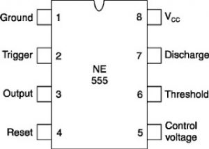
IC 555 Pinouts
Video Demo
Creating Flashing and Fading LED Effects using IC 555 Circuit
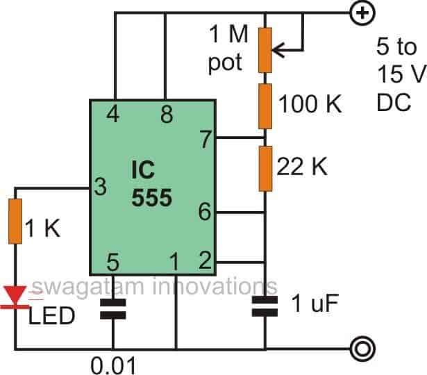
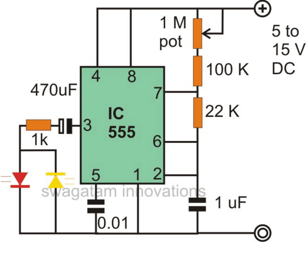
The first figure shows the basic configuration associated with a 555 IC LED circuit. Here it is connected as an astable multivibrator.
The resistors and the capacitor 1 uF can be experimented with to get different rates of blinking over the connected LED.
The LEDs can also be used with other colors.
The 1 K resistor can be replaced with lower values for increasing the intensity of the LED, however it should not be reduced below 330 Ohms.
Alternatively the 1 M resistor can be interchanged with a pot for attributing the circuit with variable blinking rate feature.
Making a Police Revolving Light Effect
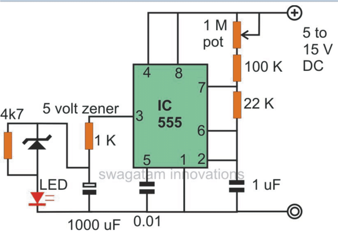
The above circuit can be suitably modified for producing a revolving, flashing police light effect to the above constructed circuit.
Here by adding a network of a zener diode / resistor / capacitor, to the output of the circuit, just as shown in the figure, we can acquire a very peculiar effect with the generated illuminations of the LED.
The LED initially glows bright, then slowly dies down, but intermittently gives a high intensity pulse producing the discussed police warning roof light indicator illusion.
Random Light Effect Generator Circuit
The 555 LED configuration shown in this figure enables us to use the circuit to generate random light patterns over the connected group of LEDs.
As shown, three LEDs are connected in conjunction with a couple of resistors and a capacitor.
The two LEDs connected in parallel but with opposite polarity, flash alternately at a particular rhythm while the third LED fluctuates at some other random rate.
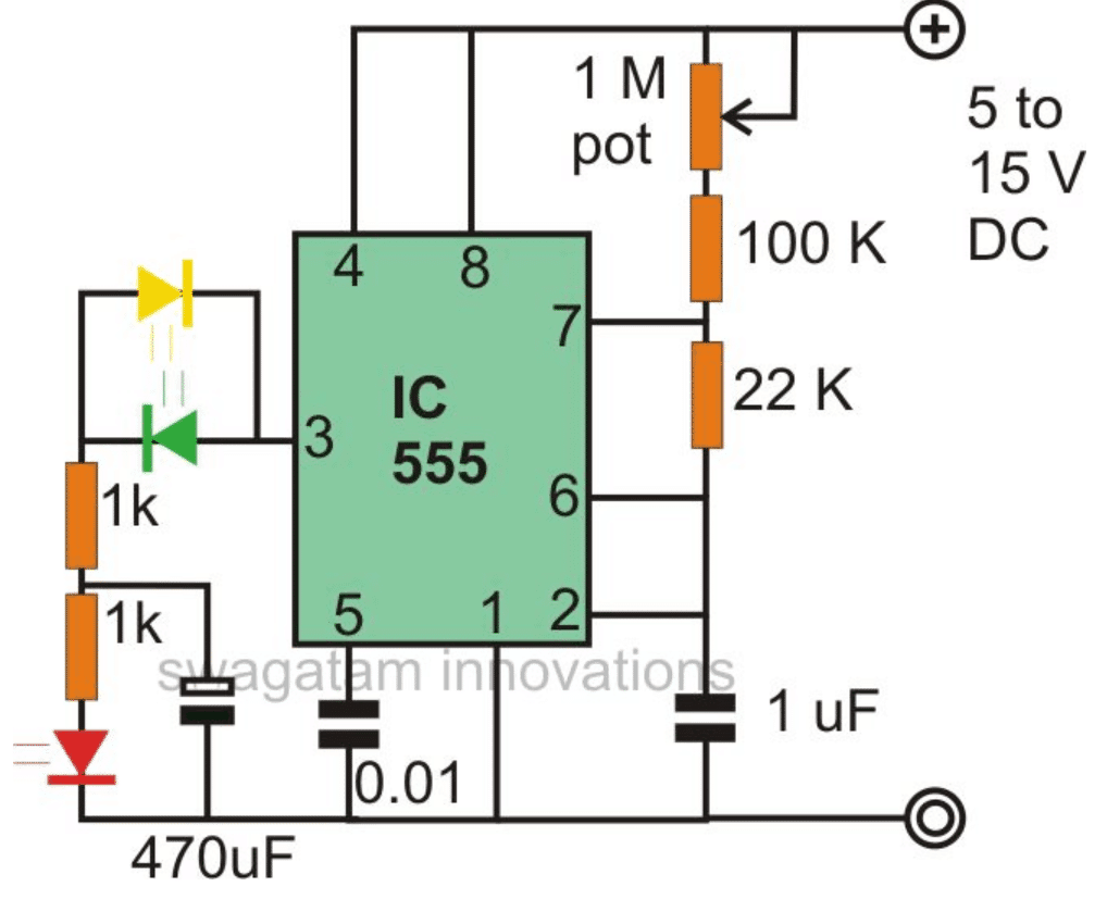
The above effect can be simplified by the circuit shown below.
Here, the LED which is connected to the 1 K resistor blinks at the fixed blinking rate, but the next LED which is connected to the ground switches rapidly at some other defined rate.
Adding a Spooky Effect to the LED
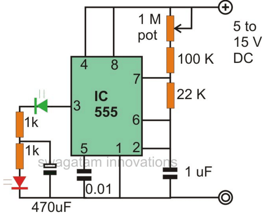
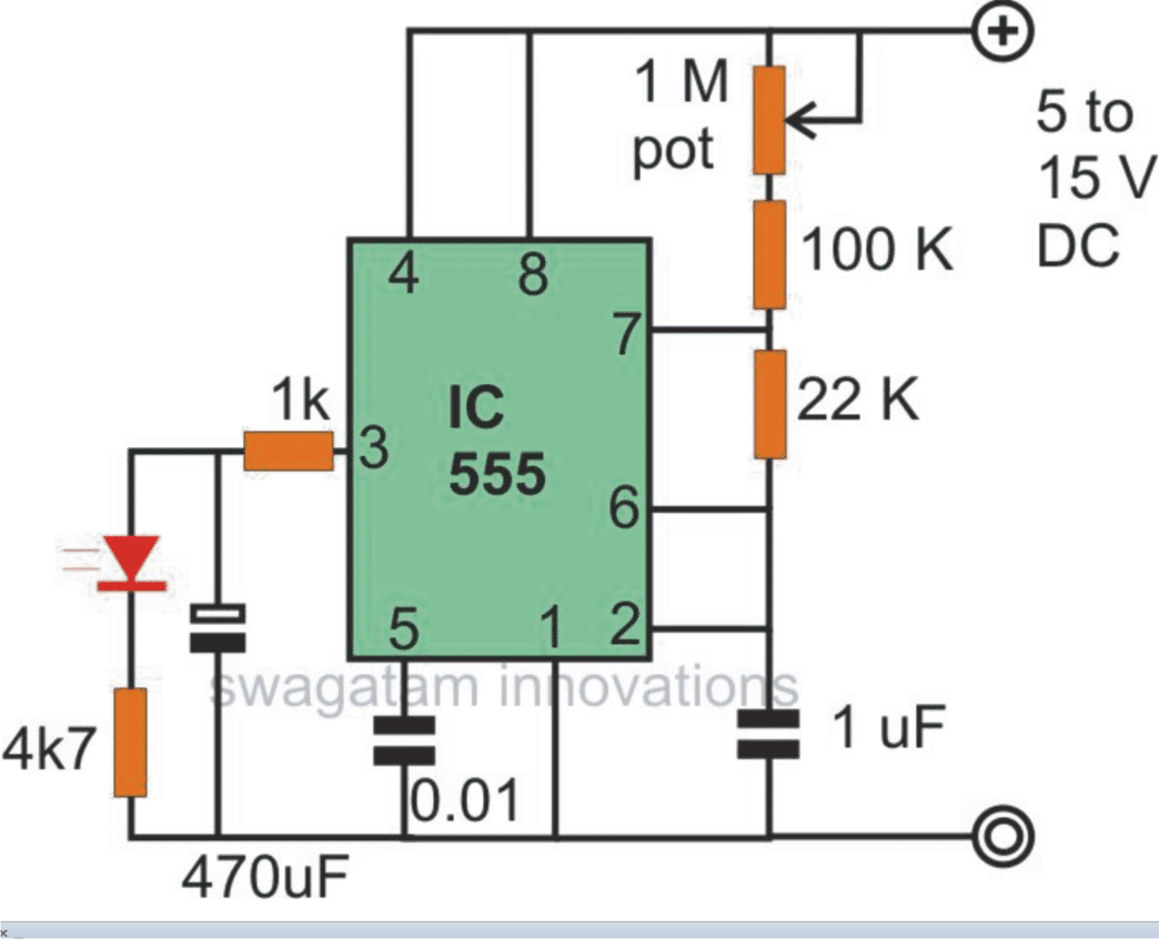
If you want to produce some strange illumination pattern over the LED discussed through the above circuits, them it can be simply done using just a couple of resistors at the output of the IC.
As can be seen in the figure, two resistors and a single resistor are connected at the output of the IC in a special way.
The network switches ON the LED sharply, but switches it OFF slowly, producing quite a creepy visual effect.
Alternate Flasher Circuit
This IC 555 LED circuit configuration is pretty straightforward, as we all know; two LEDs can be connected to the IC output for generating an alternate blinking pattern over the connected LEDs.
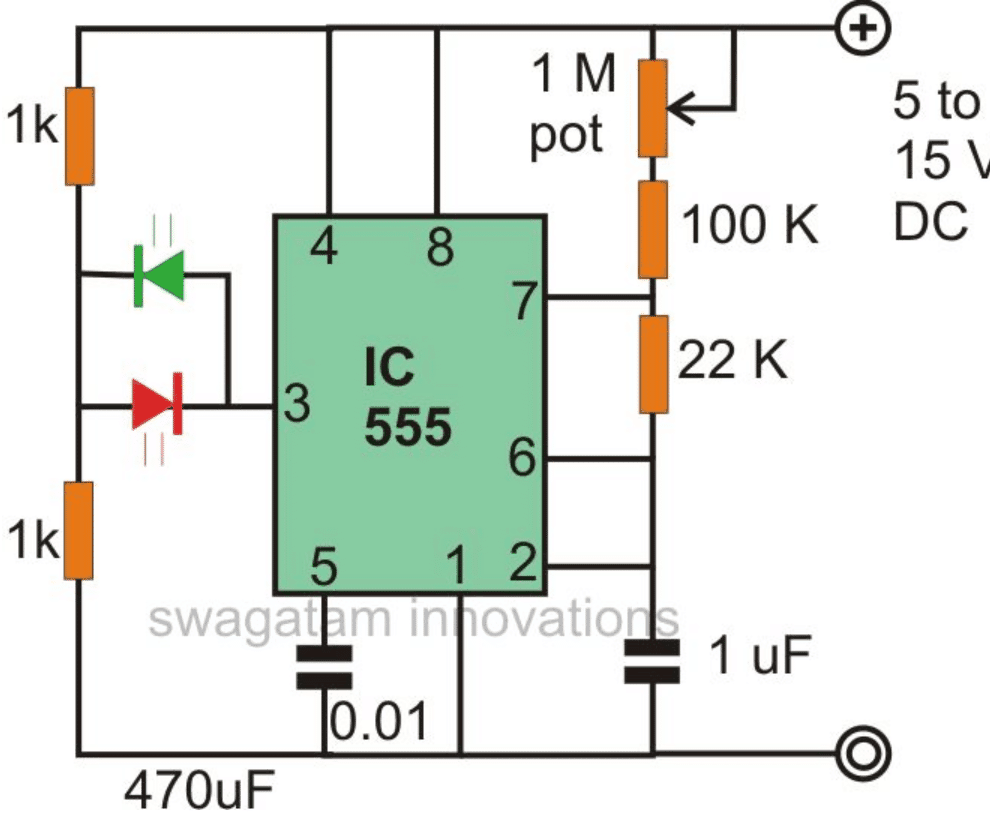
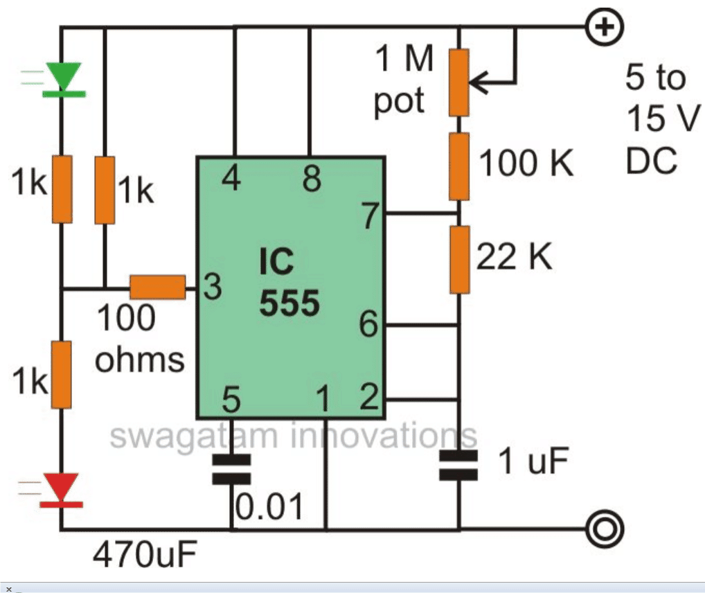
The above circuit can be further modified as shown below by complely disarranging the network with the shown type.
Here the LEDs though blink alternately, the intensity may fluctuate from dim to bright over the LEDs.
Light Fader Circuit Using IC 555
A very interesting light fading effect can be achieved by wiring up the IC 555 circuit as per the diagram shown below.
The circuit switches ON the LED very gradually and does the same while switching it OFF, that is instead of shutting it off abruptly, does it very slowly.
555 Strobe Light Circuit
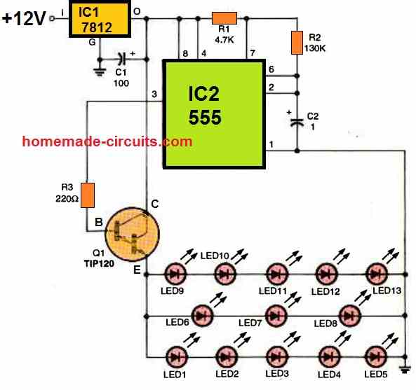
The next 555 LED circuit depicts a schematic design of the strobed-LED lighting system, which is based on a pair of commonly accessible integrated circuits (IC1, an LM7812 fixed 12 volt regulator, and IC2, a 555 oscillator/timer).
It is necessary to calculate the optimal duty cycle and frequency for the oscillator (IC2).
In other words, we're trying to perfect it when it comes to optimal frequency and duty cycle.
The circuit is set to run at a frequency of 3 Hz with a duty cycle of 50%. The operating frequency of this 555 strobe light circuit was determined with the help of a handy 1 uF capacitor C2 connected between pin6/2 and ground of the 555 timer/oscillator.
The 555 output (pin 3) is linked to the base of Q1, a TIP120 NPN Darlington transistor. The transistor, works like a switch and switches current to cause a strobing effect on the LED lighting module in response to the oscillator output (555 IC2).
Another Strobe Light Circuit using Two IC 555
The captivating strobe light circuit showcased below was generously shared by one of our dedicated blog readers, Mr. Vee.
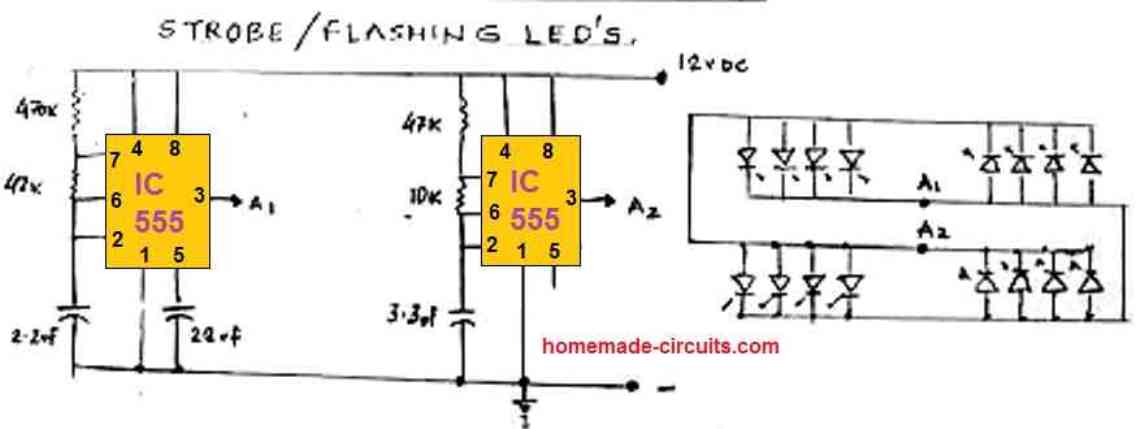
This design employs two IC 555 astable circuits, each operating at slightly distinct flash rates, resulting in a fascinating alternating strobe light effect across two sets of LEDs.
This striking LED strobing pattern not only captures attention but can also serve various purposes, including advertising displays, warning signal devices. It can be also used for automobile applications, for example as a car reverse alert lamp flasher, where the strobing LEDs warn the users regarding the reversing car.
Video Demonstration
555 Firefly Light Flash Simulator Circuit
It's not always the most elegant method to use a flashlight to attract fireflies for summertime evening entertainment with the kids.
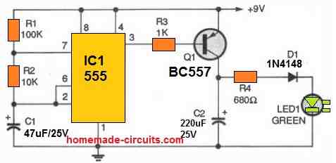
This straightforward circuit comes in handy by more accurately simulating a firefly flash in terms of color, attack and decay times, brightness, and frequency.
Our 555 LED firefly circuit is customizable to mimic the flashing attributes of any of the 125 varieties of fireflies prevalent across the country, seems to last eternally, avoids damp soil, will not really eat bugs (but uses electrons provided by a 9-volt battery).
R1, R2, and C1 control the timing of a 555 timer, which produces a 0.25 Hz, high duty cycle square wave.
A low duty-cycle signal is produced by inverting the output using the PNP transistor. The green LED's green luminous intensity slowly fades as the 220 uF capacitor discharges via the 680 ohm resistor (R4) and capacitor (C2).
An electric firefly that shines every four seconds is the final outcome. The green flash has distinct attack and decay characteristics and can last for around half a second.


Questions & Answers
Hi, I wonder if the 555 would work with a 3.7v battery. I want a few leds in my son's helmet, and it would be nice feed them with an old cell phone battery. Thank you!
The minimum operating voltage for 555 IC is 4.5V, so I am afraid it wouldn't work. You can try any one of the designs given in the link below, it would give you the intended results. You can replace the pots with some fixed value resistors, and use LEDs on both the arms of the transistor collector.
https://www.homemade-circuits.com/2012/01/how-to-make-any-light-strobe-light.html
Hi swagatam bro….i saw ur blogs….i need ue help to do a bus running light by using around 300 led….how i make that ……plz help me…….
Hi Jagdish,
Can you pls provide some more details about the requirement.
The above circuits will only blink a single LED ON/OFF, while a chaser circuit will create a running effect over 10 separate LEDs connected at the relevant IC outputs, that's the difference.
show me the video link…
http://www.youtube.com/watch?v=J964lGezvMk and are http://www.youtube.com/watch?v=HKaHRosvm80 are the videos in the second link from 0.15 to 0.20 sec and 0.35 to 0.39 sec are the required speed variations and the power of the red leds must be great ……..like the one you have used it for knight rider project of yours.
Thanks ,
2308cars.
It looks like a strobe light kind of circuit, you can try the following circuit…….use high bright RED LEDs for all the channels shown:
https://www.homemade-circuits.com/2011/12/simple-yet-effective-led-strobe-light.html
Sir ,
I want the effect like stobe not chasing one .this video will help you out more in the given below video the flasher blinking rate desired is from 0,01 sec to 0.06 sec in the video .
: m.youtube.com/watch?v=JhoxkxbRZXo
Thanks ,
2308cars
Hi Shreyas,
You can try the first circuit on this page, replace the 1M pot with a fixed 1M resistor, remove the 100k resistor and replace the 22k resistor with a 22k pot.
First confirm with a single led as given, by the varying the 22k pot, and if it satisfies your requirement you can increase the number of LEDs as desired.
I was wondering what is the circuit used by multi mode led trail light designers. It's it possible to change the rate of blinking, enabling constant on, etc by pressing the same button more than once. I've thought about it but am not able to understand how they make it.
it will require a microprocessor, cannot be done using ordinary ICs.
Hi Mr. Swag,
I want to build a flasher with about 200 LEDs using 9 volts or 6 volts transformer, the circuit I built with 555 IC was not able to power the LEDs.
Please help out with a circuit digram or instruction on how to go with this project.
Thank you.
Hi Mr. Ethelethoh,
Please refer to the first diagram in the following link, see how the leds are wired up. You can connect as many led strings you want in the shown manner. The resistor will need to be calculated appropriately depending on the wattage of the LEds:
https://www.homemade-circuits.com/2012/10/automatic-40-watt-led-solar-street_2.html
evening, just tried to make the Police Revolving Light Effect, but no luck. if I disconnect pin 1 the led will power up and the discharge slowly when the battery unplugged. any idea what I done incorrectly.
thanks
Tim
the circuit should produce a fading effect initially basically, can you tell me what are you expecting the effect to be, because there are number of different ways of implementing a particular desired feature
In the first circuit, can I use 33k instead of 22k??
yes can be used
hey i tried this circuit 4.bp.blogspot.com/-hHPYfQqo2RA/TvHQgoTZ6DI/AAAAAAAAAeE/Il07ySI-fmQ/s1600/555-5.png of yours alternative flashing circuit and it came very good. i tried connecting two 12v bulb of my bike but it didnt worked..please gie me idea to connect 12v bulb and battery 12v bike battery..also please say what component i have to change to increase the output volt and watt please…
p.s please reply to this post as i havent activated notify me on my previous comment sorry
Hi, do the following steps:
buy two TIP122 transistors. remove the LEDs and the 1k resistors from the existing design at pin3 of the IC
now connect the base of one transistor to pin3 via 1k resistor, connect the base of the second TIP122 to the collector of the first TIP122 via another 1k resistor.
join the emitters of the TIP122 and connect them with ground.
now connect the two bulbs across the collector and positive of the two TIP122s, meaning one wire of the bulb will join with the collector, the other wire with the positive…
do the same with the other bulb and the other transistor.
will try soon bro if i follow this i should able to glow 12v bulb ryt thankq 🙂 and will it the same for 24v?
yes 12V 1amp bulbs can be illuminated, 24bulbs will also work, but the IC circuit will need to be fed through a 7812 IC so that it gets a constant 12V.
hey frnd i built the above circuit without tip122 and it runs good when connected to 9v battery but if i connect the same to nokia mobile charger it blinks differently do mobile charger will produce high volt or watt than 9v battery?and what is the use of tip122??please 🙂
the flashing will depend on the input voltage, amps and the load amp, if these are not calculated properly would resulty in different flash rates for diffetent supplly sources.
TIP122 is for amplifying current.
thankq :))
hi frnd…i saw the LDR circuit in your blog..can i use this in flashing circuit?if so should i replace the LDR with the ON/Off switch?also what resistor i need to use?
Hi friend, which circuit are you referring to? please give me the link.
sorry coudnt find it :PP please let me know where to place this LDR in the flashing circuit,so that it turns automatically if it is too dark..i tried to replace with the switch but the light is off in dark and light turns on when light is falling into LDR (oppositely to my need) :PP in the alternate flashing circuit…also please specify which resistor i need to use to make led glow on an 24v….
disconnect pin4 of the IC from the positive line and connect it back through a 100k resistor to the positive.
now connect the LDR across pin4 and ground, this will hopefully produce the results that you want.
with 24V suply you will need a 7812 IC, use this IC to supply 12V to the IC555 circuit, the LEDs will work normally
thnkq 4 ur kind reply..will try the circuit with LDR for 24v today inbetween can i replace 100k into 100k pot? and will 7812 can able to manage approx29v? also please tell me best transistor than bc574. tried 2n2222 but the output is low comparatively..i am expecting an transistor to handle approx 29v and output gain shoul also be high..:)
we already have a 1M pot, so the 100k resistor should be a fixed type.
BC547 is rated to handle upto 45V, so it can be used
7812 will comfortably handle 29V input, the max tolerable input not to exceed 35V
thankz bro :))
i tried connecting ldr as you said but one led is glowing when light falls on the ldr..if the place is dark it works normal…how to stop glowing that led too??i tried using variable resistor of 200k but no use:Pso how to connect to rectify it? and how much volt does 200k variable resistor or preset can able to withstand??
Restore the pin4 connection to its previous form and use another 555 IC with the LDR as given in the last diagram of the following link:
https://www.homemade-circuits.com/2012/01/how-to-make-light-activated-day-night.html
In the diagram Swap R1 and LDR positions, remove the relay and connect the flasher circuit's positive to pin3 of the IC, meaning the supply to the flasher circuit will be now received from pin3 of the new 555 circuit not fr the battery.
will try it soon 🙂 inbetween i am going to connect 1k pot,6 double color led 25ma 3.2v each to a 24v circuit will it works good?or i have to add some other extra?
yes it will work, but not sure where will you connect the 1k pot?
1k pot beween +ve of battery and bulb which is connected in series..
use a 1k fixed resistor also in series with the pot for safeguarding the LEDs, i guess you are using it for dimming purpose?
no i used pot to adjust the input current is it enough or to add ik? since 6*3.5 needs 21v and have to reduce 8v and resistor calculator said 460ohms so only decided to put 1k pot…shall i add 1k too? will pot becomes heat on 24hr run?
if you accidentally reduce the 1k pot to zero, all your LEDs would burn that's why I suggested using a series protection resistor with the pot….
serious protection what resistor i have to use? 1k or less?? i have connected led to240v via 100k resistor and works good from past 15min but what watt i have to use?1/4 or 1/2??
and to your consideration the resistor gets heat up during the process as soon it is removed from the current supply it gets cooled within seconds. i hope it is 1/4w resistor…please help me to decide between 1/4 or 1/2 watt..i connected red led and it was glowing dull what resistor to replace to increase the current?i tried connecting multicolored led it is glowing only two color :PP please help bro 🙂
you said you were using it with a battery, not sure what exactly you are up to. you can try a 22k, 5 watt resistor for max brightness
for AC mains operation ideally you can try the circuit shown in the following article:
https://www.homemade-circuits.com/2011/12/cheap-yet-useful-transformerless-power.html
use 0.22uF/400V for C1, don't use the shown 105/400V.
let me be clear..u said that to use 1k in series with 6led for safety i have used 1k pot already and i am asking is it necessary to add 1k? i installed in my vehicle and works good….
2. experiment 2 : i tried connecting a led with 100k into main current supply A/C ie to 240v electricity but the brightness is less for red color and tried blue it is glowing very very lightly..so wt resistor i have to use ?i used 12k resistor stated to smoke :PP
and sorry for confusion 😛
OK…
anyway, I have replied to both of these questions in the previous comments….pls read them carefully.
you can use a 1k resistor in series with the pot or a smaller value such as 470 ohms. why its necessary is already explained in the previous comments.
ok bro thankz 🙂 22k 5w glows led only for few seconds and begins to smoke..will try 70k resistor instead..
if it was 5watt rated it shouldn't have smoked. anyway you try higher values
yeah only red color works charm and green glows dimmer..if i use dual color(red green) led only red is glowing constantly without green why??the same result for 69k,100k,120k very little difference for these three..i used 1/2 wt now…
for previous comment sorry not 5 watt its 1/4 it started to turn black and i removed it at once..
your awesome man 🙂 lot of thankz to your patient with me and helping me exploring electronics 🙂
thanks:) use 22k 5 watt and it'll solve all the mentioned problems:)
Hi Swagatam, You blog is very helpful.. thank you making such a great site for sharing electronic ideas… My question is that I want to make LED Flasher using 1watt High power LEDs 2 or 3 Different color LEDs which can produce some random effects..
Another question is that can I use 4v Battery with this circuit?
Thanks so much Farmer!
For random effect you could probably try the IC 4060, use the configuration that's shown in the following article:
https://www.homemade-circuits.com/2012/10/making-led-illumination-circuit-for.html
Eliminate the shown T2, T3, C2, C3 and R4, and repeat the T1 stage randomly across the other remaining outputs of the IC.
Use TIP122 for T1
4V batt can be used for the above linked application
Thanks for your quick reply.. So all of the remaining pins of IC can be used with a Tip122 + LED ? Do I need to Eliminate R4 as well? A diagram would be very helpful..
Yes that's right, use TIP122 for all the transistors that you intend to use, you can try the outputs randomly and identify the ones that gives the most desired effects.
R4 is not required so you can remove, SW1 is also not required.
Simply use and repeat T1, R3 and the blue LED stage with the selected outputs.
If possible I'll try to update a schematic.
Thanks alot bro..
I built the first circuit! It works great,but how can I calculate the frequency at which the LED is flashing? -Thanks!
Thanks! You can take the help of online 555 calculator software and calculate the various involved parameters.
hi Swagatam,
Im making the light fader circuit using ic 555
I just would like to ask though, if it is ok for the capacitors to be interchanged with neg/positive connection, if not, which is negative and which is positive. thanks.
Hi Edd, yes it would make no difference…
sir i want to make an LED workinog model of the Solar planet system…do In each elliptical path of each planet LEDs should be placed indicating the po position of the planets in their path…. In each path a starting LED should be thier which starts blinking once and transfers the voltage to the next consecutive LED in that path…. means the starting LED should start blinking then is kept idel ( off state ) untill the transfered voltage comes back to it completing that elliptical path….
similiarly each orbital path should follpw this……
plz help me immediately sir
Arun, but how will it simulate the solar system functioning , I could not understand this, please explain the whole sequence in detail for correct implementation of the design.
Hello – not sure if my comment posted before; forgive me if this is repeat. Can you provide diagram of how you would link two 555 circuits to A) randomly switch on four separate LEDs and B) use a 555 for fading the on/off cycle when an LED is switched on? would I just use the first 555 circuit in the power supply path to the second 555?
Hi, you could probably use the other 555 IC as a simple astable configuration and connect its pin3 with pin4 of the fading effect generator 555 circuit. pin4 of the fading 555 circuit must be disconnected from the positive and then connected with pin3 of the astable
a better random light generator could be made with a 4060 IC, the different outputs of the IC could be used for creating an assorted number of random effect generator and also the fading effect could be achieved through capacitors connected smartly across the LEds or the involved resistor to ground.
thanks for advice! I'm very rusty at my electronics – would you be able to provide a rough sketch of the 4060 set up you have described? thanks!
you can make the circuit shown in the following link:
https://www.homemade-circuits.com/2012/01/how-to-make-simple-versatile-timer.html
remove D1, it's not required.
use pinout no. 1,2,3,4,7,1,10,14,15….for the LED connections (pinout to ground)…you'll find the leds illuminating and flashing at different random rates.
connect randomly selected capacitors between 10uF and 100uf and connect them right across the LEds to get the desired fading effect on them.
make sure to connect a 1k resistor in series with the LEDs….
thanks! I will give it a try!
hi, this is really good circuit. i need to build this circuit.previously i build led flasher by square wave generator with opamp. actually i am trying to build a led indicator that stay for very little moment and goes out for longer period( i mean not like square wave led on and off duration is same.but like a quick spike with more distance between them) hope you understand what i mean to say. could you please provide me this type of circuit…op amp is preferred. thanks
Hi, for your referred application you'll probably need to build a IC 555 ramp generator as given below:
1.bp.blogspot.com/-Ay6t5Dy7UiI/VHRLomF_zaI/AAAAAAAAIoE/Www8vwHaEUI/s1600/Ramp.gif
the trigger input could be connected to the output from another 555 square wave generator.
Hi, Im trying to build the light fader circult you shared..but it turns out to be a LED blinking circuit..one of the LED is blinking while the other lighted up constantly.What is my mistakes?
Hi, Try increasing the value of the LED series resistor to above 10K and adjust the 1M pot to get much slower flashes…these mods will ensure the desired fading effects..
Hi
Thanks for sharing,
I have 2 LED my leds can handle 12-14,5v
About your circuits, can I used for my led?
which circuit are you referring to?
I have plan to make my leds running flipflop (one led on one led off) do you have schematic for that? hmm.. for do that should I using 2 ic 555?
you can see the 5th circuit from top
you can try the 5th circuit from top
Hi Genious
I need a timer circuit for home generator which have 2 variable resistors, These 2 variable resistance can control the on and off time, can set then in a way so that generator starter motor runs for 10 seconds and if engine won’t start within 10 sec then this circuit will switch it off for 4 sec and then start again for 10 sec, 3 times then the circuit turn off.
Hi Muhammad,
the circuit presented in the following link is quite similar to your request:
https://www.homemade-circuits.com/2014/01/programmable-diesel-generator-timer.html
you can just reduce the number of sequential stages of the timers and modify it according to your needs.
Hi Swagatam. My name is Jaco and I am from sunny South Africa. I have an aquarium that I want to "modify" the lights on. I would like a circuit based on a cd4060 chip that can bring multiple strings of LED's from power off to max brightness and the reverse over a period of 8 – 12 hours. I'm going to use set times to explain what I would want to happen. The actual timing will obviously not be that perfect. But here goes. My basic idea – at 6am the circuit should start lighting up slowly to max brightness until 11am. It should then stay on max brightness until 1pm. Then slowly dim from max brightness to off at 5pm. It should stay off until 7am the next morning when the cycle restarts. An arduino circuit will unfortunately not work for me, as I cannot get my hands on one. Thank you in advance.
Hi Jaco,
I'll try to design it and post it soon for you!
Hi sir I'm new in electronics. In ur 555 circuits, I cudn't find the voltage value for some capacitors. In the parts list given, voltage values for some electrolytic capacitors (eg. Capacitor – 0.01 uF, 470 uF, 220 uF, 1 uF). So how can I define the capacitor value without voltage?
Thank u sir.
The safe value is always twice that of the supply voltage….the non electrolytic caps are all manufactured with a minimum 50V rating while the electrolytic types can be selected to be twice that of the supply voltage, if it's more it won't be an issue
You mean, if I'm using 12V supply for this flasher circuit, then should I use 24V rated (electrolytic) capacitor?
that's right…normally all electrolytic caps are rated at 25V and above….
sir, i want to know why you use a pot in this circuit
sir i want to make a blinker circuit with three part of leds please help me
for making the frequency adjustable…
you can try the following circuit, just connect single LEDs in series with each of the 2.2K resistors.
https://www.homemade-circuits.com/2014/12/3-phase-signal-generator-using.html
Can this be modified for a lithium ion battery i-e upto 4.1v the LED flashes at rate of 2 sec and after when voltage reached to 4.2V the LED gets solid.
An opamp circuit will work better
But when not connected with battery the circuit LED should not lighten up it will blinks only when battery attached to it and gets solid when battery reached to 4.2V kindly suggest.
I think I have already provided this circuit to you a long time ago…
But i need with battery sensing when battery attached to it then it will start blinking.How can it be done?
How to get flash rate of 2sec ?
waiting for the reply.
it's difficult.
Hi,
In the "Alternate Flasher Circuit" section, you have two schematics. Both of them may refer to a 470uF capacitor, as the value is written at the bottom of the schematics themselves, but the capacitor's symbol is nowhere to be found on the schematics as such. Did you omit to remove the 470uF marks or simply forgot to put the capacitor symbol in place ?
I can understand that this could be some substantial work, but it would be great to see the circuits you're proposing in action on Youtube. Just by looking at the video clip we would know right up front if the achieved effect is the one we're looking for and if so, gather the necessary parts and get the job done.
Happy New Year.
yes, it seems I just forgot to erase the 470uF from those diagrams.
Even I am interested to make You tube videos for this site but that looks impossible at the moment due to the huge amount comments that I receive everyday and have to answer them throughout the day, which leaves no spare time for anything else.
wish you too a Happy New Year
Hi,
I tried the "Light Fader Circuit Using IC 555" circuit, but that doesn't work. In fact, I only obtain a pulsing flash, no fading whatsoever. I also simulated the circuit with LTSpice and the output voltage is strictly positive therefore I don't understand nor can I figure out how the reverse biased diode can actually turn on.
Help would be appreciated.
If someone has been successful with this circuit, please confirm.
Please try the second last diagram with the following modifications:
replace the 100 ohm resistor at pin3 with 470uF or any other high value capacitor with positive lead going to pin3.
remove the extra 1K situated on right side of the green LED.
now check the response.
all these diagrams were taken from EFY magazine, these are not my creations.
This doesn't provide a fade-in/fade-out effect like I wanted.
Like a lot of sample projects on the net, a lot of them are just thrown away, not even tested or are lacking of essential details and/or explanations.
It would be nice to have some information as to what to expect, specially signal wise. When assembling little circuits like these, but having just a qualitative description of what the circuit should do, is not very educative. At least, have more meaningful references, would help hobbyists to pinpoint and understand the errors they may have done.
With so few components, the odds of connecting things wrongly are slim to none. Having results that are way off from the author's description leads me to believe that many circuits were simply never tested before.
Not a too pleasant way to learn.