The following LED emergency light with battery over charge protection feature circuit was designed by me in response to the request sent by PP.
Main Features
In this article I have explained an LED emergency light circuit with advanced features such as,
- over charge battery cut off,
- day time auto-disable,
- and need less to say that the circuit switches ON the LEDs automatically when AC mains fails and reverts to charging mode when power is restored.
- The good thing about this circuit is that it incorporates ordinary, cheap components which can be easily procured from the local market.
Using Transistors only
The following design of the proposed day/night automatic emergency LED lamp circuit with battery overcharging protection uses only BJTs and looks indeed very simple. Let's understand how it works:

How it Works
Mains AC To DC Power Supply
We first see that the circuit starts with a small 0-12V transformer. We take the 220V AC and we let the transformer drop it to around 12V AC, then we send this AC through four 1N4007 diodes which make a full bridge rectifier.
So the AC becomes DC here, then the 1000uF capacitor smooths the DC and removes the ripples. So now we get around 14V to 16V DC during no load.
This DC is used for battery charging and also used as the signal which tells the circuit that mains is present.
LDR Light Sensor Section
We also see an LDR with a 10k resistor and a BC547 transistor, so this part senses darkness.
When the LDR receives light then the LDR resistance becomes low and that pulls the BC547 base high so the BC547 switches ON.
Conversely when it is night then the LDR resistance becomes high and that allows the BC547 base potential to fall, so BC547 turns OFF.
This OFF allows a positive biasing signal towards the TIP122 base and turns it ON, so that the LED panel can switch ON, but only when the mains is also absent.
Mains-Fail Detector Section
Now the BC547 transistor with one small LED near the base, this part also tells the circuit that mains is present or not.
So when mains is present then this BC547 becomes ON and it grounds the base of the TIP122, so that means TIP122 cannot turn ON.
So even in full darkness the LED panel will remain OFF as long as mains is present.
When the mains fails then this BC547 becomes OFF and it frees the base of TIP122, so now TIP122 will respond only to the LDR signal, as explained above...
TIP122 LED Driver
We see the TIP122 connected to all the LED strings through 1k at its base, so this is the main battery power switch.
When the LDR section says it is dark and when the mains section says mains is absent then the TIP122 receives base current.
So TIP122 turns ON and it allows the battery voltage to reach the LED panel, and the LEDs glow from the battery. But as soon as light returns or mains returns then the TIP122 switches OFF.
LED Panel
We see many 5mm white LED groups each with 680 ohm resistor. All of them are connected in parallel and all of them get the supply from TIP122. So the brightness is good and stable.
Battery Charging Section
We see the battery being charged through the TIP127 PNP transistor, so the DC from the transformer enters the TIP127 and then reaches the battery.
As long as the battery voltage is low the charging current flows. The BC547 with the preset in the lower right corner senses the battery voltage and controls the corresponding BC5547/TIP127 switch.
Battery Overcharge Cutoff
We see a 10k preset, a BC547 and some 10k resistors, so the preset is adjusted to pick a small sample of the battery voltage.
When the battery voltage reaches the full charge level then the bottom left side BC547 turns ON. When this BC547 turns ON then it pulls the adjoining BC547 base low, turning it OFF, which in turn switches OFF the TIP127 also.
This disconnects the supply to the battery and the battery stops charging.
The small LED near this bottom section shows the charging condition. When charging is happening the LED remains ON, and when the battery becomes full the LED switches off, but this ON/OFF illumination process is gradual and slow.
Complete Summary
Now we can summarize the behavior in simple crude steps.
Day + Mains
When it is day then LDR keeps top BC547 ON, grounding the TIP122 base. Similarly, when mains is present then this same BC547 is ON, grounding the TIP122 base. So in these both conditions TIP122 stays OFF. LEDs are OFF. Battery charges until full.
Daytime light + No Mains
When it is day then LDR keeps the BC547 ON. When mains fails then mains BC547 also becomes OFF. But still TIP122 gets no drive, because of the LDR and day light...So LEDs remain OFF.
Night + Mains
When it is dark then LDR turns the top BC547 OFF. But since mains is present then the mains BC547 has to be ON, so TIP122 base is again grounded. LEDs remain OFF.
Night + No Mains (This is the only time LEDs turn ON)
When it is dark then LDR resistance is high and the top BC547 turns OFF. When mains fails then mains BC547 is OFF. In these two conditions TIP122 gets proper base current. So LED panel turns ON from the battery.
Using IC 555
The above circuit can be also built using a 555 IC comparator circuit for sensing the day/night conditions and LED turn ON/OFF switching.
Circuit Operation
Let's try to understand the circuit functioning with the help of the following points:
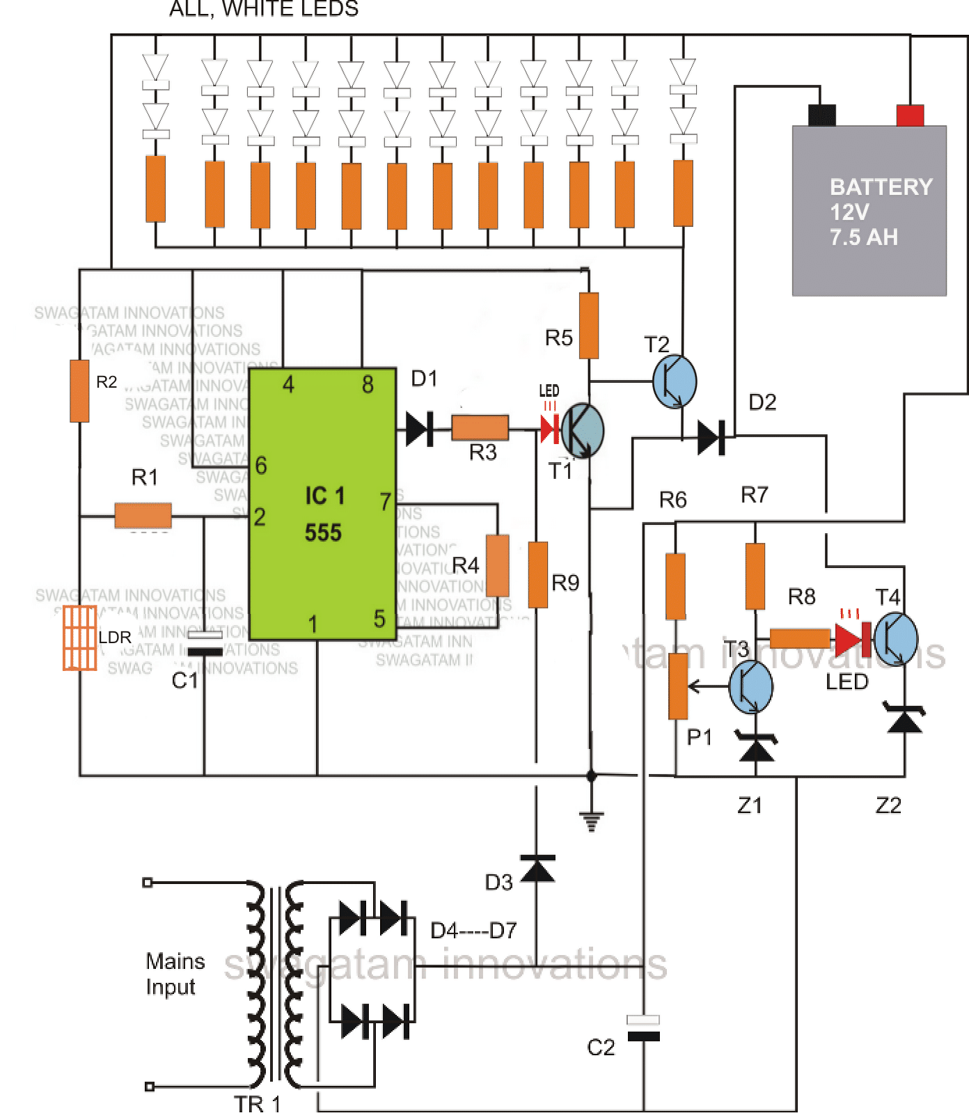
IC1 which is our very own IC555 has been set as a comparator. During day time, the light over LDR keeps the LDR resistance low such that the potential at pin #2 of the IC is kept well over 1/3Vcc. This situation ensures that the output of the IC at pin #3 stays at logic high.
The logic high at pin#3 of the IC keeps T1 switched ON, which consequently keeps T2 switched OFF.
With T2 switched OFF, the LED array remains inhibited from the ground connection and therefore the whole white LED array also stays shut off.
Another factor that keeps T1 switched ON and T2 switched OFF, is the voltage from the transformer power supply stage.
This function is implemented via the resistor R9. This also means that as long as mains AC is available, T2 is restricted from conducting and therefore the LEDs cannot light up.
Now suppose the mains power to the transformer fails, and assume that this happens during night or complete darkness, pin#3 of IC555 reverts to zero and also there's no voltage from the power supply, means T1 has absolutely no base bias and therefore has to switch OFF.
This instantly prompts T2 to switch ON and consequently the entire LED array also switches ON, providing the required emergency illumination to the surrounding.
MAKE SURE THAT THE LIGHT FROM THE LED DOES NOT FALL OVER THE LDR, WHICH MIGHT TRIGGER A RAPID UNDESIRABLE SWITCHING OF THE LEDS.
The battery charging section consists of T3, T4 and the associated parts. P1 is set such that it switches ON T3 when the battery voltage reaches just above 14 volts.
The moment this happens, T4 switches OFF, cutting of the negative supply to the battery and restricting any further charging of the battery.
Diode D2 ensures that the battery receives the negative supply during the charging process only through T4 and also provides a normal negative path to to T2 and the LED array when they conduct.
The left side LED indicates, mains power ON or presence of day light.
The LED at the right side indicates, battery is charging.
Parts List
- R1 = 2M2
- R2 = 1M
- R3, R4, R5, R9, R6, R7, R8 = 4K7
- ALL LED RESISTORS = 330 OHMS
- D1, D2, D3 = 1N4007
- D4----D7 = 1N5402
- C1 = 1000uF/25V
- C2 = 1uF/25V
- T1, T3 = BC547
- T4, T2 = BD139
- Z1, Z2 = 3V/400mW
- P1 = 10K PRESET
- IC1 = IC 555
- TRANSFORMER = 12V, CURRENT = 1/10 OF BATTERY AH
- LEDS = WHITE 5mm, OR AS PER CHOICE.
- BATTERY = 12V, AH = AS PER LED POWER AND BACK-UP REQUIREMENTS.
Using a Single PNP BJT
The above circuit can be much simplified by eliminating the IC555, and by using just a single PNP transistor instead of two NPN in the battery auto-battery cut of section.
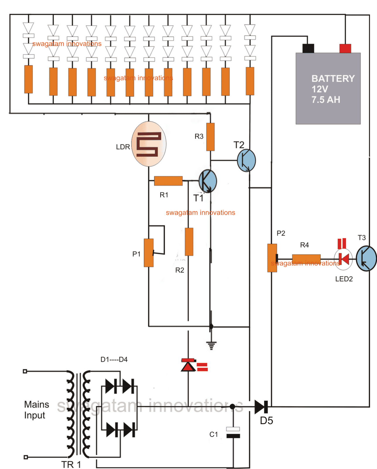
P1 is used for adjusting the ambient light threshold at which the LEDs stop illuminating.
P2 is set such that at 14.6V (across the battery terminals) the base LED becomes very dim, hardly visible, and at 12.5V it's brightly lit.
Adding a Solar Panel
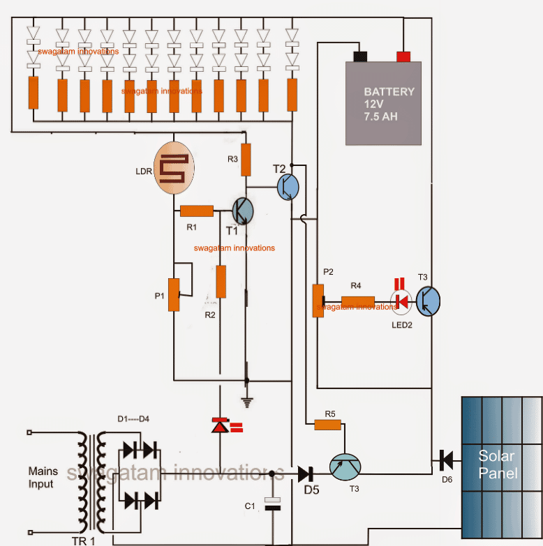
The above circuit can be also coupled with a solar panel for getting an automatic charging facility from both the sources that is from the panel during day time and from mains after the sun sets.
Parts List
R1,R2,R3, R4, R5 = 1K
P1 = 470K
P2 = 1K
C1 = 1000uF/25V
D1---D5 = 1N4007
T1 = BC547
T2 = 8050
T3 = TIP127
ALL LED RESISTORS = 330 OHMS
LEDS = WHITE, 5MM
LDR = ANY STANDARD TYPE
TRANSFORMER = 0-12/1AMP


Questions & Answers
for lower voltages how LDR's can be configured
ie which transistor should i use???
waiting for ur reply…………
Hello Tanmoy,
Using single resistor will make the LED brightness weaker and nonuniform.
the resistors distribute current equal among the LEDs creating uniform brightness and optimal response.
please check out this article
https://www.homemade-circuits.com/2011/12/how-to-wire-led-lights-easy-clues.html
hello abhishek sir
i gopal malviya from m.p. and i have just started by cfl repair and making
business but i dont have any good reasonable electronics parts supplier so please suggest me parts supplier vendor contact detail with your reference
Thanks for kind support
Gopal Malviya
hello sir
i gopal malviya from m.p. and i have just started my cfl repairing and making business but i don't have any good electronic parts supplier
so sir please suggest me any parts supplier with your reference
i'll thankfull for your
Thanks for Your Kind Support
Gopal Malviya
Good day sir!
I have some questions.
1.Can I replace the 12-0-12v 1A transformer with 15-0-15v 1A transformer then just use voltage regulator like LM7812 to regulate to 12v? Doesn't it affect the current?
7812 will not produce or allow more than 1amp at its output, irrespective of input current or voltage
sir can I use same circuit for using 12v 7w led and battery of 12v 2.5Ah and how much time transformer needs to charge battery of 2.5 ah fully
12V/2.5 ah will not support the led for very long, may be only for 30 minutes.
lead acid battery needs 10 hours to get charged correctly.
sir can I use same circuit for using 12v 7w led and battery of 12v 2.5Ah and how much time transformer needs to charge battery of 2.5 ah fully
Sir, I want to build the second circuit (without 555), but want to additionally incorporate a small solar panel for charging battery (first priority solar charging, second priority mains). Will be obliged if you please suggest a modification in circuit. safdar
aquaris, it can be done by a simple modification, i'll try to update it as soon as i get some free time.
I'm very delighted and thankful for your prompt response. I will look forward that u have time to advise a good circuit. To elaborate requirement further, the battery should normally be charged by solar panel, and if not sufficient, like cloudy days, it should auto switch to charging from mains till battery is fully charged (of course with overcharge protection). Thanks once again.
Thanks, I have updated the diagram please check it out.
Many thanks for the goodness. You are genius. I will build this circuit for my home and give u feedback soon.
You are welcome
hi
my battery is 12v and 7amp,so is there any problem. And i have Osram Dulux S/E 7W 4 Pin CFL – 827 so is it possible to connect that in this circuit.
hi how does the lamp work, please provide it's voltage and current specs for correct analysis.
also i have a 10w solar panel is it sufficient to use with this circuit
please provide its V and I ratings
when i measure the voltage and current of solar panel with multimeter i got 19.2 approx 20v and
current within .5A.
I dnt know the rating of that bulb
the solar panel can be used with the above circuit but after stepping down through a LM317 voltage regulator.
the OSRAM bulb tat you have mentioned is a fluorescent tube so it cannot be used directly with the above circuit.
Can you give me the circuit to connect LM317.
can i connect 12v 7ah battery?
can i use the given led bulb( 1w or 3w) in the link below in this circuit?
https://docs.google.com/file/d/0Bwgu3V_6cEZsdlZSRDM4QVJEcms/edit?pli=1
if it's a 1watt led you can connect it directly with the 12V battery through a 40 ohm 1 watt series resistor
how many 1w led bulb can be connected to 12v, 7ah battery (pls give the resistor value also) which give max brightness and backup hrs.
i am answering this for the second time, pls don't repeat your questions.
connect 3 leds in series with 6 ohm 1 watt resistor
make two such strings and connect their common ends with the battery
backup will be upto 3 to 4 hours
I dont want to use ldr can i used a switch instead of that.
yes surely, remove the T1/T2 stage entirely.
Friend i am little bit confused thats why im asking to many questions dont feel irritated.please tell me that if i want to connect the 1w led direclty to 12 7ah battery then how many can be connected to the battery so that i will get a back up of 6-8hrs
friend, make strings of 3 leds in series with a 6 ohm 1 watt resistor.
make 2 such strings and connect them in parallel (join their positive/negative ends together)
and connect the network to the battery.
2 strings in parallel having 3 leds in each string gives 3×2 = 6 leds
this would approximately run for 7 to 8 hours.
sir pls reply,
in the above comment you said to remove t1 t2 stage,then should i have to remove r1,r2,r3,p1 with that.
if yes then where i have to connect the led +ve and -ve.
I want to charge my 12v 7ah battery with this circuit pls tell me how.
….please repeat your exact requirement pointwise.
can i use the circuit in the link below with the above mentioned solar panel, battery and bulb
https://drive.google.com/file/d/0Bwgu3V_6cEZsaUp1ZUEtdmpMR2s/edit?usp=sharing
yes…
Can i use the above mentioned 1w (8Nos) led in this circuit.Will it give max light.
yes can be used.
Is it possible to show a charging led in this circuit.If yes pls tell me how to?
it's already there at the base of the transistor.
https://drive.google.com/file/d/0Bwgu3V_6cEZsZGZ6Y3R2WVRmSFk/edit?usp=sharing
i am using this circuit to charge 12v 7ah battery with the above mentioned solar panel.but its not charging is there any prblm in this circuit.if you have any better circuit to charge with solar panel pls give me.
check the output voltage without connecting the battery, it should be set to 14V, and the solar panel must be able to produce 1amp current minimum.
my panel is only producing a max of 430 mA is there any circuit to charge the 12v 7ah sla battery with this panel.
430mA will not charge 7AH batt…change the panel with a 1 or a 2amp variant
please also tell me that can i use circuit in the link below with 12v, 7ah battery to connect the led bulb shown in the above link with rating(Power: 1W, Voltage: DC 3.0V~3.2V,Current: 300~350mA).If yes then how long it will give light with that battery else please suggest an efficient circuit.
This is the link
https://docs.google.com/file/d/0Bwgu3V_6cEZsUjZhM2k3dXlhUGs/edit
yes can be used but the 317 will become very hot, use heatsink for it..
it may last for about 2 hours.
Sir I finally decided to make your circuit, i need your help during my assembling if any error arises. sir please answer each question.
Please reply as early as possible.
some doubts are
1) In the 2nd circuit does it have overcharge protection?If yes can you just elaborate please?
2) Sir please specify the rating of solar panel (max current and max voltage) in 3rd circuit?And how to show a charging indication for solar panel?
3) Sir i know you said that my solar panel(17.5-19v and 500mA) not capable of charging this battery eventhough if i am connecting that solar panel, can i connect it as shown in your circuit?
1) it will stop overcharging if the preset is correctly adjusted, but it's a crude circuit.
2) solar panel should be 15V/2amp for 7ah batery, the base led will indicate charging state of he batt.
3) yes can be done
sir i made the circuit but i have problem with the preset.pls help me to how to adjust it.
when i started adjusting a spark is coming from the 1k preset. so i stopped adjusting is that due to any wiring mistake .
please reply fast sir.
sir now its ok.
sir how long it take to charge the battery current charge is 12.68v?
sir how can i check my circuit that everything is working well?when i checked the output given to battery terminal without connecting battery it shows 13.00v and 400mA and the t3 base led lights up is it correct?
sir now ok your 2nd circuit is working but 3rd circuit i have problem.i want to use switch instead of ldr so i didnt use ldr,r1,p1.
and i didnt connected the white leds and the remaining circuit is completed without giving solar panel input.And when i give transformer input it gives only 400mA output without connecting battery terminals.