The MP1584 is a high-frequency asynchronous step-down DC-DC buck converter IC manufactured by MPS (Monolithic Power Systems). This IC is widely used for applications which demand high efficiency and a compact form factor, for example operating portable devices, IoT modules, and other low-power electronics.
Here's the complete datasheet for the MP1584:
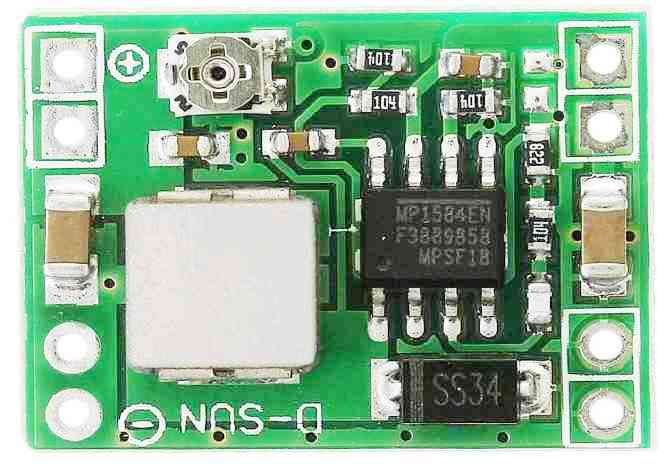
Electrical Characteristics
- Input voltage range: 4.5V to 28V
- Output voltage range: 0.8V to 20V
- Maximum output current: 3A
- Switching frequency: 500kHz (typical)
- Efficiency: up to 95%
- Quiescent current: 80μA (typical)
Pin Configuration
The MP1584 has a total of 8 pins:
- Pin 7: VIN - Input voltage pin
- Pin 1: SW - Switching node pin
- Pin 5: GND - Ground pin
- Pin 4: FB - Feedback pin
- Pin 3: COMP - Compensation pin
- Pin 2: EN - Enable pin
- Pin 8: BST - Soft-start/tracking pin
- Pin 6: FREQ - Frequency adjust pin
Features
The MP1584 buck converter module offers several features that make it a popular choice for step-down DC-DC conversion applications, including:
- Asynchronous rectification for high efficiency
- Adjustable output voltage
- Stable with ceramic capacitors
- Over-current protection
- Over-temperature protection
- Under-voltage lockout
- Soft-start
- Short-circuit protection
Package and Ordering Information
The MP1584 is available in several different package options, including SOIC8 and QFN10. Here's the ordering information for the SOIC8 package:
- MP1584EN-LF-Z: SOIC8 package, lead-free, RoHS compliant
- MP1584EN-LF-Z TR: SOIC8 package, lead-free, RoHS compliant, tape and reel packaging
And here's the ordering information for the QFN10 package:
- MP1584EN-LF-Z: QFN10 package, lead-free, RoHS compliant
- MP1584EN-LF-Z TR: QFN10 package, lead-free, RoHS compliant, tape and reel packaging
Environmental and Regulatory Compliance
- Operating temperature range: -40°C to +85°C
- Lead-free and RoHS compliant
- Halogen-free
Application Circuit Diagram
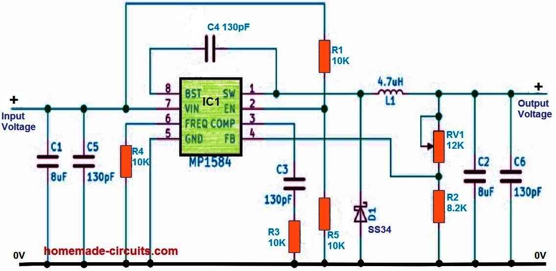
The MP1584 application circuit is a standard step-down DC-DC converter circuit that is meant to convert a larger input voltage to a smaller output voltage. Here's a full description of the circuit's different components and their capabilities:
VIN: The input voltage pin, to which you attach your input voltage source. The MP1584 accepts input voltages ranging from 4.5V to 28V and steps them down to the necessary output value.
SW: The switching node pin interfaces to an inductor, which stores and releases energy throughout the switching operation. The inductor is a component of the MP1584's internal control loop, and it facilitates in the regulation of the output voltage.
GND: The ground pin, which connects the ground of your input and output circuits.
The feedback pin (FB) is used to adjust the output voltage. To configure the desired output voltage, connect a voltage divider network between the output voltage and this pin.
COMP: The compensation pin is used to modify the stability of the feedback loop. To stabilize the feedback loop, put a capacitor between this pin and ground.
EN: The MP1584 may be powered on and off via this enable pin. To regulate the output voltage, you can link this pin to a switch or a logic signal.
The output voltage ramp-up time is adjusted using the SS/TR pin, which is also known as the soft-start/tracking pin. To adjust the ramp-up period, attach a capacitor between this pin and ground.
VOUT: You attach your output load to this pin, which is the output voltage pin. The MP1584 can provide an output current of up to 3A and a voltage range of 0.8V to 20V.
Conclusion
In summary, the MP1584 application circuit uses an inductor, a feedback network, and a control loop to regulate the output voltage.
The various pins on the IC are used to control the switching frequency, enable/disable the IC, and adjust the feedback loop stability and output voltage ramp-up time.
The application circuit is a basic building block for a wide range of DC-DC converter circuits, and it can be easily customized for different input and output voltage requirements.



Questions & Answers
Sir, I saw in this model that 104 resistors were fitted, but I calculated that the code for 10k is 103!
Neeraj, 104 means 10,0000 Ohms = 100K, 103 = 10,000 ohms = 10K
Then which resistor should I use in this module? 104 or 103??
I think both should work, since these are used for high impedance inputs of the IC.
However since 100K is shown in the real module you can use 100K.
Sir if i use 150pf capacitor instead of 130pf
Will this work ??
You can try 130pF instead of 150pF. It should work.
I don’t have 130pf capacitor that’s why I am using 150pf capacitor
yes, I meant to say 150 pF can be used instead of 130 pF.
Hello sir can this module take 15a as input current?
Neeraj, input amp is not important, it can be any value, 15 amp or 100 amp….but the input voltage must never exceed 20V.
But I am giving it almost 24v !!!!!
The MP1584 will burn if 20V is exceeded. Please see the specifications provided in the above article.
Input voltage range: 4.5V to 28V
Output voltage range: 0.8V to 20V
Input can be above 24v but not the output! More then 20v !
OK, Sorry for the confusion, yes the input is upto 28V, it was a mistake from me.
In that case 24V 15 amp is OK to be used as the input supply. No issues.
But still please try not to exceed 24V.
Sir I have another question from temperature sensing circuit as a puch botton feature I wanna use touch module but its requires 5v and I am not able to reduce 12v to just 5v so can I use some transistor that generates frequency and after touching it it’s gives command to the circuit to on ? Just like touch module
Btw thanks for your all the support ??
Neeraj, which touch module do you want to use?
Please continue discission under the temperature sensing circuit.
Hello sir how are you I hope you are fine I have a question can I use this step-down module with 48v input I think I can’t but can you suggest me something same as it and same size because it’s so small and cute I am going to use this for my 5v dc motor and the input is 48v smps help me sir suggest me something
Hi Alfa, the above circuit can handle a maximum of 28 V input, so it won’t work with a 48V input.
For a 48V input you can try the following concept:
https://www.homemade-circuits.com/0-to-50-v-adjustable-switching-power-supply-circuit-using-ic-lm2576/
sir I wanna know all the parts information including circuit diagram for mp4560 5v module !
Neeraj, all the details are given in the following datasheet, please read it carefully to understand all the details that are provided here:
https://www.monolithicpower.com/en/documentview/productdocument/index/version/2/document_type/Datasheet/lang/en/sku/MP4560/document_id/305/
If you need any specific help regarding the topic, you can ask me, I will try to clarify.
sir this module can make 3.3v, 5v, 9v and 12v can you make any modification for 7v ? and 8 v ?
Hi Neeraj, The MP4560 circuit allows you to get any voltage between 3.8V to 55V, as desired by you, simply by adjusting the values of the resistors R1 and R2.
You can use the following software to calculate the R1, R2 values:
https://www.homemade-circuits.com/voltage-divider-calculator-software-potential-divider-calculator/
For Input Voltage enter 7 or 8.
for Output Voltage enter 0.802
Do not change anything for Resistor Sequence: and Resistor Scale (Ohms):
press calculate.
sir couldn’t we add a preset ?
this will be great for everything!
Yes, that’s possible.
Connect the wiper arm of the preset with the FB pin of the IC, and connect the other two outer terminals of the preset with the IC output +/- terminals.
what’s the value of the preset and how can we directly connect it with nay resistance change in the module ?
If you are using a preset then the value does not matter, you can use a 10k preset or a 22k, or 47k or a 100k all will work.
Are the resistors in the schematic above that are labeled 10K supposed to be 100K. The pic shows 104 on the resistors. Thanks
R1 and R5 can be 100k, but the remaining resistor values will depend on the selected frequency and the other parameters which might differ from board to board. So the module in the first image may have resistor values depending on the selected capacitor, frequency, inductor values which may differ with the circuit diagram.
If you want a perfectly accurate diagram then you may refer to the datasheet of the IC:
I was just looking at the numbers on the resistors in the pic and thinking to myself I have been converting wrong. 🙂
Also I wanted to say thanks for all the info on the blog. It really does help me. I’m new at this stuff but having a good time trying to learn.
You are most welcome Steve, glad you found this site helpful!
Can it be able to give two outputs? I mean, I want to give 12V 2A as input, and I want two outputs like 3.3V 2A and 5V 2A. Is it possible to use fixed resistor values to get those outputs?
That’s possible, but you cannot use both the outputs simultaneously, you can use them one at a time…
In the Features section it states “Synchronous rectification for high efficiency”.
The operation of the MP1584 is non-synchronous.
Thanks!…Done!!