If you are wondering how to correctly use white LEDs in circuits so that they can be illuminated safely without damaging, then this post might help you to evaluate the same.
Introduction
White LEDs are the future lighting solutions for our cities and homes. They will be easily replacing the traditional CFL and other flurescent types of light producing devices. LEDs are extremely efficient when it comes to power consumption issues and are also highly durable and reliable with its specified features.
The invention of LED technology was a complete revelation, and it opened the doors to the researchers for exploring a whole new concept of lighting involving tiny devices which could produce immense illumination using very little electric power.
Today the concept may look old, yet still, LEDs especially white LED technology is improving at a very rapid pace. LED industry is surely growing and introducing advanced and more efficient versions of LEDs to us. Also these devices are getting very popular even with the common population and folks are seen using them and customizing them as per there own preferences.
Though white LEDs may look simple devices and illuminating them may not require more than a couple of pen light cells, white LEDs if not maintained or operated within a specific power range, might just fail in every respect.
Here we are going to discuss some of the basic tips regarding operating or illuminating these wonderful devices safely and optimally.
Before studying the above through a simple application circuit, it would be important to understand some of the following important specifications related to white LEDs.
Important Specifications associated with White LEDs
In general most of the white LED types are specified with a maximum forward voltage drop of not more than 3.5 volts AC/DC.
Forward voltage drop means the maximum safe operating voltage of a particular LED at which the LED illuminates with maximum intensity without the danger of getting damaged.
The minimum current required by most white LED types at the above voltage is 10 mA, 20 mA being the optimal range, however these devices are able to operate even with 40 mA of current, producing dazzling brightness, almost at eye blinding levels.
Normal 5mm and 3mm types of white LEDs have two lead terminals, assigned as the cathode and the anode, or in layman’s words, a positive and a negative.
The cathode or the negative lead is relatively smaller in length than the anode or the positive lead and this also makes the terminals easily distinguishable.
For operating the device, the longer lead is connected to the positive while the smaller lead is connected with the negative of the power supply.
If the connected power to the LED is within the specified 3.5 volt range, then a series resistor may not be required to be connected with the LED.
However, if the supply voltage is more than the above limit, inclusion of a resistor becomes imperative.
Failing to do so may the burn the LED and damage it instantly.
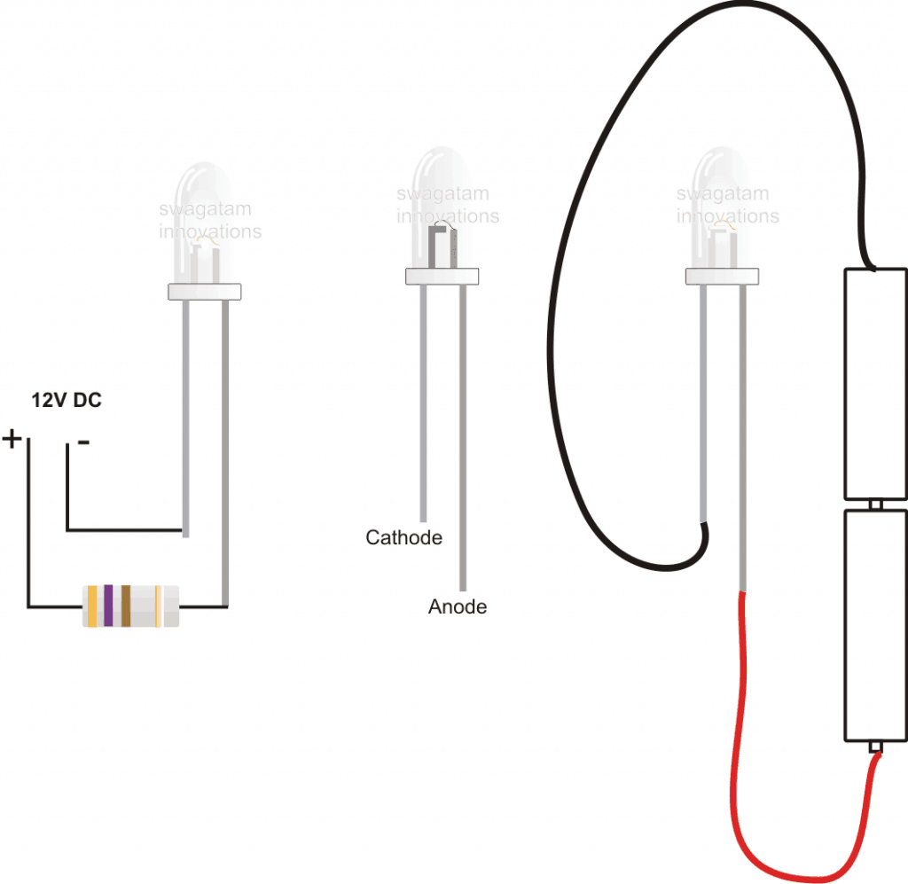
The value of the of the resistor will depend on the magnitude of the applied voltage, and may be calculated using the following formula:
R = (Us – Fwd.)/I(current),
where R is the resistance value which needs to be calculated, Us is the supply voltage, Fwd is the forward voltage drop of the LED and I is the current magnitude which is required to be supplied to the LED.Suppose the supply voltage is 12, the forward voltage drop and the current as explained above are taken as 3.5 and 20 respectively, R may be calculated as:
R = (12 – 3.5)/0.02 = 425 Ohms.
In general the forward voltage drop of a particular LED becomes the important factor while issuing the operating input to the device, rest of the parameters ae not absolutely critical.
The forward voltage drop of an LED may be easily found out by connecting the particular device to a digital multimeter prods selected at the diode range.
The displayed figure directly provides the forward voltage range of the particular LED.


Questions & Answers
Forward voltage drop means the maximum safe operating voltage of a particular LED at which the LED illuminates with maximum intensity without the danger of getting damaged.
Wrong: Forward voltage in the minimum voltage to make a led glow.
Technically that may be true, but practically a 3.3 V LED illuminates even at less than 3V, and exceeding this 3.3 V limit makes the LED warmer and vulnerable, and the LED might start losing its life in the long run.
So in a real life situation the forward voltage of an LED is the value which must be never exceeded, unless a limiting resistor is used..
Hi,
Just personnal things…
I worked for a company in hyd, as an electronics engineer for maintenance of smart card based time attendance systems, token issue systems, access control systems. That company was merged with other one and I came out.
I worked as an electronics testing engineer for one company in hyd, They used to make regulated power supplies, function generators, oscilloscopes etc. This one was also take over by another one.
I worked for a company as production incharge, which will make lights using leds ( CREE, NICHIE)
as downlights, decoration lights, flood lights, street light, charge controllers which will be used in solar controllers. Due to loss, that one was closed.
Now, I am searching a job. Having experience in electronics field more than 10 years, I didnot settle yet. Can you please suggest me something so that i will be settled in the life.
Thank you
I'll try to find an opportunity for you, you can keep in touch with me through my ID
hitman2008@live.in
Hi.
Very Nice yours site.
How can I buy a White LED?
Is LED gives cool white light? or something else? how can I know?
The same LED can be used for both AC and DC Supplies? or not?
How can I know?
Hi thanks!
You can buy leds from any electronic spare part retailer.
LEDs give cool white light
LEDs work on both AC/DC, only the current needs to be restricted.
Swagatam
I don't know how to praise you and thank you.
You for helping many and solving lots problems. It will effect on the society.Slow each one will become self reliant
Congratulations
Hello Babu,
Thank you! I appreciate and respect your words.
Hi,i need to consult you on something,kindly give me your email address.ptah.ayuo@students.uonbi.ac.ke
Hi, please feel free to discuss here through your comments, it is best place to share our electronic related problems and solutions…