A single state-of-the-art chip, a transistor and a few other inexpensive passive components are the only materials required for making this outstanding, self regulating, over charge controlled, automatic NiMH battery charger circuit. Let’s study the whole operation explained in the article.
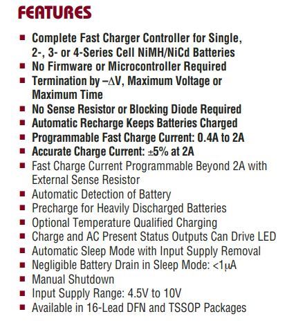
Main Features:
How the Charger Circuit Works
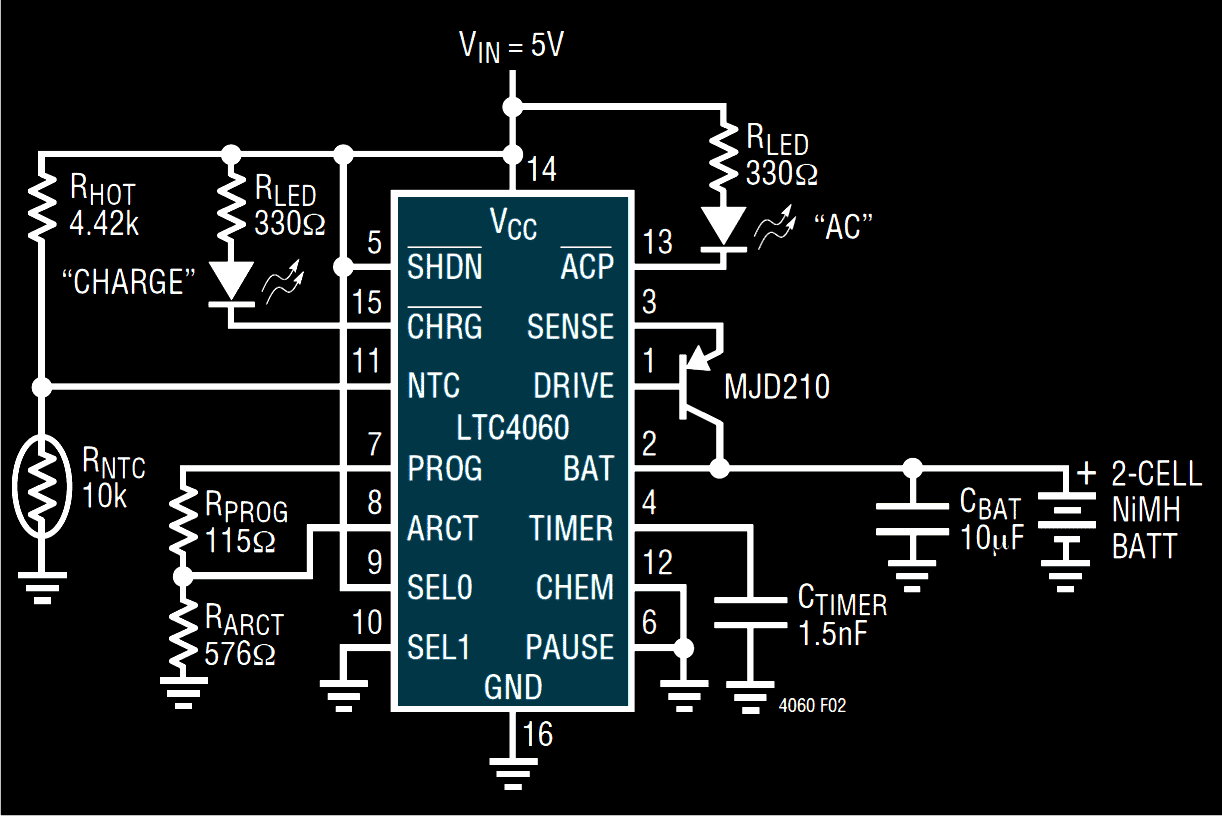
Referring to the diagram we see a single IC being used which alone performs the function of a versatile high grade battery charger circuit and offers utmost protection to the connected battery while it’s being charged by the circuit.
This helps to keep the battery in a healthy environment and yet charge it with a relatively rapid rate. This IC ensures a high battery life even after many hundreds of charging cycles.
The internal functioning of the NiMH battery charger circuit can be understood with the following points:
When the circuit is not powered, the IC enters into a sleep mode and the loaded battery is disconnected from the relevant IC pin out by the action of the internal circuitry.
The sleep mode is also triggered and the shut down mode is initiated when the supply voltage exceeds the specified threshold of the IC.
Technically, when the Vcc goes above the ULVO (under voltage lock out) fixed limit, the IC triggers the sleep mode and disconnects the battery from the charging current.
The ULVO limits are defined by the potential difference level detected across the connected cells. This means the number of cells connected determines the shut down threshold of the IC.
The number of cells to be connected must be initially programmed with the IC through suitable component settings; the issue is discussed later on the article.
The rate of charging or the charging current can be set externally through a program resistor connected to the PROG pin out of the IC.
With the present configuration an inbuilt amplifier causes a virtual reference of 1.5 V to appear across the PROG pin.
This means that now the programming current flows through an in built N channel FET toward the current divider.
The current divider is handled by the charger state control logic which produces a potential difference across resistor, creating a fast charging condition for the connected battery.
The current divider is also responsible for providing a constant current level to the battery through the pin Iosc.
The above pin out in conjunction with a TIMER capacitor determines an oscillator frequency used for delivering the charging input to the battery.
The above charging current is activated through the collector of the externally connected PNP transistor, while its emitter is rigged with the IC’s SENSE pin out for providing the charging rate information to the IC.
Understanding the pinout functions of the LTC4060
Understanding the pin outs of the IC will make the building procedure of this NiMH battery charger circuit easier, let's go through the data with the following instructions:
DRIVE (pin #1): The pin is connected to the base of the external PNP transistor and is responsible for providing the base bias to the transistor. This is done by applying a constant sink current to the base of the transistor. The pin out has current protected output.
BAT (pin #2): This pin is used to monitor the charging current of the connected battery while it is being charged by the circuit.
SENSE (pin #3): As the name suggests it senses the charging current applied to the battery and controls the conduction of the PNP transistor.
TIMER (pin #4): It defines the oscillator frequency of the IC and helps to regulate the charge cycle limits along with the resistor that’s calculated at the PROG and GND pin outs of the IC.
SHDN (pin #5): When this pin out is triggered low, the IC shuts down the charging input to the battery, minimizing the supply current to the IC.
PAUSE (pin #7): This pin out may be used for stopping the charging process for some period of time. The process may be restored by providing a low level back to the pin out.
PROG (pin #7): A virtual reference of 1.5V across this pin is created through a resistor connected across this pin and ground. The charging current is 930 times the level of the current that flows through this resistor. Thus this pinout may be used for programming the charging current by altering the resistor value appropriately for determining different charging rates.
ARCT (pin #8): It’s the auto-recharge pinout of the IC and is used for programming the threshold charge current level. When the battery voltage falls below a preprogrammed voltage level, the charging is reinitiated instantly.
SEL0, SEL1 (pin #9 and #10): These pin outs are used for making the IC compatible with different number of cells to be charged. For two cells, SEL1 is connected to ground and SEL0 to the supply voltage of the IC.
How to Charge 3 Series Number of Cells
For charging three cells in series SEL1 is rigged to the supply terminal while SEL0 is wired up to the ground. For conditioning four cells in series, both the pins are connected to the supply rail, that is to the positive of the IC.
NTC (pin #11): An external NTC resistor may be integrated to this pin out for making the circuit work with respect to the ambient temperature levels. If the conditions become too hot the pin out detects it through the NTC and shuts down the proceedings.
CHEM (pin #12): This pin out detects the battery chemistry by sensing the negative Delta V level parameters of NiMH cells and selects the appropriate charging levels as per the sensed load.
ACP (pin #13): As discussed earlier, this pin detects the Vcc level, if it reaches below the specified limits, in such conditions the pinout becomes high impedance, shutting down the IC in sleep mode, and shutting off the LED. However, if the Vcc is compatible with respect to the battery full charge specifications, then this pinout turns low, illuminating the LED and initiating the battery charging process.
CHRG (pin #15): An LED connected to this pin out provides the charging indications and indicates that the cells are being charged.
Vcc (pin #14): It’s simply the supply input terminal of the IC.
GND (pin #16): As above it’s the negative supply terminal of the IC.


Questions & Answers
I am not an electronic engineer but I can replicate … can this circuit work to charge 5 AA batteries ??? if yes do I get the list parts from the diagram ??? and is there anything I should change or upgrade !!!
I don’t think 5 AA cells can be accommodated in this circuit, but 4 cells can be charged comfortably in series, as per the datasheet of the IC.
thanks for the feed-back. So I asume 4 cells 4 x 1.5 volts = 6.0 volt is the max allowed, is this correct ???
yes that’s perfectly correct!
Thanks…. I have old film cameras, with old battery packs and I am trying to re-build them with ni-mh (serial connected) , therefore I have the need for a “custom charger”
This circuit would only work for 6v ? regardless of the number of batteries connected as log the do not excede 6v ??? right !?! I am civil engineer and I have some idea of electrical circuits is there a opportunity to have a 10V nicd or nimh serial circuit ???
Hi Peter, With this circuit it may not be possible to charge cells with 10V, however you can safely use an LM317 circuit for this. Just make sure that the voltage is adjusted just below the recommended full charge level of the cells. Meaning suppose if the recommended full charge level is 10V then make it 9.8V, this will ensure that under no condition the cells are subjected to continuous charging even after they have reached the full charge level, therefore no auto cut-off would be required. This would also ensure a long life for the cells.
You can implement the following circuit:
https://www.homemade-circuits.com/how-to-make-current-controlled-12-volt/
What I great site you have created!
I’m wanting to use this circuit to charge NiMH batteries from a small 5.5v solar panel, so I’m looking at using a Low-dropout regulator to supply the VIN of your circuit with 5vdc. When my solar panel’s voltage drops below the 5vdc in low light, I’m assuming the Low-dropout regulator will drop it’s output to Zero until the solar panel can generate >=5vdc again. Am I going the right direction here?
Thanks
Glad you liked my site! Actually you can use any discretely built charger having CC and CV for charging a given battery. As for this charger I don’t see anything specified in the design that would cause the output to shut down when the input goes below 5V? So I don’t think that would happen. But the voltage may finally be insufficient to charge the battery and thus force the system to shut down eventually.
Thank you for your site, there is a ton of information. My son wants to create a solar powered battery charger for two AA Ni-mh batteries, 2300 mah each as an 8th grade science experiment. He will use solar cells 5V with up to 900ma.
Will this circuit work for his application? Will he need to have someone programm the IC chip before he builds the charger?
Glad you liked my site! Yes this circuit will definitely work if built and optimized correctly, although this may appear slightly difficult for a 8th grade student
Sir MJD210 is not available. Please givesome alternative?
Waiting for your kind reply.
You can try TIP127
Sir, will it affect the circuit?
It will not affect the circuit
Sir, the LED will go-off when full charge?
And For Charging single cell which SET condition, I have to make?
Shalin, yes it will, however I think there’s no provision for a single cell charging, minimum is two…
Sir Can you give me some 2-3 equivalent please??
Shalin, there are no exact equivalent of TIP127 or the MJD210 according to me, however you ca try 8550 transistor or BD140 and see if these work.
Sir if the 2 batteries are in different mAh, then also it will xharge th batteries perfectly?
Yes still it will charge until both the cells are charged fully.
Sir which type of capacitor is this?
The above capacitor is electrolyte type?
The 10uF is electrolytic
What about other capacitor?
Sir some of the values of the resistor is not available in market??
What to do?
You can adjust the values by adding series parallel resistors….
Like 2.2k+2.2k+0.01k+0.01k=4.42k
Is that correct?
Yes that’s correct, you can use any combination that may be available with you.
But If used 4 capacitor in series, will it affect the circuit because number of capacitors are relatively high?. Otherwise can I use directly 4.7k ohm resistor?
capacitors or resistors!
Sorry Sir, Resistor…Typing mistake
It won’t matter, you can use any number of resistors, only the value needs to exact.
1.5nF is ceramic type?
yes ceramic will do!
Instead of using ceramic type for 1.5nF, Film capacitor are very accurate than ceramic?
Am I right?
Yes that’s right!
If we are using 5V regulated SMPS supply, then what’s the need of AC diode portion, I mean we can connect 13th and 14th pin directly without resistor and LED?
Is that fine?
in 13 is the undervolatge lockout indicator. If the supply Vcc is less than the battery full charge then the IC will shut down, and the ACP LED will be off.
If we are using 5V regulated supply, then can we leave the ACP pin empty?
yes, but the Vcc must be higher than the total full charging voltage of the batteries, otherwise the IC shut down and go to sleep mode
Ok, but I am charging 1.2×2 batteries, so 5V is enough?
Am I right?
Also giving a current about 2300 mAh. Is that current value is fine?
Then 5 V is OK, you can remove the pin13 components. Please check the datasheet to find the maximum current of the circuit.
Sir, I started the project, Now came into trouble, I don’t have much experience with electronics, plz guide me to choose the max. Current limit for IC4060?
Daniel, the circuit diagram shown in the above article will fast charge your 2400 mAh battery at 2 amp rate, so you can apply the shown design
Hy Swagatam,
Have You a schematic for recharging Ni-MH batteries with capacitors by means a Joule Thief circuit?
I designed one for a particular application but I am not sure it with all safety precautions as for IC as above.
I should power up a 12V microfan and 4 (four) white LEDs, by storing the energy for the battery from the supercaps, loaded with a surplus of energy coming from the nulling of back EMF by the bucking winding of the transformer.
Can You support me thereabouts?
Thanks and regards,
Riccardo Tarelli
Hi Ricardo, the energy from the back EMF has to be significantly strong to be able to charge the Ni-Mh cells.
If it is, then you can use any standard joule thief circuit, by upgrading its current rating through thicker coil winding and adequately rated transistor.
If you can provide the specifications of all the parameters, including the back EMF, I may try to solve it for you!!
Hy Swagatam,
Certainly when I completed the design I will announce this to You in order to check if something has gone wrong! : -)
I hope to be successful with your precious support! 🙂
Thanks and regards,
Riccardo
No problem Riccardo, I wish you all the best with the project!
I want to power this cicuit via a solar panel to maintain charge in 4xNimh 1.5v batteries in my cat flap. Will i need to use a controller between the panel and charger circuit?
Thanks
You can use a 7809 voltage regulator IC between the solar panel and the above battery charger module…