In this article I will try to explain the basic concept of a solar inverter and also how to make a simple yet powerful solar inverter circuit.
Solar power is abundantly available to us and is free to use, moreover it’s an unlimited, unending natural source of energy, easily accessible to all of us.
What's so Crucial about Solar Inverters?
The fact is, there's nothing crucial about solar inverters. You can use any normal inverter circuit, hook it up with a solar panel and get the required DC to AC output from the inverter.
Having said that, you may have to select and configure the specifications correctly, otherwise you may run the risk of damaging your inverter or causing an inefficient power conversion.
Why Solar Inverter
We have already discussed how to use solar panels for generating electricity from solar or sun power, in this article we are going to discuss a simple arrangement which will enable us to use solar energy for operating our household appliances.
A solar panel is able to convert sun rays into direct current at lower potential levels. For example a solar panel may be specified for delivering 36 volts at 8 amps under optimal conditions.
However we cannot use this magnitude of power for operating our domestic appliances, because these appliances can work only at mains potentials or at voltages in the ranges of 120 to 230 V.
Further more the current should be an AC and not DC as normally received from a solar panel.
We have come across a number of inverter circuits posted in this blog and we have studied how they work.
Inverters are used for converting and stepping up low voltage battery power to high voltage AC mains levels.
Therefore inverters can be effectively used for converting the DC from a solar panel into mains outputs that would suitably power our domestic equipment.
Basically in inverters, the conversion from a low potential to a stepped up high mains level becomes feasible because of the high current that’s normally available from the DC inputs such as a battery or a solar panel. The overall wattage remains the same.
Understanding Voltage Current Specifications
For example if we supply an input of 36 volts @ 8 amps to an inverter and get an output of 220 V @ 1.2 Amps would mean that we just modified an input power of 36 × 8 = 288 watts into 220 × 1.2 = 264 watts.
Therefore we can see that it’s no magic, just modifications of the respective parameters.
If the solar panel is able to generate enough current and voltage, its output may be used for directly operating an inverter and the connected household appliances and also simultaneously for charging a battery.
The charged battery may be used for powering the loads via the inverter, during night times when solar energy is not present.
However if the solar panel is smaller in size and unable to generate sufficient power, it may be used just for charging the battery, and becomes useful for operating the inverter only after sunset.
Circuit Operation
Referring to the circuit diagram, we are able to witness a simple set up using a solar panel, an inverter and a battery.
The three units are connected through a solar regulator circuit that distributes the power to the respective units after appropriate regulations of the received power from the solar panel.
Assuming the voltage to be 36 and the current to be 10 amps from the solar panel, the inverter is selected with an input operating voltage of 24 volts @ 6 amps, providing a total power of about 120 watts.
A fraction of the solar panels amp which amounts to about 3 amps is spared for charging a battery, intended to be used after sunset.
We also assume that the solar panel is mounted over a solar tracker so that it is able to deliver the specified requirements as long as the sun is visible over the skies.
The input power of 36 volts is applied to the input of a regulator which trims it down to 24 volts.
The load connected to the output of the inverter is selected such that it does not force the inverter more than 6 amps from the solar panel. From the remaining 4 amps, 2 amps is supplied to the battery for charging it.
The remaining 2 amps are not used for the sake of maintaining better efficiency of the whole system.
The circuits are all those which have been already discussed in my blogs, we can see how these are intelligently configured to each other for implementing the required operations.
For complete tutorial please refer to this article: Solar Inverter Tutorial
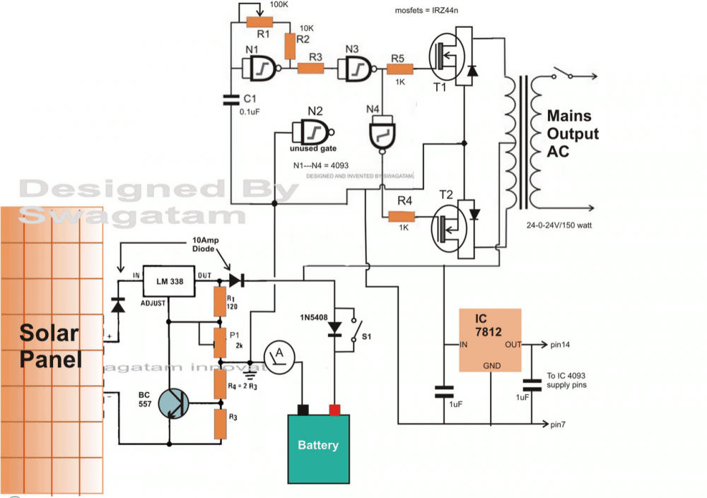
Parts List for the LM338 charger section
- All resistors are 1/4 watt 5% CFR unless specified.
- R1 = 120 ohms
- P1 = 10K pot (2K is mistkanly shown)
- R4 = replace iit with a link
- R3 = 0.6 x 10 / Battery AH
- Transistor = BC547 (not BC557, it's mistakenly shown)
- Regulator IC = LM338
- Parts List for the inverter section
- All parts are 1/4 watt unless specified
- R1 = 100k pot
- R2 = 10K
- R3 = 100K
- R4, R5 = 1K
- T1, T2 = mosfer IRF540
- N1---N4 = IC 4093
Remaining few of the parts does not need to be specified and can be copied as shown in the diagram.
For Charging Batteries up to 250 Ah
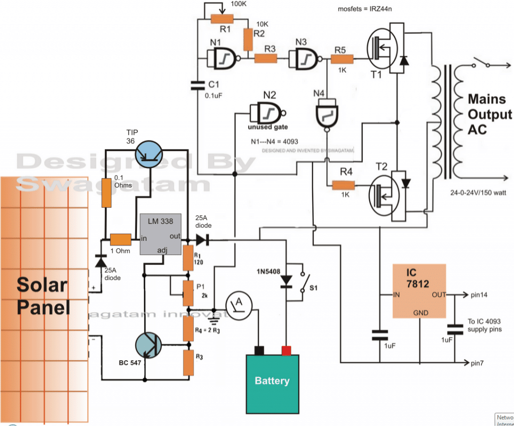
The charger section in the above circuit may be suitably upgraded for enabling the charging of high current batteries in the order of 100 AH to 250 Ah.
For 100Ah battery you can simply replace the LM338 with LM196 which is a 10 amp version of the LM338.
An outboard transistor TIP36 is appropriately integrated across the IC 338 for facilitating the required high current charging.
The emitter resistor of TIP36 must be calculated appropriately otherwise the transistor might just blow off, do it by trial and error method, start with 1 ohm initially, then gradually go on reducing it until the required amount of current becomes achievable at the output.
Adding a PWM Feature
For ensuring a fixed 220V or 120V output a PWM control could added to the above designs as shown in the following diagram. As can be seen the gate N1 which is basically configured as a 50 or 60Hz oscillator, is enhanced with diodes and a pot for enabling a variable duty cycle option.
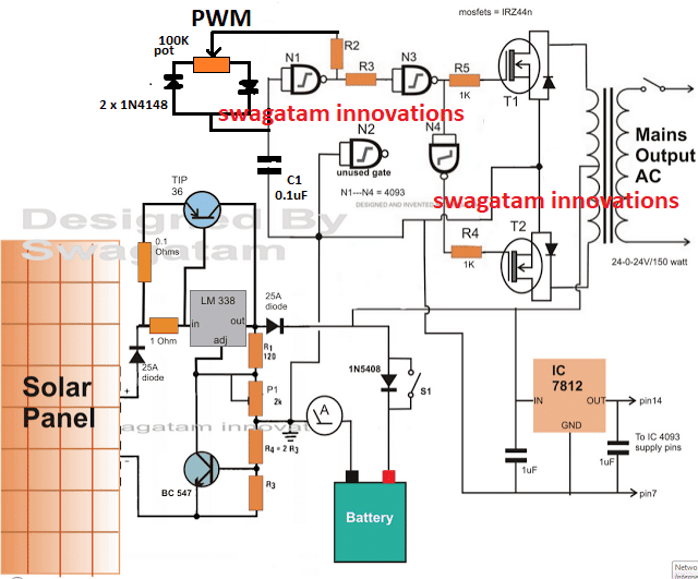
By adjusting this pot we can force the oscillator to create frequencies with different ON/OFF periods which will in turn enable the mosfets to turn ON and OFF with the the same rate.
By adjusting the mosfet ON/OFF timing we can proportionately vary the current induction in the transformer, which will eventually allow us to adjust the output RMS voltage of the inverter.
Once the output RMS is fixed, the inverter will be able to produce a constant output regardless f the solar voltage variations, until of course the voltage drops below the voltage specification of the transformer primary winding.
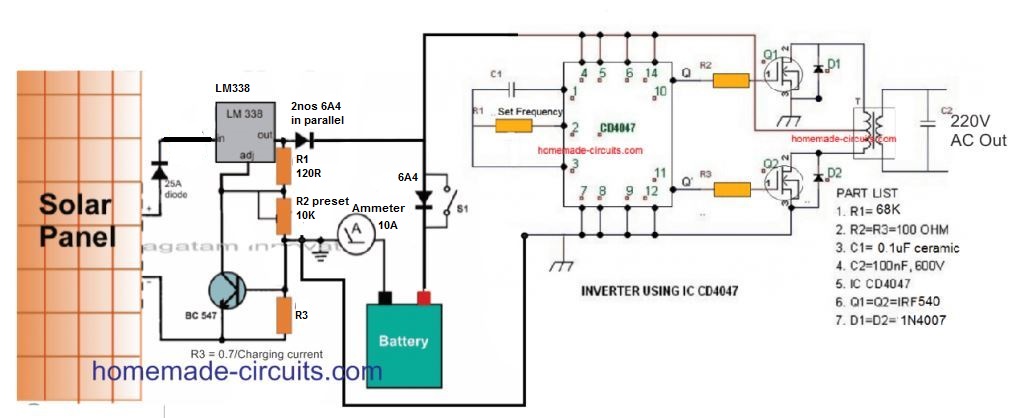
Solar Inverter Using IC 4047
As described earlier, you can attach any desired inverter with a solar regulator for implementing an easy solar inverter function.
The following diagram shows how a simple IC 4047 inverter can be used with the same solar regulator for getting 220 V AC or 120 V AC from the solar panel.
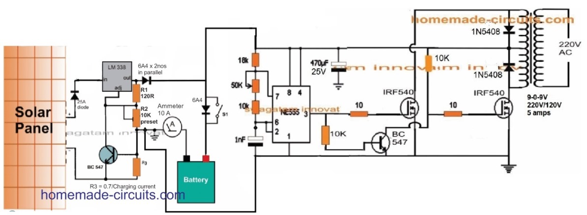
Solar Inverter using IC 555
Quite similarly if you are interested to build a small solar inverter using IC 555, you can very well do so, by integrating an IC 555 inverter with solar panel for getting the required 220V AC.
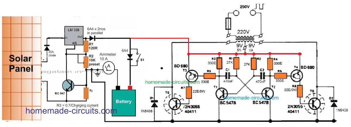
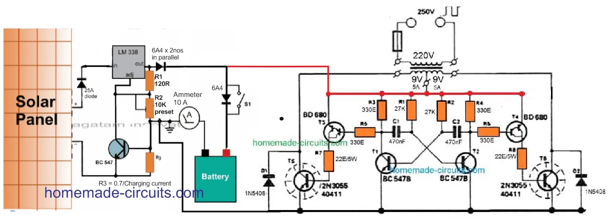
Solar Inverter using 2N3055 Transistor
The 2N3055 transistors are very popular among all electronic enthusiasts. And this amazing BJT allows you to build pretty powerful inverters with minimum number of parts.
If you are one of those enthusiasts who have a few of these devices in your junk box, and are interested to create a cool little solar inverter using them, then the the following simple design can help you to fulfill your dream.
Simple Solar Inverter without a Charger Controller
For users who are not too keen on including the LM338 charger controller, for simplicity sake, the following simplest PV inverter design looks good.
Even though the battey can eb seen without a regulator, the battery will still get charged optimally, provided the solar panel gets the required adequate amount of direct sunshine.

The simplicity of the design also indicates the fact that lead acid batteries are not so difficult to charge after all.
Remember, a fully discharged battery (below 11V) may require at least 8 hours to 10 hours of charging until the inverter can be switched ON for the required 12V to 220V AC conversion.
Simple Solar to AC Main Changeover
If you want your solar inverter system to have the facility of an automatic changeover from solar panel to mains grid AC, you can add the following relay modification to the LM338/LM196 regulator input:
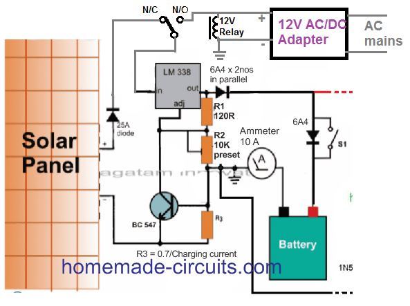
The 12V adapter should be rated to suit the battery voltage and the Ah specs. For example if the battery is rated at 12 V 50 Ah, then the 12V adapter can be rated at 15V to 20 V and 5 amp
Solar Inverter using Buck Converter
In the above discussion I have explained how to make simple solar inverter with battery charger using linear ICs like LM338, LM196, which are great when the solar panel voltage and current are same as the inverter's requirement.
In such cases the wattage of the inverter is small and restricted. For inverters loads with significantly higher wattage, the solar panel output power will also need to be large and on par with the requirements.
In this scenario, the solar panel current will need to be significantly high. But since solar panel are available with high current, low voltage making high wattage solar inverter in the order of 200 watt to 1 kva does not look easily feasible.
However, high voltage, low current solar panels are easily available. And since wattage is W = V x I, solar panels with higher voltages can easily contribute to a higher wattage solar panel.
That said, these high voltage solar panels cannot be used for low voltage, high wattage inverter applications, since the voltages may not be compatible.
For example, if we have a 60 V, 5 Amp solar panel, and a 12 V 300 watt inverter, although the wattage rating of the two counterparts may be similar, they cannot be hooked up due to voltage/current dissimilarities.
This is where a buck converter comes very handy and can be applied for converting the excess solar panel voltage to excess current, and lowering the excess voltage, as per the inverter requirements.
Making a 300 Watt Solar Inverter Circuit
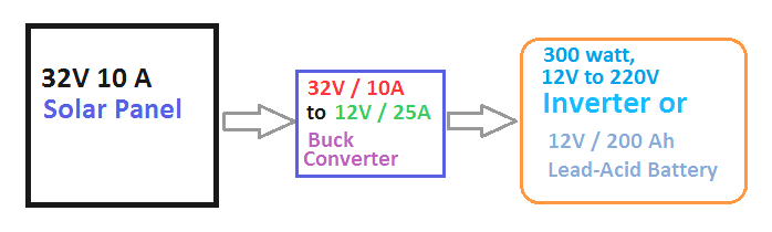
Let's say we have want to make a 300 watt 12 V inverter circuit from a solar panel rated with 32 V, 15 Amps.
For this we will need an output current of 300/12 = 25 Amps from the buck converter.
The following simple buck converter from ti.com looks extremely efficient in providing the required power for our 300 watt solar inverter.
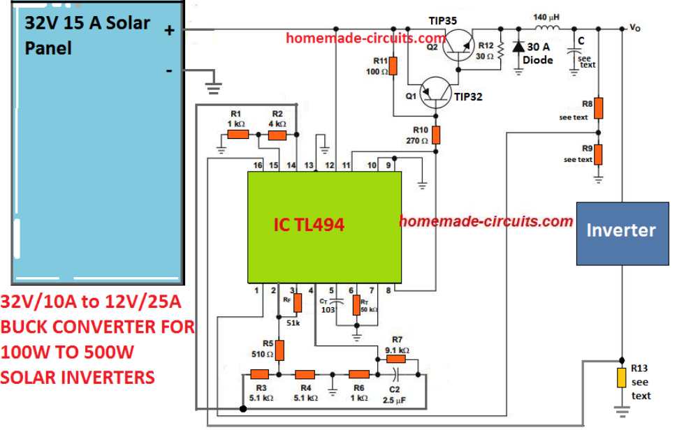
We fix the important parameters of the buck converter as given in the following calculations:
Design Requirements
• Solar Panel Voltage VI = 32 V
• Buck Converter Output VO = 12 V
• Buck Converter Output IO = 25 A
• Buck Converter Operating Frequency fOSC = 20-kHz switching frequency
• VR = 20-mV peak-to-peak (VRIPPLE)
• ΔIL = 1.5-A inductor current change
- d = duty cycle = VO/VI = 12 V/32 V = 0.375
- f = 20 kHz (design objective)
- ton = time on (S1 closed) = (1/f) × d = 7.8 μs
- toff = time off (S1 open) = (1/f) – ton = 42.2 μs
- L ≉ (VI – VO ) × ton/ΔIL
- ≉ [(32 V – 12 V) × 7.8 μs]/1.5 A
- ≉ 104 μH
This provides us the specifications of the buck converter inductor. The wire SWG can be optimized through some trial and error. A 16 SWG super enameled copper wire should be good enough to handle 25 Amps current.
Calculating the Output Filter Capacitor for the Buck Converter
After the output buck inductor is determined, the value of the output filter capacitor can be worked out to match the output ripple specifications. An electrolytic capacitor could be imagined like a series relationship of an inductance, a resistance, and a capacitance. To offer decent ripple filtering, the ripple frequency has to be much lower than the frequencies where the series inductance becomes critical.
Therefore, both the crucial elements are the capacitance and the effective series resistance (ESR). highest ESR is calculated in line with the relationship between the chosen peak-to-peak ripple voltage and the peak-to-peak ripple current.
ESR = ΔVo(ripple) / ΔIL = V/1.5 = 0.067 Ohms
The lowest C capacitance value recommended to take care of the VO ripple voltage at smaller than the 100-mV design requirement is expressed in the following calculations.
C = ΔIL / 8fΔVo = 1.5 / 8 x 20 x 103 x 0.1 V = 94 uF, although higher than this will only help to improve the output ripple response of the buck converter.
Setting up the Buck Output for the Solar Inverter
To precisely set up the output 12 V, 25 Amps we need to calculate the resistors R8, R9, and R13.
R8/R9 decides the output voltage which could be tweaked by randomly using a 10K for R8, and a 10k pot for R9. Next, adjust the 10K pot for getting the exact output voltage for the inverter.
R13 becomes the current sensing resistor for the buck converter and it ensures that the inverter is never able to draw over 25 Amp current from the panel, and is shut down in such a scenario.
Resistors R1 and R2 establish the reference of roughly 1 V for the inverting input of the TL404 internal current-limiting op amp. Resistor R13, which is connected in series with the load, delivers 1 V to the non-inverting terminal of the current-limiting error op amp as soon as the inverter current extends to 25 A. The PWM for the BJTs thus is restricted appropriately to control further intake of current. The R13 value is calculated as given under:
R13 = 1 V / 25 A = 0.04 Ohms
Wattage = 1 x 25 = 25 watts
Once the above buck converter is built and tested for the required conversion of excess panel voltage to excess output current, it's time to connect any good quality 300 watt inverter with the buck converter, with the help of the following block diagram:
Solar Inverter/Charger for Science Project
The next article below explains a simple solar inverter circuit for the newbies or school students.
Here the battery is connected directly with the panel for simplicity sake, and an automatic changeover relay system for switching the battery to the inverter in the absence of solar energy.
The circuit was requested by Ms. Swati Ojha.
The Circuit Stages
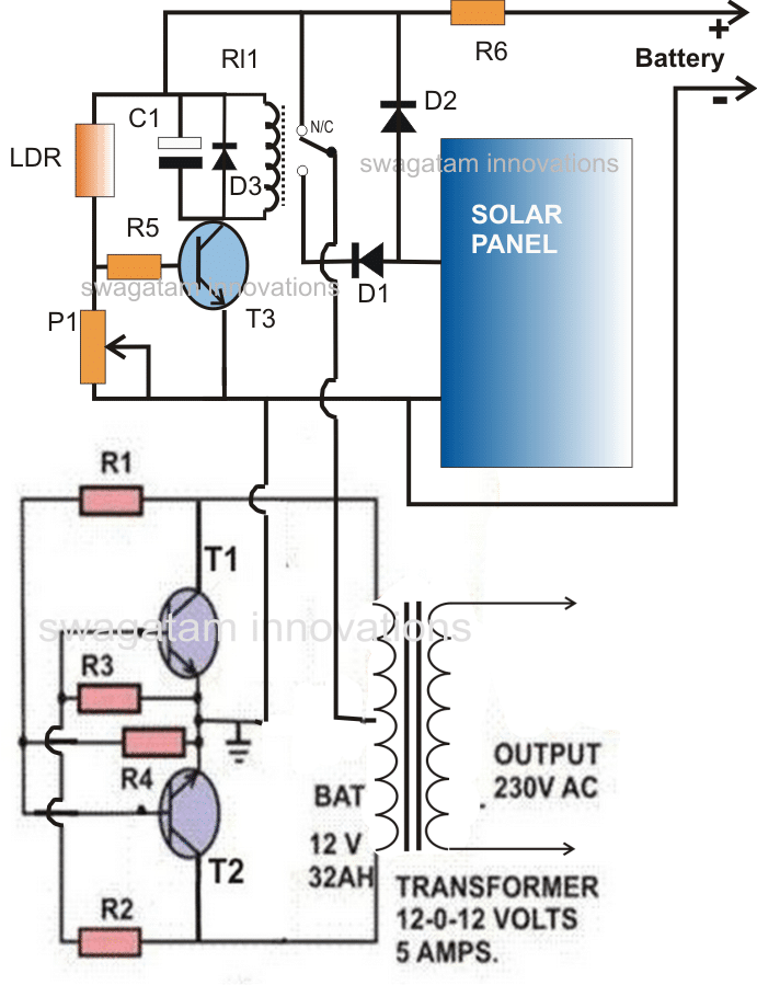
The circuit mainly consists of two stages viz: a simple inverter, and the automatic relay changeover.
During day time for so long the sun light remains reasonably strong, the panel voltage is used for charging the battery and also for powering the inverter via the relay changeover contacts.
The automatic changeover circuit preset is set such that the associated relay trips OFF when the panel voltage falls below 13 volts.
The above action disconnects the solar panel from the inverter and connects the charged battery with the inverter so that the output loads continue to run using the battery power.
Circuit Operation:
Resistors R1, R2, R3, R4 along with T1, T2 and the transformer forms the inverter section. 12 volts applied across the center tap and the ground starts the inverter immediately, however here we do not connect the battery directly at these points, rather through a relay changeover stage.
The transistor T3 with the associated components and the relay forms the relay change over stage The LDR is kept outside the house or at a position where it can sense the day light.
The P1 preset is adjusted such that T3 just stops conducting and cuts off the relay in case the ambient light falls below a certain level, or simply when the voltage goes below 13 volts.
This obviously happens when the sun light becomes too weak and is no longer able to sustain the specified voltage levels.
However as long as sun light remains bright, the relay stays triggered, connecting the solar panel voltage directly to the inverter (transformer center tap) via the N/O contacts. Thus the inverter becomes usable through the solar panel during day time.
The solar panel is also simultaneously used for charging the battery via D2 during day time so that it charges up fully by the time it gets dusk.
The solar panel is selected such that it never generates more than 15 volts even at peak sun light levels.
The maximum power from this inverter will not be more than 60 watts.
Parts List for the proposed solar inverter with charger circuit intended for science projects.
- R1,R2 = 100 OHMS, 5 WATTS
- R3, R4 = 15 OHMS, 5 WATTS
- T1, T2 = 2N3055, MOUNTED ON SUITABLE HEATSINK
- TRANSFORMER = 9-0-9V, 3 TO 10 AMPS
- R5 = 10K
- R6 = 0.1 OHMS 1 WATT
- P1 = 100K PRESET LINEAR
- D1, D2 = 6A4
- D3 = 1N4148
- T3 = BC547
- C1 = 100uF/25V
- RELAY = 9V, SPDT
- LDR = ANY STANDARD TYPE
- SOLAR PANEL = 17 VOLTS OPEN CIRCUIT, 5 AMPS SHORT CIRCUIT CURRENT.
- BATTERY = 12 V, 25 Ah



Questions & Answers
Hi Swagatam,
I have ALFA P-5000 PWM inverter bye I want to modify to MPPT, the motherboard of ALFA is 95% same as infini v2 or inverex Aerox 5.2 kw, so if install the MPPT and system board of infini to ALFA..will it work..plz guide me .. thanks
Hi Haider,
Sorry, it is difficult to suggest any modifications inside an existing commercial unit, because we do not have its full schematic..
Hello Swagatam Please can I add start capacitor to the freezer to start it?
Hi my able engineer,I am a rewinder from Nigeria I will be very happy if you can help me out with the electronics panel that I can use to power my 5000watts transformer for my own inside my house.Thanks.
Hi Azeez, What kind of electronic panel are you referring to?
Hi Daniel, Sorry i have no idea about freezers.
Please how can power freezer directly with solar inverter without battery
Is your freezer DC or AC? If it’s AC then it will need an inverter.
Great article.. Love the way you go into the details.. Do you already manufacture commercial grade Solar Inverters?
Thank you very much, glad you liked it. No, I do not manufacture solar inverters.
Pls let me know if you are interested in doing that as a start-up… We could have an offline chat.. Thanks..
Actually the circuits presented above are all basic circuits which cannot stand the market competition, so doing a start-up in this field might not work with my level of knowledge.
Good day sir, I commence your work, well done job. Sir i have tried to build what you posted but am not getting it, also i just want to beg you that pls send me details correct diagram and materials to used, i will be happy to to receive this from you. Thanks
Hi Daniel, all the circuits presented above are correct and will work perfectly, if it is built correctly.
You can try the following design which is the most popular one:
Remember to build and test the inverter and the charger stages separately.
If you have problems let me know.
Can I use one of the schematic diagram for a 24V wind turbine? will it work? . I’m a newbie to electronics and I am planning to build an inverter.
What is the wattage or current specification of the wind turbine and the inverter, If you specify these I may try to suggest a suitable option.
Dear i have searched for 2- 3 kw Inverter solar circuit direct utilize from solar in day time but not found.
if available with us share or guide want to make at home.
i have solar panel purchased already.
Dear Shambhu, please provide more specifications of the inverter, because inverter can be of many different kinds with different voltage levels.
For the Solar Inverter Using IC 4047,
Can I use a 200W panel that supplies 12V with a 12V 10AH battery to ultimately power a load at a maximum of 200 watts? Such as a TV? I want to use the entire circuit, but am not sure if I need to swap out any parts as some of them may be rated for higher than needed wattage. I am not sure if the circuit can be used for just any power rating. Thanks.
You can do that, but you won’t get full 200 watt output due to losses. You may get a maximum of 85% efficiency. But the panel output voltage should be at least 17V to charge a 12V battery. If battery is not used then the panel can be a 14V and directly connected to the inverter for the 220V conversion.
no changes in the circuit parts is required for this…
Thanks for replying. Can you link me a transformer that I could use for this? I want to make sure I order the right one. Or at least what should I search for exactly.
For a 12 V battery 200 watt inverter you will need a 9-0-9V 24 amp transformer
So I have used multiple chips now and multiple mosfets, the mosfets keep getting hot and frying until they are broken. I have no idea what is happening. I am using a 12-0-12 transformer but this wouldn’t affect the circuit right? I am so confused. The circuit worked one single time out of 50 trials, just confusing. The mosfets seem to get the hottest at the drain if that helps. I’d love to send you a picture of my circuit. I am using the 68k resistor and 0.1 uF cap.
50 are too many trials, you should have stopped at the 3rd trial.
Mosfet can blow under 3 conditions: wrong connection, extremely high drain current, avalanche current.
Assuming your connections are right, the extreme drain current can happen if the transformer current rating is higher than the mosfet can handle, or low winding voltage rating than the battery voltage, avalanche can happen for the same reason but can be prevented by adding external diodes across drain/source pins of the MOSFET.
One more reason could be your IC 4047 output? Is it oscillating? did you check the frequency?
I would suggest trying with BJTs first like TIP122 etc….if it works with BJTs then it might work with a MOSFET also.
So I made the 4047 circuit and ran into an issue. I accidentally had pin 14 of the 4047 tied to battery negative instead of positive. I powered the circuit without realizing, and one of my MOSFETs started smoking and basically fried. Do you have any idea why this happened? I am confused as to why this would affect the transistors. Thank you.
If you connected the IC with opposite polarity, then most probably your IC is shorted and blown internally, which might have caused your MOSFET to also blow….you will have to replace the IC with a new one, and always make sure to use a diode 1N4007 at the positive supply pin of all ICs, to prevent an accidental opposite polarity issue.
Can C2 be a ceramic capacitor?
I cannot find C2 in the 4047 design, are you referring to C1?
Why not a 12-0-12 transformer? Also it is very hard to find a 25A version of one of these things. I have not been able to find one on the internet.
Power Inverter transformers are generally made to order, since high current trafos are mostly not available in the market.
12-0-12 will give you 220V at 12V battery voltage, when the battery drops to 11V, the output will drop to below 200V
Good to hear from you thanks.
Swagatam,
Solar cells and solar panels have datasheets that have several plots of Isc versus Voc, with each plot at a specific level of sunlight.
It’s my understanding that to extract the maximum power, Pmp, from a solar panel, it must be operated at a point where the product of Isc and Voc is at a maximum. Isc at this point is denoted as Imp, and Voc is denoted by Vmp. These numbers shift primarily with sunlight, secondarily with temp, and maybe less with aging.
So, how specifically does an MPPT technique adjust the voltage on the panel so that it operates at Vmp and Imp? The voltage on the panel can be measured with a resistive divider and the current can can be measured by placing a small-valued resistor
in series with the bottom (normally grounded) lead.
What puzzles me is, given this information, what does the system do with it? How are the operating conditions on the panel itself changed to adjust Voc and Isc continually as the sunlight or temp change?
Thanks, Steve
Steve, the MPPT has a buck converter circuit, whose output is appropriately optimized by adjusting the PWM switching, in response to the varying Voc and Isc of the panel output
Swagatam,
Let’s put this discussion in the context of one of your circuits
in “Best 3 MPPT Solar Charge Converter Circuits” .
Pick one circuit and then I’ll have some questions about it.
Thanks, Steve
Swagatam,
I will be constructing your “Solar Converter Using IC 4047”.
I think it will be a simple yet educational introduction
to solar power system design. I’ll be using an 85W solar panel to light a 15W bulb, day and night.
In a few months, I may put together a system having a simple form of MPPT.
First, however, I’m looking to find a clear explanation of MPPT in terms of what’s measured and what’s controlled.
The solar panel’s operating voltage Vph can be observed with a resistive divider. The panel’s current Iph can be observed with a small resistor in series with the negative terminal to ground.
In fact, I’ve seen a circuit that takes these outputs into a multiplier. So, the multiplier can be used to find to find a max value of Pph =Vph x Iph. What’s not clear to me is how Pph can be used to adjust some piece of the remaining circuitry to actually achieve a maximum power operating point of the solar panel.
Ideally, I’d like a qualitative verbal explanation, i.e., in words rather than a reference to circuit details.
No problem Steve, you can go ahead with the 4047 inverter it is one of the easiest and the most reliable inverter circuits you can find.
The main function of MPPT is to ensure that there are minimum losses across the input and the output power for the load, at any instant of operation.
That said, the MPPT output power can never exceed the input power of the panel.
The second feature of an MPPT is to ensure that the load can never overload or exceed the maximum power output from the panel and the panel always works at its maximum efficiency spec.
Swagatam,
Another question on “Solar Inverter Using IC 4047” –
Two ground connections are made to the left of the ammeter.
Shouldn’t the ground immediately to the left of the ammeter be
eliminated? And shouldn’t the other ground be connected to the bottom of R3 ?
As the original schematic stands right now, the charge current limiter can’t possibly work.
Thanks, Steve
Swagatam,
WRT the “Solar Inverter Using IC 4047” –
You’re right. The placement of the grounds is OK.
I’ve put together a parts list for the circuit.
Can you give me a part number or description for the “25A diode”
that connects the high output of the solar panel
to the input of the LM 338?
Thanks, Steve
No problem Steve, you can easily get all the required details online, if you simply Google “25 Amp diode”
Swagatam,
Also, what is the purpose of switch s1 ?
When would the switch be open and when
would it be closed?
Thanks Again, Steve
Steve, the switch is for switching ON the inverter when the battery is fully charged, or during evening time, when the sunlight is no longer available and the battery is assumed to be fully charged.
Steve, the inverter is supposed to work using battery power not the panel power, therefore its negative line should be connected where it is shown in the diagram.
Can you explain why the charge current limiter can’t work? In the shown diagram the charge current has to pass through R3, which ensures that the battery charging current is appropriately controlled by the LM338
Swagatam,
In the “solar converter using IC 555”, what is the purpose of the
npn transistor whose collector is tied to the adj pin on the LM338?
Hi Steve, it is for controlling current to the battery, and ensuring a constant current supply
Hi,
I’d like to build your “solar inverter using 2N3055 transistor”.
However, I can’t find a supplier for the step-up transformer.
Can you specify a transformer part number and supplier?
Thanks,
Steve Sherman
Swagatam,
Thanks. I guess that I can use a step-down power transformer
and reverse the primary and secondary to get a step-up transformer.
Also, I’d like to suggest that future schematics include
some voltages at key points. I realize that depending on the the solar panel some of the voltages might be different. But an example case would be useful.
Sure you can do that Steve. Showing the Voltages across the various points is actually not so crucial for such simple design, since the user will already know them as per the specifications of the parts, and the stages.
For example the LM338 output is to be set for the maximum battery charge level. The voltage for the 4093 IC will be 12 V from the 7812 IC. Likewise, for a square wave inverter the voltage from the IC outputs will be 50% of the 12V supply, and so on.
If you have any specific doubt regarding the subject you can ask here, I’ll try to clarify….
Swagatam,
Thanks for your advice.
My son is a sophomore in college and has recently started working
on perovskite solar cell.
I’d like to build a dirt-simple solar power system that would use a commercial solar panel to keep a 40W bulb lit for ten hours at night.
This system would serve as an end application tutorial for my son.
So, I’m considering your “Solar Inverter using IC 555”.
I’ll keep you informed.
Thanks, Steve
Thank you Steve, and Congratulations on your son’s new endeavor! The IC 555 looks much easier so this circuit can be tried for a simple solar inverter prototype.
If you want even a simpler inverter design you can go for the first option presented in the following article:
7 Simple Inverter Circuits you can Build at Home
Swagatam,
In “Solar Inverter using IC 4047”, how is the solar panel’s
operating voltage set?
If the solar panel is allowed to operate at Voc,
then the output current will be small and little
power will be developed.
Thanks, Steve
Steve, the solar panel output (Voc) has to be a few voltage higher than the inverter operating voltage, and the current should be as required by the inverter and the load.
If the inverter wattage is 100 watt, voltage is 12V, then the solar panel can be rated at 16V and 100/12 = 8.33 amp
For higher voltage, low current panels you may require a buck converter as explained in the above article
Hi, I think you can get it from online retailers like amazon, or eBay. The specs of the transformer are 9-0-9V/10 amps, 220V or 120V
Swagatam great kudos! Pls which of the above circuits or any other simply solves my issue of 1000w inverter (even at No Load) tripping off and turns on its red fault led whenever the Sun’s intensity goes high on the solar panel connected? My mini solar setup is a 100 watts solar panel (18.5v peak) wired to a 75Ah, 12v battery bank (no charge controller) and the inverter connected to battery terminals. The inverter Works fine if Sun intensity is low or average (I guess the high sun intensity puts the input voltage out of range for the inverter to continue to work). Thanks for prompt reply.
Lawal, there are no specific rules for making a solar inverter. You can use any ordinary inverter and hook it up with an appropriately rated solar panel for the required results.
So you can use any one of the circuits from the above concepts. For 1000 watt you will need a 200 Ah battery, which will need to be charged at 20 amps. So in place of the LM338 circuit you will need to replace it with the design explained in the following article:
High Current Solar Battery Charger Circuit – 25 Amps
For controlling over-voltage you can add a simple voltage control feedback or a shunt regulator with the panel.
Sir swagatam I want to know transistor made inverter and ic inverter which is powerful
hi, or may to connect,and, how hybrid inverter ,solar panels, battery like this: that when batteries get low-automaticly turns into pole circuit and when batteries get full charge- automatically turns from pole in to off grid[from batteries]? thanks
Hi, please type “changeover” in the search box to get the required solution.
Roy, In IC based inveretr the IC works like an oscillator for driving the power output stage, if the IC is replaced with transistors it does the same and generates the frequency for the output…so basically the oscillator stage is only for generating the 50 Hz or 60 Hz frequencies it does not determine the power of the inverter…power is determined by the output MOSFeT stage.
OK sir thanks
Hi Swagatam,
Thanks for your quick response. i got the answer you gave, that the battery needed is supposed to be rated 5000Ah, clear. From the advise i take it that I need 20 solar panels of 300W each. A follow up question is, how do I upgrade the inverter power and the transformer. Please advise.
George
Hi George,
The 5000 Ah is for battery, for a solar panel it just needs to be 500 amps or may be a little higher than that. yes a 20 panel having 12V/300 watt should be sufficient.
The 500 amp will get proportionately reduced if the panel voltage specs is higher…so if the panels are 24V, amps will be reduced to 250 amps, and so on.
The same goes for the inverter. You can upgrade it by suing an appropriately rated transformer and by changing the MOSFETs that would match the specified power specs.
Thank you so very much for your response.
I will be asking related questions concerning solar energy.
Best regards
George
Hi Swagatam,
Thank you for your vast educative knowledge.
I have a solor Inverter with 1000w which produces AC 230V, with a battery of DC 12V. What should I do to the inveter to be able to turn a mortor of 8 horsepower.
Thanks George
Thanks George,
that looks impracticable. 8 Hp means 8 x 746 = approx 6000 watts. You will have to upgrade the inverter power devices and the transformer to match this awesome power, and use a battery that must be rated at 5000 Ah
Hello, can u please help with the pcb
Sorry I do not design PCBs!
hi!,sir can I use 15-0-15volt transmformer???
Hi Oliver, for a 12V battery a 15V transformer might not work optimally, it might result in a low voltage output.
thanks sir,,hope i can use 12-0-12volt transformer and how many pins has the ic4093 ?
Oliver, you can use 12-0-12V transformer if your solar panel is rated at least 17V
hi sir great work are doing. i have follow up some of your diagram. please sir if i put together this circuit the it show. will it work perfect. thanks
Hi Dominic, yes definitely it will work, for more information you can also read the following article:
https://www.homemade-circuits.com/designing-solar-inverter-tutorial/
If you have issues just let me know, I’ll try to solve it for you
hi sir great work
i am making a hybrid energy system my dc wind is 50watt and solar is 30watt 2amp . and battery is 12v and 10 amp.
and we are are using load 40watt bulb. can you please recommend me which solar inverter i should made ?? and solar inverter power etc
thnaks
Thanks Ali,
you can try the following simple inverter circuit
https://www.homemade-circuits.com/modifying-4047-ic-inverter-into-sine/
Hello sir , i want to know this circuit clearly can u explain for me clearly with circuit diagram in my mail
Hello sreejith,
It is already explained in the article, if you have any specific questions you can ask, I’ll try to help!
hi sir, if i want using this kind of inverter to operate the inductive load what component should i add or which part should i change?
Hi tommy, for that you may have to replace the square inverter section with an SPWM inverter
hi sir, if voltage supply from solar panel is more than 36v and feed into L7812cv what will happen for the invert part and the L7812CV
Hi Tommy, If it is within 40V the 7812 will handle it somehow, but above 40V it can be a problem to the IC.
For the inverter/battery section, the LM338 will drop it to the required level, but again LM338 so also rated at 40V max…so make sure your panel voltage never exceeds the 40V mark
sir can i know the function of Mosfet IRF543, IC7812 and IC4093 ?
mosfet is used for switching the transformer with battery current.
7812 for supplying constant voltage to the IC
and 4093 for creating the required oscillations and buffering for mosfet switching.
sir, i have increase the value of R1, but after i get around 95Hz then it is no Ac output.
the R1 value is 100K
Tommy, check the output with a load connected, such as a 40 watt bulb.
try increasing capacitor value slightly and check the response again
I did not understand what you meant by “no AC?” please clarify if possible.
sir i get the 230Vac and f=179Hz how can i reduce the frequency? my transformer rating is 12-0-12 @50VA
Tommy, either you can increase the value of R1 by adjusting the 100K preset or increase the value of C1 appropriately, to reduce the frequency to 50Hz
R3 = 0.7/max charging current in this case is 8 Amp
R3 = 0.7/8 = 0.0875
What is the actual resistor value of 0.0875
Thanks in Advance
It is in Ohms….0.0875 Ohms
R3 = 0.6 x 10 / 100 Battery AH (100 AH ) = 0.06 , what will be the actual resistor value
0.06 = Resistor Value ?
The unit is in Ohm…0.06 Ohm
sir what is the function for IRF543? and the max voltage will get from IRF543 is 80V~100V ?
It is IRF540, it is a mosfet, max voltage will depend on the transformer input winding rating and the PWM or the duty cycle from the N1 pot setting
Hi, Swagatam. I try to built the circuit but I am using 10-0-10V x’mer and I get the output only with 88 VAC max with adjusted R1 = 88 Ohms. Here, my question why I cannot 240VAC output is that because I am not using 24-0-24V x’mer?
Hi Tommy, by default the N1 stage will produce a fixed 50% duty cycle which implies that the output will get 50% less in voltage, to correct this you may have to use 6-0-6V trafo with a 12V battery meaning the trafo input V specs should 50% less of the battery V spec
the other option is to modify the N1 circuit with an adjustable PWM circuit, possibly I’ll try to modify it, and publish the modified version soon.
why i only can get the DC voltage at the output??
keep your meter in the AC 220V and check
Hi Swagatam,
My name is tommy from Malaysia. I wish you could help me to design a power inverter that use in rural area and the incomming source is from solar panel
and not expensive
You are welcome Tommy, I use CorelDraw for drawing my schematics..
hi sir can i know the value for the R3 R4? for the bottom side
tommy, R4 is not required so you can replace it with a jumper.
R3 = 0.7/max charging current
max charging current for lead acid batt is = 1/10th of the AH value of the battery
thx a lot swagatam majumdar
can i know which software you are use to draw the circuit??
Hi Tommy, you can use any inverter as a solar inverter, you can also use the above explained solar inverter for your purpose.
I'll include the parts list in the article for your reference.
may i know all the component name that use in the circuit?
yes you can go ahead with a 12-0-12 trafo also….in that case you won't require the 7812 IC for stepping down the voltage to the IC.
R4 can be eliminated, it's actually not required…and R3 = 0.6/charging current
charging current must be 1/10th of the battery AH rating
Hello Swagatam , how can I modify this inverter to Pure sine wave for running LCD TV and also get an output of 350 Watts
Hello vhafuwi, you can check the last diagram from the following article
https://www.homemade-circuits.com/2016/07/designing-solar-inverter-tutorial.html
How much solar panel watts is required to this inverter
Hello Swagatam,what is the maximum power I can get from this inverter if I increase the Mosfets, Battery and Trafo?
Hellu Lufono, it will be approximately equivalent to the transformer wattage…. provided the battery is able to supply the specified amount of current and voltage to the trafo.
Pls sir am knew in the circuit construction. Pls Hello me what was R1, R2 and R3 range
R1 = 100k preset
R2, R3 = 10k resistor
Pls sir what is R1, R2 and R3 in the diagram.
Sir, I am going to make HERIC Inverter in lab and i am facing a problem to choose SPWM and driver of MOSFETs. Inverter rating is 300W and 230V output. How to make SPWM. Please suggest me.
Gaurav, SPWM can be made by feeding a fast triangle wave at 200Hz and a slow triangle wave at 50Hz across the two inputs of an opamp.
the triangle waves could be extracted from the R/C junction of a 555IC astable circuit
have you uploded this 1000w inverter circuit???
what are the main components of solar inverter
if you use the solar panel to operate both battery and the inverter then you might require a high power panel, in the order of 10 to 15amps and you must use the last circuit where a transistor is connected with the IC for boosting current.
R3 will depend on the load current….initially don't use anything keep the points shorted and see the response.
hello sir thank you for you posting. but i have to ask one question than can we implement a circuit which automatically closed the input when the battery is fully charged? if yes than how?
please reply me soon i have to work on this
thanks kamiyab, you can implement it by adding an opamp to the LM338 circuit as explained in the following article:
https://www.homemade-circuits.com/2012/02/how-to-build-automatic-6-volt-12-volt.html
hi sir,
why the battery positive is connected with transformer neutral? and what will happen if I disconnect it? is that possible to use ordinary transformer instead of center tap?
Hi rishi,
what is transformer neutral? I did not understand your question.
the positive is connected with the center tap of a 9-0-9V transformer
center is a must here
sir i am trying to build a 50 watt sine wave inverter to be included in my clg major project .
can u please direct me towards appropriate designs .
i would really appreciate if u could help me.
Akshay, sine wave inverter can be difficult for a newcomer in the field. so I won't recommend it to you, an easier option is presented in the this article:
https://www.homemade-circuits.com/2012/02/how-to-make-simplest-inverter-circuit.html
the design at the end of the article will provide a sinewave kind of output which could be suitable for most electronic appliances.
Yes
Yes, solar panel inverter without transformer.
sir, i am elect elect engr, i have been into inverter and ups more than 10 years but i want to have more idea on SOLAR SYSTEM, PLEASE CAN I GO ABOUT THIS? to be an installer, designer.etc
Agbuna, you can try the above circuits, but these are very basic designs and therefore not so efficient…
Thank you for sharing this, it’s very enlightening. What affects efficiency? Is an H bright design more efficient than these basic circuits?
Thank you, yes an H bridge is always more efficient but require a bit critical optimization and regulation procedures.
Hello sir
My name is Abdulrahim Muhammad Umar from Nigeria.
Please sir I need your help I want to cunstruct a solar inverter for water pump without battery and the water pump is 2hp 230volt 50Ha.
Please sir
Help me with the correct circuit digram
Hello Abdulrhim, you can try the following design:
But you cannot build this design successfully unless you have some previous experience in building power inverters.
you can use a 0.022 ohm, 5 watt resistor
sir, for 250ah battery what resistor value and watts for r3 and emiter resistor? thank you very much sir and god bless you sir
I have used LM338 to step down the voltage, but it's not the efficient way of doing it, you can use a buck converter instead.
solar intensity is not always the same.
what could be done for this?
Hello swagatam ji….can you please send me working circuit of 1kw inverters….if possible can you please send me transformer less one too….my mail is : thuranga.rao@gmail.com
you can use a 4047 IC circuit and connect the following given output stage with it to get any amount of power as per your preference:
https://www.homemade-circuits.com/2014/10/upgrading-low-power-inverter-to-high.html
Is it possible to use a transformer having a rating of only 2 Amps in this circuit?
yes it's possible but a 2amp trafo will offer not more than 25 watts of power output
hai swagatam ,
i need to convert dc 700 volt to ac and reduce it to low voltage for battery charging ,because i have panels connected series for agri 5 hp solor pumpset which is run by solor vfd ,so i dont want to disturb the connection and i want to keep changeover switch inbetween dc bus voltage from panels and use it to home by ups when not in agri us
….if you have doubts, please feel free to ask me…
Hi Shiva,
you can try the following design and modify the specs accordingly for your application:
https://www.homemade-circuits.com/2015/05/smps-mains-voltage-stabilizer-circuit.html
Hi Swagatam,
My name is Benjamin from Malaysia. I wish you could help me to design a power pack with the 230V AC input with less than 5AMPs and output 9.6V dc.
Hi Benjamin, I guess you want to make an SMPS 9.6V, 5 amp circuit, right?
You can try the following circuit:
https://www.homemade-circuits.com/2012/03/how-to-make-simple-12-v-1-amp-switch.html
Sir what is the value of diode across mosfet
you can use 1N5408 for the diodes across the mosfet…
Sir i want to know can i iuse 12-0-12 transformer in the circuit i am using a battery of 12v& 7.2A. also sir i want to know each and every component and how it works
sir i want to ask what isthe valiue of resistors used some of them are not specifeid ,also i want to know can lm 317 be used in place of lm338
Shantanu, are you referring to the LM338 R3/R4 resistors? these must be calculated using the following formula:
R3 = (0.6×10)/batteryAH
R4 = 2 x R3
R3 at the top can be simply a 10k resistor
if your battery AH is less than 10AH then 317 will do.
Hello sir,
Please give me your contact number. i want to purchase the solar inverter of 1000w capacity.
Hi, please specify the wattage of the unit so that I can calculate the required data.
Hi,
what rating solar panels will be required to run a 215 Ltrs (5 star rated) refrigerator, also the tell the rating of supporting inverter.
good idea
Hi Swagatam, I wanted to seek your opinion about Solar power usage –
Scenario is: I want to install 10Kv Solar system at my place without using any batteries, it should work when the day starts and entire load should switch over to Solar power, once its dusk the system should fall back to normal electricity supply, the problem I can think off is that entire 10Kv may not be produced/used always and sometimes I might just use about 1-2 kv only and rest might be passed over to grid which can cause damage to lineman working (as they might think lines are off), can you please suggest a solution to this problem or a circuit that best fulfills my problem.
Hi Gopal,
I think you can keep the inverter power isolated from the home grid line using a DPDT relay.
This relay may be controlled through the solar panel voltage itself or a simple light activated switch.
So, as long as the solar panel receives the require sunlight, the relay stays activated keeping the inverter isolated from grid and your home wiring connected with the inverter, while during night when the solar panel shuts off, the relay connects your home wiring back to grid mains.
I am designing a boost converter for my solar project (24V to 230V,20A) please can u suggest a circuit with proper values
you can try the folowing design:
https://www.homemade-circuits.com/2013/06/universal-ic-555-buck-boost-circuit.html
for getting 220v @ 20amp, your 24v input must be rated at 200 amps
I need to understand the circuit properly. What should I do?
sir,
this is kumaran, previous i request "circuit of 500watt (125wattX4 panel) solar panel controller circuit with 150ah tall tubular lead acid battery charger"
I mentioned my solar panel details,
*max. power -Pmax-125wp
*Voltage @ max. power -Vmax-17.7v
*current @max. power -imax – 7.06A
*Open circuit voltage-Vocv -21.4v
*short circuit current – i scv – 7.98A
*tolerance – T – +- 5%
*Max. system voltage -v – 1000V
regards
kumaran
please check the last circuit given in the following link, you can use it for the said purpose, adjust P1 to 14.4V for charging a 12V battery.
https://www.homemade-circuits.com/2012/05/make-this-voltage-stabilizer-circuit.html
hello sir,
i am kumaran, i need a circuit of 500watt (125wattX4 panel) solar panel controller circuit with 150ah lead acid battery charger
thanking you
regards
Kumaran
hello kumaran,
please provide the peak voltage rating of the panel.
I have all these circuits published in my blog separately which can be added here, however if we add everything the design will become too complicated for small hobbyists, therefore the external ad-ons can be integrated as per individual preferences.
connect a 1uF/400v capacitor across the output, this will reduce the output to some extent.
Hi,
this is nice site.
I am staying in hyd.
my mail id: madhu.battula@gmail.com
where can get the leds? which you have mentioned in led tube light.
thank you
Hi, you can the LEDs from any electronic spare part retailer in Hyderabad.