• Skip to main content
  • Skip to primary sidebar

Homemade Circuit Projects

Get free circuit help 24/7

Circuits for Beginners | Basic Circuits | LED Driver | Hobby Circuits | Transistor Circuits

New-Projects | Privacy Policy | About us | Contact | Disclaimer | Copyright

Home » Inverter Circuits » 500 Watt Inverter Circuit with Battery Charger

500 Watt Inverter Circuit with Battery Charger

Last Updated on August 3, 2020 by Swagatam 218 Comments

In this post we will comprehensively discuss how to build a 500 watt inverter circuit with an integrated automatic battery charger stage.

Further in the article we will also learn how to upgrade the system for higher loads and how to enhance ot into a pure sine wave version.

This 500 watt power inverter will convert a 12 V DC or 24 V DC from a lead acid battery to 220 V or 120 V AC, which can be used for powering all types of loads, right from CFL lights, LED bulbs, fans, heaters, motors, pumps, mixers, computer, and so on.

Basic Design

An inverter can be designed in many different ways, simply by replacing the oscillator stage with another type of oscillator stage, as per user preference.

The oscillator stage is basically an astable multivibrator which could be using ICs or transistors.

Although an astable based oscillator can be designed in various ways, we will use the IC 4047 option here since it is a versatile, accurate and a specialized astable chip designed specifically for applications like inverers.
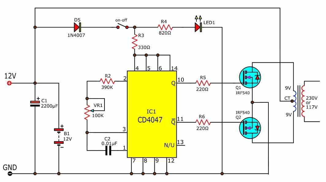
Using IC 4047

Making any inverter using the IC 4047 is probably the most recommended option due to high accuracy and readability of the IC. The device is a versatile oscillator IC which provides a dual push pull or flip flop output across its pin10 and pin11, and also a single square wave output at pin13.

BASIC CIRCUIT

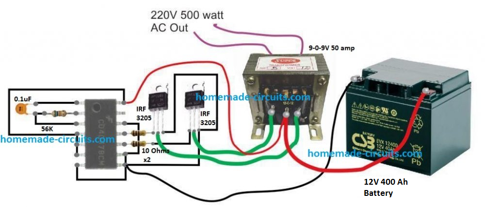
A basic 500 watt inverter with a square wave output can be as simple as above to build. However, to upgrade it with a battery charger we may have to employ a charger transformer rated appropriately as per the battery specifications.

Before learning the charger configuration let's first get acquainted with the battery specification required for this project.

From one of our previous post we know that the more appropriate charging and discharging rate of a lead acid battery should be at 0.1C rate or at a supply current that's 10 time less than the battery Ah rating. This implies that to get a minimum of 7 hours back up at 500 watt load, the battery Ah could be calculated in the following manner

Operational current required for a 500 watt load from a 12V battery will be 500 / 12 = 41 Amps approximately

This 41 amps needs to last for 7 hours, implies that the battery Ah must be = 41 x 7 = 287 Ah. However, in real life this will will need to be at least 350 Ah.

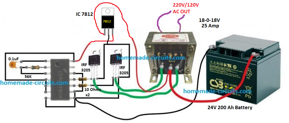
For a 24 V battery this may come down to 50% less at 200 Ah. This is exactly why a higher operational voltage is always advised as the wattage rating of the inverter gets on the higher side.

Using 24 V Battery

In order to keep the battery and the transformer size smaller and cables thinner, you may want to use a 24 V battery for operainf the proposed 500 watt design.

The basic design would remain as is, except a 7812 IC added to the IC 4047 circuit, as shown below:

Schematic Diagram

Battery Charger

To keep the design simple yet effective, I have avoided the use an automatic cut off for the battery charger here, and have also ensured a single common transformer is used for the inverter and the charger operations.

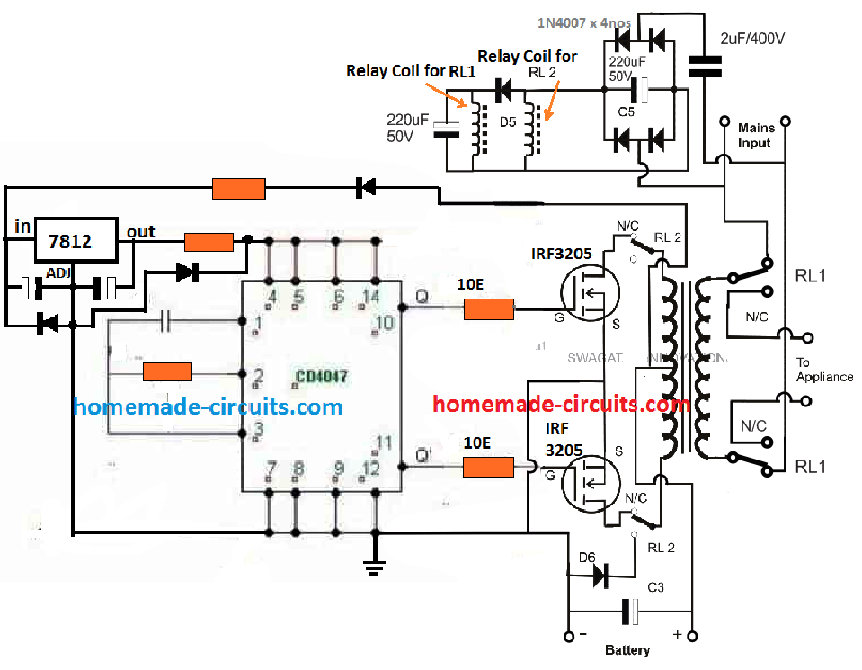
The complete circuit diagram for the proposed 500 watt inverter with battery charger can be seen below:

The same concept has been already elaborately discussed in one of the other related posts, which you can refer to for additional information.

Basically, the inverter uses the same transformer for charging the battery and for converting the battery power to 220 V AC output. The operation is implemented through a relay changeover network, that alternately changes the transformer winding to charging mode and inverter mode.

How it Works

When grid mains AC is not available, the relay contacts are positioned at their respective N/C points (normally closed). This connects the drains of the MOSFETs with the transformer primary, and the appliances or the load connect with the secondary of the transformer.

The unit gets into inverter mode and begins generating the required 220V AC or 120 V AC from the battery.

The relay coils are powered from a simple crude transformerless (capacitive) power supply circuit using a 2uF / 400V dropping capacitor.

The supply is not required to be stabilized or well regulated because the load is in the form of the relay coils which are quite heavy duty and will easily withstand the switch ON surge from the 2uF capacitor.

The coil for RL1 relay which controls the mains AC side of the transformer can be seen connected before a blocking diode, while the coil of RL2 which controls the MOSFET side is positioned after the diode and in parallel to a large capacitor.

This is intentionally done to create a small delay effect for RL2, or to ensure RL1 switches ON and OFF prior to RL2. This is for safety concerns, and to ensure that the MOSFETs are never subjected to the reverse charging supply whenever the relay moves from inverter mode to charging mode.
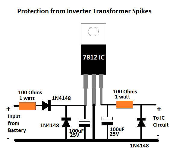
Safety Suggestions

As we know, in any inverter circuit the transformer works like an heavy inductive load. When such a heavy inductive load is switched with a frequency, it's bound to generate a massive amount current spikes which may be potentially dangerous for the sensitive electronics and the involved ICs.

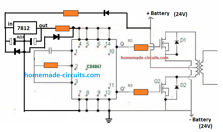
To ensure proper safety to the electronic stage, it may be important to modify the 7812 section in the following manner:

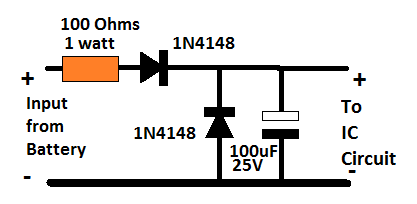
For a 12V application, you can reduce the above spike protection circuit to the following version:

Battery, MOSFET and Transformer Determine the Wattage

We have discussed this many times through different posts that it is the transformer, the battery, and the MOSFET ratings that actually decide how much power an inverter can produce.

We have already talked about the battery calculations in the previous paragraphs, now let's see how the transformer can be calculated for complementing the required power output.

It is actually very simple. Since the voltage is supposed to be 24 V, and power 500 watts, dividing 500 with 24 gives 20.83 amps. Meaning the transformer amp rating must be above 21 amps, preferably up to 25 amps.

However, since we are using the same transformer for both charging and inverter modes, we have to select the voltage in such a way that it suits both the operations optimally.

A 20-0-20 V for the primary side appears to be a good compromise, in fact it is the ideally suited rating for the overall working of the inverter across both the modes.

Since, only one half winding is used for charging the battery, the 20 V RMS rating of the transformer can be used for getting a 20 x 1.41 = 28.2 V peak Dc across the battery with the help of the associated filter capacitor connected across the battery terminals. This voltage will charge the battery at good rate and at the correct speed.

In the inverter mode, when the battery is at around 26 V, will allow the inverter output to be at 24/26 = 220 / Out

Out = 238 V

This looks a healthy output while th battery is optimally charged, and even when the battery drops to 23 V, the output can be expected to sustain a healthy 210V

Calculating MOSFET: MOSFETs basically work like switches that must not burn while switching rated amount of current, and also must not heat up due to increased resistance to switching currents.

To satisfy the above aspects, we have to make sure that the current handling capacity or the ID spec of the MOSFET is well over 25 amps for our 500 watt inverter. Also to prevent high dissipation and inefficient switching the MOSFET's RDSon spec must be as low as possible.

The device shown in the diagram is IRF3205, which has an ID of 110 amp and RDSon of 8 milliohms (0.008 Ohms), which actually looks quite impressive and perfectly suitable for this inverter project.

Parts List

To make the above 500 watt inverter with battery charger, you will need the following bill of materials:

  • IC 4047 = 1
  • Resistors
  • 56K = 1
  • 10 ohms = 2
  • Capacitor 0.1uF = 1
  • Capacitor 4700uF / 50 V = 1 (across the battery terminals)
  • MOSFETs IRF3205 = 2
  • Diode 20 amp = 1
  • Heatsink for the MOSFETs = Large Finned Type
  • Blocking Diode Across MOSFETs Drain/Source = 1N5402 (Please connect them across drain/source of each MOSFET for added protection against reverse EMF from the transformer primary. Cathode will go to the drain pin.
  • Relay DPDT 40 amp = 2 nos

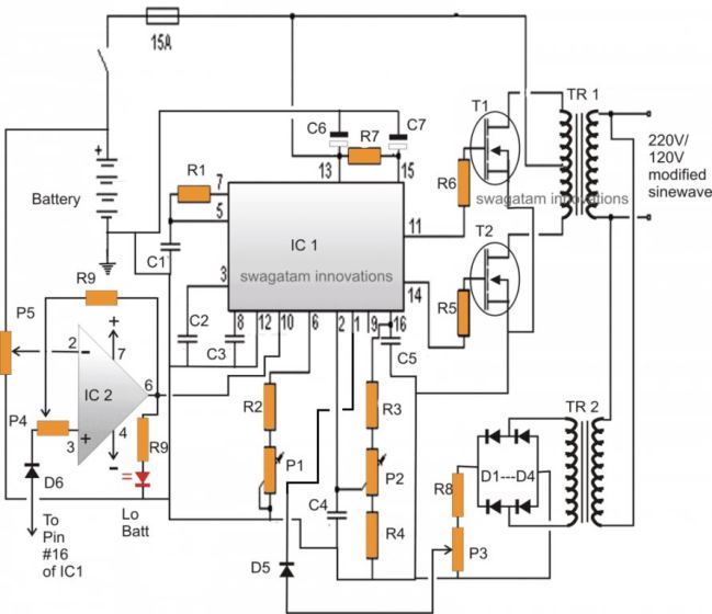
Upgrading to Modified Sinewave Inverter

The square wave version discussed above can be effectively converted into a modified sinewave 500 watt inverter circuit with much improved output waveform.

For this we use the age old IC 555 and IC 741 combination for manufacturing the intended sine waveform.

The complete circuit with battery charger is given below:

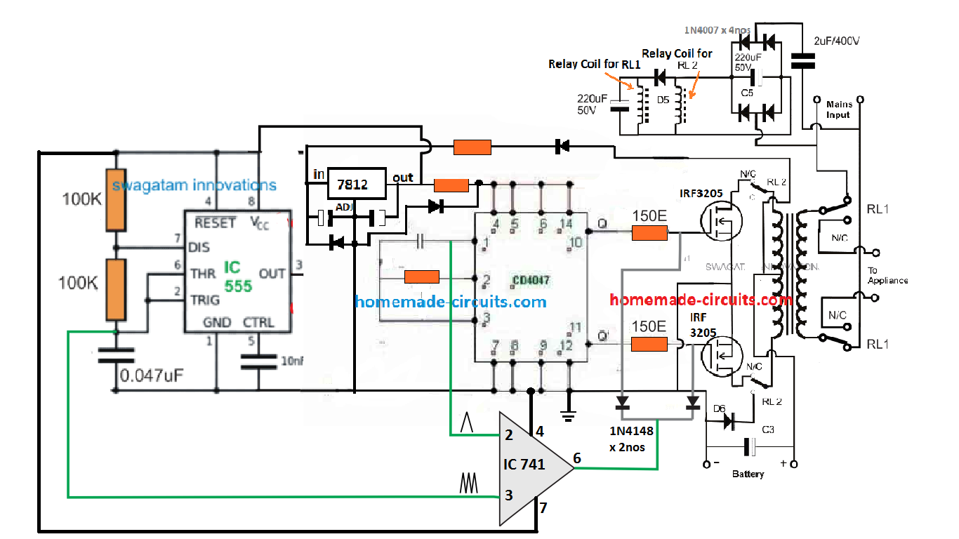
The idea is the same which has been applied in a few of the other sinewave inverter designs in this website. It is to chop the gate of the power MOSFETs with calculated SPWM so that a replicated high current SPWM is oscillated across the push pull winding of the transformer primary.

The IC 741 is used as a comparator which compares two triangle waves across its two inputs. The slow base triangle wave is acquired from the IC 4047 Ct pin, while the fast triangle wave is derived from an external IC 555 astable stage. The result is a calculated SPWM at pin6 of the IC 741. This SPWM is chopped at the gates of the power MOSFETs which is switching by the transformer at the same SPWM frequency.

This results in the secondary side with a pure sinewave output (after some filtration).

Full Bridge Design

The full bridge version for the above concept ca be built using the below given configuration:

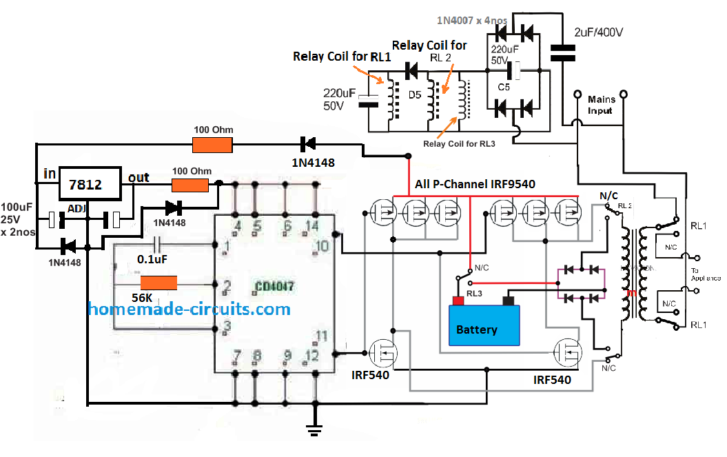
For sake simplicity, an automatic battery cut off is not included, so it is recommend to switched OFF the supply as soon as the battery voltage reaches the full charge level. Or alternatively you may add an appropriately filament bulb in series with the charging positive line of the battery, to ensure a safe charging for the battery.

If you have questions or doubts regarding the above concept, the comment box below is all yours.

You'll also like:

  • 1.  2 Cool 50 Watt Inverter Circuits for Students and Hobbyists
  • 2.  SG3525 Full Bridge Inverter Circuit
  • 3.  Grid Mains to Generator Changeover Relay Circuit
  • 4.  Simplest Full Bridge Inverter Circuit
  • 5.  SPDT Relay Switch Circuit using Triac
  • 6.  How to Make a Simple 200 VA, Homemade Power Inverter Circuit – Square Wave Concept

About Swagatam

I am an electronic engineer (dipIETE ), hobbyist, inventor, schematic/PCB designer, manufacturer. I am also the founder of the website: https://www.homemade-circuits.com/, where I love sharing my innovative circuit ideas and tutorials.
If you have any circuit related query, you may interact through comments, I'll be most happy to help!

Subscribe2


Reader Interactions

Comments

    Your Comments are too Valuable! But please see that they are related to the above article, and are not off-topic! Cancel reply

    Your email address will not be published. Required fields are marked *

  1. Juan Carlos Bonavota says

    I liked the circuit. I only wish it had a power supply for its regulation both in frequency and in output voltage. Thank you very much

    Reply
    • Swagatam says

      Thank you, if possible I’ll try to update the details in the article.

      Reply
      • khoram riyahi says

        hi dear Mr Swagatam
        i prepare circuit contains 4047 and 3205 and 500watt transformer test with 12 volt adapter 3A is and 9 watt load OK but connecting it to battery causes MOSFET connected to pin 10 of 4047 (via) 10 ohm without load broken . please inform me what is wrong.
        bet regards ; KHORAM RIYAHI

        Reply
        • Swagatam says

          Hi Khoram, it could be due to high current reverse spike from the transformer.

          Please go through the following article, and try to include all the measures that is indicated in all the single MOSFET diagrams.

          https://www.homemade-circuits.com/mosfet-protection-basics-explained-is/

          Also for the IC 4047 did you apply the mentioned protections. Make sure to apply at least the following:

          https://www.homemade-circuits.com/wp-content/uploads/2019/11/spike-protection-1.png

          Reply
        • riyahi says

          Dear Swagatam
          is there any limitation for battery power cable and power line because of transformer harmonic radiation.
          best regards
          riyahi

          Reply
          • Swagatam says

            Hello Riyahi, I am sorry, I have not yet investigated this issue, so not sure about the facts!

            Reply
            • khoram riyahi says

              hello Mr Swagatam :
              i designed a 12-012 to 220 volt (500 w) for inverter but practically it is 12-0-11.5 volt has it any effect on 3205 mosfet
              thanks very match. riyahi

              Reply
              • Swagatam says

                Hello riyahi, the difference in voltage across the transformer winding will have no effect on the mosfet behavior. You can use it safely…

                Reply
      • faith says

        Pls sir can u give me the pure diagram of the inverter with battery charging. Pls dont use symbols I didn’t understand it well

        Reply
      • Morris says

        Hello is the 2nd last circuit in this article best to use in my shop as backup when there is a power grid failure? Two, can I u irf3205 being it’s an inverter charger? Thanks

        Reply
        • Swagatam says

          You can use it but only if you have understood the design perfectly.You can use IRF3205 for the inverter

          Reply
          • MORRIS says

            And can I use two 4 irf3205 or 2 are just enough for the the 500w inverter charger?

            Reply
            • Swagatam says

              I think 4 will be better, 2 on each side, and mounted on large heatsinks. Make sure to put protection diodes across darin/source of the parallel mosfets. One common diode across each parallel set will be enough.

              Reply
              • MORRIS says

                Ok sir. Now with 2nd last modified inverter sine wave inverter charger in this article. If u compare it with the second circuit in your 7 modified sine wave inverter in the other article which one is best and efficient I can use in my shop?

                Reply
                • Swagatam says

                  The second last circuit above is more efficient but more complex to build.

                  Reply
                  • MORRIS says

                    Ok sir, but as an expert in this field if I avoid the charger part of this circuit in ths article as use it as an inverter alone. It still stands the best compared to the first two circuits in the 7 modified sine wave inverter? Advise sir, I want to pick one. Thanks in advance.

                    Reply
                    • Swagatam says

                      Morris, yes the second last circuit is more efficient but you will require an oscilloscope for testing the waveform. In the 7 modified article, a oscilloscope may not be required.

                    • MORRIS says

                      Sir I don’t have oscilloscope in my shop. Can i jst use it pliz or switch to the first two circuit in the 7 modified sine wave inverter? Advise

                    • Swagatam says

                      Without an oscilloscope it is not possible to complete the second last design, in that you case you can build the second design from the 7 modified article. Make sure to check the video to see the waveform details.

                    • MORRIS says

                      So if I make it the way it is to charge the battery I still need an oscilloscope to verify its vave form?

                    • Swagatam says

                      oscilloscope has nothing to do with battery charging, the scope is needed only to verify the inverter output waveform

                    • MORRIS says

                      Ok sir. Let me just build it and use it in my shop as more efficient one as you told me. Hope it will perform well. Thank u very much

                    • Swagatam says

                      Sure, no problem.

      • MORRIS says

        Hello my lecturer, I just want u to help me abit on the inverter circuit. My customer brought me an inverter charger 800 VA and it’s motherboard is completely damaged. Can u refer me to one of your sine wave inverter charger that I can replace with it pliz. 12v 800VA I beg

        Reply
        • Swagatam says

          Hello Morris, most of the inverters circuits explained in this blog use center tap transformer which cannot be replaced with the mother board of your inverter, unless your inverter is also a center tap type.

          Reply
          • MORRIS says

            Ok my transformer is a center tap wire can I use the second last modified sine wave circuit and use 8 mosfet output to match the transformer size and get the best output wattage or that 800VA

            Reply
            • Swagatam says

              Yes you can do that, but build it step wise. First build the basic inverter, test and confirm, then add the sine wave section, test and confirm and then finally build the battery charger stage, again test and confirm. You will need an oscilloscope for all this.

              Reply
              • MORRIS says

                But sir i don’t an oscilloscope, if build it the way u drew it as I can see without that oscilloscope will it work? Secondly, if not can I use the the second circuit in your 7 modified sine wave inverter and use the 8 MOSFETs to get the equivalent 800VA. The inverter is luminous 12v 800va from India. Advise

                Reply
                • Swagatam says

                  Without oscilloscope how will you test the waveforms?….please do not build without an oscilloscope.

                  Reply
                  • MORRIS says

                    Thanks for your response sir, I appreciate a lot how u advise. Lastly, in this post the last circuit using transformer without center tap wire is it also a modified sine wave inverter at just an ordinary but does that require an oscilloscope to verify its output wave form? That’s all I have sir thanks in advance.

                    Reply
                    • Swagatam says

                      You are welcome Morris, the last circuit is an ordinary square wave inverter not a modified one. Oscilloscope is recommended for all inverters, to ensure that the waveform is correctly verified.

          • MORRIS says

            And is the second circuit in the 7 modified sine wave inverter good to use if I use 8 output MOSFETs to match the size of the transformer and get altleast 800va or equivalent the i look for a separate charge? Advice I beg. Thanks.

            Reply
            • Swagatam says

              yes the second circuit is good, will give you a decent modified sine wave which is quite equal to a pure sine wave. Commercial inverters never use center tap transformer for their inverter designs, as far as I know.

              Reply
              • MORRIS says

                Ok sir. So for the lighting and tv’s it will work perfectly…the second modified sine wave inverter? So I will use 10pcs if MOSFETs…….the ones in ths damaged motherboard (55nf06)? Many thanks sir.

                Reply
                • Swagatam says

                  You will have to connect a few 1uF/400V capacitors at the output of the transformer to get a pure sine wave like response which will suit most equipment. You can use 10 mosfets in parallel on ech channel.

                  Reply
  2. Vikram says

    Is 24v battery is available

    Reply
  3. Evans says

    Hi,I like the design. What can be done to the circuit so that I can use a two wire transformer at the primary side and also instead of using the relays I just use the same mosfets for inverter and battery charging? I’ll appreciate a schematic diagram if possible.

    Reply
    • Swagatam says

      Hi, I’ll try to update it soon

      Reply
      • Evans says

        Will appreciate

        Reply
      • Evans mworeh says

        Hello sir swagatam,how did it go,did you find anything good for an update about an inverter circuit diagram using a transformer without centre tap?

        Reply
        • Swagatam says

          Hi Evans, I have updated a full bridge version at the end of the post. You can check it out…

          Reply
          • Amar says

            Sir pls upload current source inverter circuit and design configuration of it.

            Reply
            • Swagatam says

              I will surely try…

              Reply
          • Evans mworeh says

            Thank you sir for your kindness,now my other questions are;
            1. Can we use N channel mosfets only with the same circuit,any update please? Coz with high currents, I will be forced to use a big number of p channel mosfets which Leeds to high cost and space limitations.
            2. What could be the current ratings of RL 2 & RL 3 if for instance I built a 24vdc/220vac/6000w inverter?

            Reply
            • Swagatam says

              Evans, N-channel cannot be used without specialized ICs or a bootstrapping network

              Reply
            • Evans mworeh says

              Thank you sir for your response. So if I integrate a boostraping network then can use cd4047 as the oscillator? True or not? Any clarifications?

              Reply
              • Swagatam says

                It is possible with bootstrapping introduced with any oscillator.

                Reply
            • Evans mworeh says

              Sorry had a typing error,I meant cd4047

              Reply
  4. Andrew says

    excellent design

    Reply
  5. Andrew says

    I really appreciate this effort.
    Am new in this website and am always looking forward to understanding how a smps circuit oscillates, cause am a 17yr old beginner in electronics

    Reply
    • Swagatam says

      Thank you, I appreciate your interest…keep up the good work

      Reply
  6. Martin says

    I’ve been looking at various inverter circuit designs on the ‘net and youtube. You have done a very good job explaining your circuits and detailing how they work. As you know power inverters can be pricey for anything 500 watts and above, so your designs now seem obtainable to actually making my own.
    What would be required to build a 2000w or 5000w power inverters? Does your circuit design change?
    How would you go about calculating the components specs for a these higher wattage inverters?
    Thank you for posting your circuits and your comprehensive yet well written explanation.
    -Martin

    Reply
    • Swagatam says

      Glad you liked it, I have explained the process of calculating the transformer and the MOSfET for upgrading the inverter to any desired power level.

      Reply
  7. Loydiel says

    can I have the layout in Pcb of the modified sine wave inverter circuit?
    and what is the orange one in the circuit represents?

    Reply
  8. Bios says

    Hello Sir I have 7805ic and IRF 540 mosfet can I use it to make this inverter?

    Reply
    • Swagatam says

      Bios, 7805 will not work, you will have to use 7812, IRF540 can be tried, it might work, but mount them on large heatsinks

      Reply
  9. Evans mworeh says

    Hi engineers,I have done this project is good,I even went further ahead by making it an automatic inverter charger. My problem is that my batteries don’t get charged fully since inverters with pwm usually have their transformer voltages halved or 2/3 of the same,any help on how I can improve the charging speed will be appreciated.

    Reply
    • Swagatam says

      Thank you Evans, I have already addressed this issue in the article, under battery MOSFET, transformer selection….

      Reply
  10. lloydcruspero says

    hi sir, can you help me how to make a 500 watts inverter, 12v DC to 220v AC, 60H, and modified square waves? can you make a circuit for me and its layout on pcb?

    Reply
    • Swagatam says

      Hi lloyd, you can try the following concept

      https://www.homemade-circuits.com/1500-watt-pwm-sinewave-inverter-circuit/

      Reply
  11. yusuf-freeman abdussalam says

    good evening sir,i would like to know the formulas for calculating ic 4047 frequency

    Reply
    • Swagatam says

      Yusuf, you can refer to this article:

      https://www.homemade-circuits.com/ic-4047-datasheet-pinouts-application/

      Reply
  12. Noel says

    Hi
    I need a protection circuit that will keep an appliance switched off during load shedding and only switch on when the power comes back on and is stable at 240v.
    Kind regards.

    Reply
    • Swagatam says

      Hi, you can try the concept presented in the following article

      https://www.homemade-circuits.com/mains-high-low-voltage-protection/

      Reply
      • Noel says

        Hi
        Thanks for the reply appreciate it. Our line voltage is 240v and when we have load shedding it switches back on with over 300v. I need a circuit that will switch the appliances back on when the voltage stabilizes at 240v.
        Regards

        Reply
        • Swagatam says

          Hi, the linked circuit will do exactly that! It will never switch ON the appliance with the wrong voltage

          Reply
  13. Amar says

    I have request to you sir, pls upload configuration and design of current source inverter

    Reply
    • Swagatam says

      Thank you Amar, I am studying it, and if possible I’ll post a related article soon.

      Reply
      • K GOPI SANKAR says

        Sir i have 3kw /400v Dc on-grid Solar system… when grid power switches off during peak hours of sunshine ongrid solar also switches off.. so energy from solar system getting wasted…so during this switched off time can we have another solar inverter without battery system to run atleast 2000w power system.. Night i don’t need power

        Reply
        • Swagatam says

          Yes you can use the solar power by diverting it through a relay changeover. This relay should be powered from grid voltage, so while grid is available, the relay contacts keep the external inverter disconnected from the solar power. When the grid fails, the relay contacts switch over and connect the external inverter with the solar panel.

          Reply
          • K GOPI SANKAR says

            Thank you somuch for your Replay Sir.. without battery can i use solar energy directly .. just by converting to 220v AC from 3kw..400v DC

            Reply
            • Swagatam says

              Hi K Gopi, yes that may be possible if the transformer is correctly designed for converting the 400 V into 220 V

              Reply
  14. Akande says

    Please I need answers because I wanna couple a 130w solar panel with 650VA UPS, will this work sir

    Reply
  15. K GOPI SANKAR says

    Thank you so so much for your reply sir.. Have to finally get a jem in electronic field who solves the problems with efficiency..

    Reply
    • Swagatam says

      You are welcome KGopi

      Reply
  16. Techcrazy55 says

    Very clean and straight forward project i would like to design, But then how can i add an overload protection to practically work wit this project, Thanks Swagatam.

    Reply
    • Swagatam says

      Thank you, you can add the following concept for overload protection:

      https://www.homemade-circuits.com/low-battery-cut-off-and-overload/

      Reply
  17. Sreenivasulu Dammu says

    swagatam sir i want 12v dc 1000w or 1200w power inverter ckt diagrams.

    Reply
    • Swagatam says

      Sree, you can try any inverter design from this website, and upgrade it as per the details presented in this article:

      https://www.homemade-circuits.com/upgrading-low-power-inverter-to-high/

      Reply
  18. Eric maduku says

    Thanks for your good works. Can I add more 3205 mosfets for greater wattage? Thanks

    Reply
    • Swagatam says

      yes you can, it is the MOSFETs, the battery and the transformer that decide the power output.

      Reply
  19. Sidaray says

    Hi Sir, It’s awesome explanation but I need to know, How we will come to know whether battery charged fully, Is there any led indication?
    Thanks
    Sidaray

    Reply
    • Swagatam says

      Thanks Sidaray, the simplest way is to add an ammeter in series with the battery positive, when the needle nears the zero volt, it will indicate the battery is fully charged.

      Reply
  20. Ram says

    Note: sorry i posted this query in wrong topic before so posting here

    Hi Sir,

    Need your help again. You are very knowledgeable and humble person. This earth needs more like you.

    Can u tell how we can check efficiency of inverter in general understanding language without going into theory behind it. I m asking for the reason bcoz i have very old 3055 based desi inverter of 500 watt and it running excellent since 2003. Only thing is missing is battery overcharge protection but most of the time charging renaming off bcoz i have sukam mppt solar charge controller of 17amp with 300w solar panel. I do not want to upgrade it to digital microcontroller based only fur the reason old inverter never gone bad in 17 years. Only problem in these years that i had to re solder wires to some led and amp meter one time only. Please suggest ur valuable input wheather its worth to upgrade it with latest technology digital inverter…
    Images
    https://1drv.ms/u/s!AkqDWegCTCgviUoXPcC6pEByP6rt?e=H77KIy

    And one more question what is the best charging current practice ( at always 10% of battery capacity or can use low charging current. I think slow charging increase the battery life and so i use 5-7amp current only..) in case if powercut is about an hour in 24 hour. Battery i have is microteck 150ah. I understand u will be very busy but will feel happy if u reply with ur valuable input.

    Reply
    • Swagatam says

      Thanks Ram, you can check the efficiency by measuring and comparing the V x I of the input 12V supply side of the inverter and V x I of the output 220V side of the inverter.
      Best charging current for all lead acid battery is 10%, reducing below this level is not necessary as it may increase the charging time to 20 hours. But yes it will help to increase the life of the battery.

      for auto cut off at 14.2V you can try the following circuit
      inverter battery auto cut off

      Reply
      • Ram says

        Thank you 🙂

        Reply
  21. Ramaiah Thambi says

    Can I use a 100Ah inverter battery?

    Reply
    • Swagatam says

      with a 12V battery 100 ah will not produce 500 watts.

      Reply
      • shankar says

        but why sir ,VxI = 1200w theortically, but does it depends on effeciency and pf of inverter circuit.
        a new 12v 7.2Ah vrla battery does not provide enough power, my 5w ac led bulb running for 1-.5hr and battery voltage goes from 13.2v to10.7. ,
        kindly provide exact detail for 200w with required battery ah rating. lead acid

        Reply
        • Swagatam says

          It is because Lead acid batteries are not designed to be discharged at their full Ah rate, they must be discharged at 10% or maximum 20 % of their Ah rate.

          You can get more info on this here

          Lead Acid Battery Charger Circuits

          Reply
        • Laundrel says

          Can I use 9V battery?

          Reply
          • Swagatam says

            No!

            Reply
        • MBITCHOU BONAS says

          Good morning and thanks for these inverter circuit diagrams. I realized the second circuit (inverter using 24V battery), but anytime i switch of the circuit, at least one transistor IRF3205 will be destroyed. I have replaced the transistor many times but i still have the same problème. I have added diode berween the D and S terminals, but the problem remains.
          Thanks

          Reply
          • Swagatam says

            Hello, I have checked the 4047 based inverter using IRF540 mosfets, and it worked perfectly for me with a 100 watt load. There are three basic reasons for a mosfet getting burned. 1) if the mosfet is not original, 2) mosfet does not have basic protections 3) Sudden high current surge across drain and source.

            The sudden high current situation can be corrected by initially keeping the center tap of the transformer disconnected from the battery supply. Start by powering the IC circuit first, and confirm the frequency output from the IC. Once the frequency output is confirmed, connect the transformer center tap with the battery DC and you should find the inverter working normally. If still the mosfets burns then most probably the mosfets are not good quality.

            Reply
            • MBITCHOU BONAS says

              Thanks you once more, i think it is the quality of the MOSFET transistors as you said. Because i have done different protection methods without success. I will try with different MOSFET types. Thank you.

              Reply
              • Swagatam says

                Sure, no problem, all the best to you!

                Reply
  22. Ramaiah Thambi says

    Why don’t I get 500W with 12V 100Ah battery? I get 1200W I think. What about hot transistors?

    Reply
    • Swagatam says

      With a 100 Ah lead acid battery you shouldn’t try getting 500 watt from 12 V, if you do, you will end up destroying your battery in sometime. With 1200 watt your will destroy your battery in minutes or seconds.

      But with Li-ion it is easily possible.

      Reply
      • Ramaiah Thambi says

        Thank you very much.

        Reply
      • Ramaiah Thambi says

        Can I parallel batteries then?

        Reply
        • Swagatam says

          yes you can use batteries in parallel

          Reply
      • MANJUNATH says

        Sir You have computer ups 500VA OR 600VA CIRCUIT DIAGRAM

        Reply
        • Swagatam says

          Manjunath, sorry I do not have this circuit at this moment.

          Reply
  23. Mike Wyatt says

    I’d like to build this inverter (without the battery charger, as I plan on using solar power), but I have a problem tying up the components on the schematic with the List of Parts.
    Parts List specifies 3 resistors (10 Ohms X 2 and 56k Ohms X 1), but schematic shows 5. Likewise Parts List specifies 2 (0.1 uF and 4700 uF) capacitors, but schematic shows 3.
    Would appreciate clarification on those two issues, otherwise, everything else makes sense.
    Cheers
    Mike

    Reply
    • Swagatam says

      If the schematic shows some extra parts, there’s no harm in adding those. The parts list suggests the bare minimum parts required for building the basic 500 watt inverter, whereas the schematic shows some extra features for ensuring better safety to the circuit.

      Reply
  24. Mike Wyatt says

    Dear Swagatam
    Re 500W Inverter with charger.
    Thanks for you prompt reply. Whist I appreciate that the schematic has some additional components (for safety purposes) not shown in the List of Parts, please would you advise the values of these components, so that I can incorporate them into the circuit.
    Many thanks
    Mike

    Reply
    • Swagatam says

      Thank you Mike, the values are already given in the subsequent diagrams:
      https://www.homemade-circuits.com/wp-content/uploads/2019/11/spike-protection.png

      all the resistors are 1/4 watt 5% CFR, capacitors have voltage rating two times more than the battery voltage.

      Reply
  25. George C Nwoche says

    Please if one wants to construct a 3kva center tap transformer, what will be the size of the copper wire and the number of turns for 240vs.

    Reply
  26. Ravi Kumar says

    Dear Sir,
    I am looking for a sine wave inverter circuit with 48V/72V to 440VAC ( two individual windings of 0-230 with phase shift capacitors also serves) of 2KVA with a relay (Invertor on mode) on technology transfer basis.
    This can be based on arduino/pic/sg3524.

    Reply
    • Swagatam says

      Dear Ravi, Sorry, I do not have the sufficient information regarding the specified inverter design, at this moment.

      Reply
      • Felix says

        Good day sir, please what are the requirement for designing a 3000watt inverter.

        Reply
        • Swagatam says

          Hi Felix, for upgrading to higher wattage, you only have to add more MOSFETs in parallel, increase supply voltage to the transformer up to 48 V 70 amps, and battery up to 48 V 500 Ah

          Reply
  27. OGUNFESOLA KEHINDE says

    Sir, help me with the inverter battery automatic charger circuit diagram.

    Reply
    • Swagatam says

      Here’s a suitable link you may try:
      https://www.homemade-circuits.com/opamp-low-high-battery-charger/

      Reply
  28. jefson josy says

    hi sir i have certain doubts in making an inverter with some specific specification for a certain purpose.It will be really useful if i get a chance to contact you through phone or email please.

    Reply
    • Swagatam says

      Hi jefson, I can discuss only through this platform, and not through telephone or email

      Reply
      • Evans says

        Again sir,can I use this inveter to power a refrigerator?

        Reply
        • Swagatam says

          Yes if the output wattage of the inverter is calculated according to the fridge requirement

          Reply
  29. Paul Basant says

    hi Swagatam i would like to know how a ups can be transformed into a 12volt to 240volt inverter, currently when pluged just on battery it goes off automatically in 15 mins, how can i make it on continiuosly with being off automatically in 15 mins with 12volt battery use.

    Reply
    • Swagatam says

      Hi Paul, yes it can be done, by removing all the relay changeover stages and by connecting the load directly across the secondary of the transformer.

      Reply
      • Evans says

        Hi sir,I have some questions regarding the above articles.
        1. With 56k and 0.1uf capacitor, what is the output frequency?
        2. For the h bridge,you haven’t provided the down and how to configure it.
        3. Sir can you help upgrade the h bridge to use all N channel mosfets using discrete components and cd4047 as our osciliation and incorporate the spwm as in the above article.

        Thanks in advance and look forward to your response.

        Reply
        • Swagatam says

          Hi Evans, the frequency will be approximately 50 Hz, but might need some further adjustments to ensure a precise 50 Hz.
          The SPWM configuration procedure will be the same as done for the center tap version. Instead of connecting the op amp output directly with the MOSFeT gates, you can add a BjT stage, and used their bases for the SPWM chopping.
          For Nchannel H bridge I have already explained the method for SG3525 circuit, you can apply the same comcept here also.

          Reply
          • Evans says

            Sir,what kind of adjustments please? Again sir for h bridge,we got the high side and the lower side,how is the connection of the spwm?

            Reply
            • Swagatam says

              Evans, Adjustment of the 56k resistor or the capacitor value…please build the basic design first after that we will try to solve the SPWM

              Reply
  30. Taofeek says

    Let’s assume I upgraded my inverter up to 2000w, can I use it to iron my clothes, powering my electric cooker and the likes?

    Reply
    • Swagatam says

      Sure you can….

      Reply
    • Clarhem Armram says

      Dear Swagatam, I want to congratulate you for your admirable work, since today there are few people who offer their knowledge in this professional and disinterested way solely for the purpose of teaching.
      Excuse my inconvenience, maybe you can help me with the pcb layout of this inverter with 500w battery charger

      Reply
      • Swagatam says

        Thank you Clarhem, sorry I do not have the PCB details for this project, you can contact any professional PCB designer for the same, they will surely help you out with some charges.

        Reply
  31. Rajesh maurya says

    Sir how to connect wire for charging the battery(input current in battery)in shown ckt.

    Reply
  32. Emmanuel says

    Please sir, whi of the diode is the 20amp

    Reply
    • Swagatam says

      D6, near C3

      Reply
      • EMMANUEL says

        Thank you for the response sir. What of the D5 because I was thinking the initial one was for D5

        Reply
        • Swagatam says

          D5 is for the relay coil operation which can be just a 1N4148 diode, the 20 amp is for D6

          Reply
      • EMMANUEL says

        Thank you for your response sir. What of D5.
        And in the case of the transformer, is there any alternative to 20-0-20v. I am not able to get that here

        Reply
        • Swagatam says

          Transformer voltage must be lower than the battery voltage, you can try higher values also which will cause proportionate amount of reduction in the output AC

          Reply
          • EMMANUEL says

            Thank you very much sir. How do I put the indicator for the battery charger in other to know when it’s fully charged.
            Can it be charged with solar panel too?

            Reply
            • Swagatam says

              Hi Emanuel, for that you will have to connect an external circuit such as this:

              https://www.homemade-circuits.com/battery-full-charge-indicator-circuit/

              yes solar charging is also possible, if the panel is rated appropriately

              Reply
  33. EMMANUEL says

    Thank you sir. How many legs does the relay has and how many volt is it. And how many volts is the relay coil

    Reply
    • Swagatam says

      Emmanuel, you can see refer to the following article for all the info:

      How a Relay Works – How to Connect N/O, N/C Pins

      Reply
      • EMMANUEL says

        What do I do if I want to reduce that wattage. I mean instead of 500w I will like to do 200 or even 100watts

        Reply
        • Swagatam says

          reduce the wattage of the battery and the transformer accordingly….

          Reply
  34. EMMANUEL says

    I have connected the panel to the relay stage. But I don’t seems to know how many relay this diagram has. Kindly help

    Reply
    • Swagatam says

      which circuit are you referring to?

      Reply
  35. EMMANUEL says

    Thanks sir. I am referring to the diagram with battery charger

    Reply
    • Swagatam says

      There are two relays RL1, RL2

      Reply
      • Swagatam says

        Both are DPDT

        Reply
  36. EMMANUEL says

    Thank you sir

    Reply
  37. Raj maurya says

    Sir ,how to put charging input on this inverter for charging the battery.

    Reply
    • Swagatam says

      Raj, it is derived from the transformer itself and the mains input….

      Reply
  38. Felix Elizeche says

    Ing. mis saludos y agradecimientos,,,,,Pregunto…,En la parte de…….Actualización a inversor de onda sinusoidal modificada,,se podría alimentar el circuito con un Regulador de 9 volt (7809) el CD4047,,555,, 741 ya que sus alimentaciones están en rango,,,SEGUN Datasheet

    Reply
  39. Pradeep Verma says

    I want to know price of these components.

    Reply
  40. Stephen says

    I am a new learner, Please, how many pin has the relay used in the diagram?

    Reply
    • Swagatam says

      Each of the relays have 8 points, since they are DPDT relays…. Please build the inverter without the relay first, if it works only then go for the relay connections.

      Reply
      • Stephen says

        Ok thanks. I will do that first

        Reply
  41. Felix Elizeche says

    Ing. espero su respusta ,,,,mis saludos y agradecimientos ,,,,, Pregunto…, En la parte de …… .Actualización a inversor de onda sinusoidal modificada ,, se podría alimentar el circuito con un Regulador de 9 volt (7809) el CD4047,, 555 ,, 741 ya que sus alimentaciones están en rango ,,, SEGUN Datasheet

    Reply
  42. Binus says

    Hie Swag, wanted to ask how much complex is it to add automatic cut off of battery charger and if it can be done please show me how. And also does the mains responsible for charging only. Can the solar panels also charge when there’s no grid supply. Lastly is there a display circuit that shows input and output voltage and wattage in figures.
    If it can be done im Kindly asking you to do that for me
    Thanks.

    Reply
    • Swagatam says

      Hi Binus, first you will have to build and test the solar inverter, once you build it and test it successfully after that we can add the battery charger externally….adding the battery charger is not difficult but making the solar inverter can be difficult.

      Reply
  43. Joe Brands says

    Hi Swagatam,
    I want to ask this: What happens when I use a slightly different transformer for example, instead of 9v 0 9v as specified in the diagram and I use 12v 0 12v?
    Or instead of a 12v 0 12v as specified in the diagram and i use a 15v 0 15v transformer or 14v 0 14v transformer?

    Reply
    • Swagatam says

      Hi Joe, at 12V you will get 220V when the battery is 12V, but as the battery drops to 11V, the output voltage may drop to 200V, therefore 9-0-9 is recommended which will give maybe 240V when the battery 12 V, and the output may still continue to be 220V when the battery voltage drops to 11V.

      Basically at battery 11V also the output must continue to be above 220V….which means the trafo voltage must be rated lower than the battery voltage

      Reply
      • Joe Brands says

        Can I use 7v 0 7v transformer? Will it be too low? I will try and look for 9v 0 9v also?

        Reply
        • Swagatam says

          7-0-7V transformer will work, you can use it…

          Reply
          • Ashiru says

            Can I charge 48 volt battery with 40 volt transformer?

            Reply
            • Swagatam says

              you will need 56V to charge a 48V battery

              Reply
  44. mahdi says

    hi,thanks a lot for your circuit.I have two questions. is it regular to connect the circuit to car battery without soft start for mosfets? Do we need RC and a Flyback diode for each gate? and second question is about the value of gate’s resistor. I know how to calculate it but i can’t undrestand why in some circuits designer sets wrong value for example instead of irf3205 they use z44 with 100 ohms resistor for gate while it should
    be in the range of 10-20 ohms.

    Reply
    • Swagatam says

      Hi, you are most welcome! yes it is normal to connect the battery without a soft start unless the power is too large. But if you wish you can add a soft start by adding diode capacitor network at the gates of each mosfet.
      The gate resistor depends on the frequency of the source. For 50 Hz and 60 Hz, any value between 10 ohm and 100 ohm should not have any problems. Similarly mosfet selection strictly depends on the power rating of the inverter, it has nothing to do with the mosfet number

      Reply
  45. Amos says

    Good sir, the circuit is nice . But after my design the ic spark and spoiled, plz can u help

    Reply
    • Swagatam says

      Hi Amos, 4047 inverter is very basic inverter, and nothing should go wrong. Please see the small 4047 inverter which I built, in the following article….it is a 200 watt inverter and it worked directly at the first attempt. For the MOSFETs I had used IRF540

      https://www.homemade-circuits.com/7-simple-inverter-circuits/

      Reply
  46. Amos says

    I don’t know , is there anything I should add to the circuit, like regulator or increase the resistance

    Reply
    • Swagatam says

      don’t connect the MOSFEts initially. First test whether your IC 4047 is actually oscillating or not. See the datasheet of the IC here

      IC 4047 Datasheet, Pinouts, Application Notes

      Reply
  47. Ramon Perez Hernandez says

    The article is very good, I am very interested in the topic of inverters. All the best

    Reply
    • Swagatam says

      Thank you for you feedback, glad you liked the post.

      Reply
  48. jonathan isi says

    Eng. swagatam, you are outstanding in electronics systems, your explanations are clear and easily to understood.
    I need your support on how i can build a 5 and 7 kilowatt inverter and battery charging circuit diagram for my home.
    you are doing an excellent job, please keep it up.

    Reply
    • Swagatam says

      Hi Jonathan, you can select any small inverter design, and simply upgrade its MOSFETs, transformer and battery to get the desired power output…for a 7kva inverter you may have to go for a 48V battery/transformer or a 60 V battery/trafo, the higher the better, ….also the transformer must be rated to handle the specified amount of current, that is 7000 / 48 = 145 amps

      Reply
      • jonathan isi says

        A very big thanks to you swagatam, making out time to reply and explain.
        i appreciate, thanks once again.
        can i use any of your battery charger diagram to build a battery charger
        with cut off circuit for
        my generator at home.
        i like all of your posts. they are very interesting and educative.
        they really are.
        can i reach u for personal questions if u don’t mind.

        Reply
        • Swagatam says

          Thank you Jonathan and I am glad you liked my posts!
          You can select any of the battery charger circuits which you find the most suitable for your specific application.
          You can post your queries here, through comments, i’ll try my best to solve it for you!

          Reply
          • faith says

            Good day sir pls I need a pure diagram of the battery charging inverter. I did not understand some symbols

            Reply
            • Swagatam says

              Please specify which symbols you cannot understand?

              Reply
  49. Ramu says

    How many relay used this circuit

    Reply
    • Swagatam says

      2 DPDT relays

      Reply
  50. Amos says

    Good evening sir, thanks for your reply, let me try it again, hope building/ designing it as shown in the diagram will work straight without adding anything?

    Reply
    • Swagatam says

      No problem Amos, wish you all the best!

      Reply
    • G, Kandasami says

      Dear Sir,

      I had made inverter circuit using CD4047 and IAF540’s as per design given by your website and I succeeded also but, At the moment I connected 12 Volts 7 Ah battery I am getting 200 to 203 volts but it starts to reducing and reached 98 to 103 Volts and after a couple minutes output becomes zero. The components 4047-1no,IRF540-2nos,0.01Mfd-1no,100 Ohms-2 nos,10K Pot-1no,IN4007-2 nos, And when i connect 100nF/440 Volts capacitor at the transformer output it becomes zero so I did not connect 100nF. Please support me to make 500 Watts inverter and use one fan and light.

      Reply
      • Swagatam says

        Hello G. kandasami, the problem that you are getting presently may be due to one of the 3 reasons:
        1) Your battery has been destroyed due to heavy use
        2) Your battery is not properly charged
        3) Your MOSFETs are burned.

        When are you seeing this problem, is it with an output load connected or without a load?

        If it’s without a load then the reason could be as explained above.

        You can replace the MOSFET with 50 amp BJTs and check the response. Because MOSFETs are unpredictable and can burn without indications, a BJT is more reliable.

        For 12V 500 watt inverter you will need a 12V 100 Ah battery, a 7 Ah battery will not work.

        Reply
        • Godspower says

          Good day mr Swag thank for your quick responses to every question asked so far. pls my question thus, is what is the exact diode connected in-between the relay coils.

          Reply
          • Swagatam says

            Thank you Godspower, you can use 1N4007 for the diode.

            Reply
  51. Daoud says

    Good evening SIR, I would like to know if we can replace a transformer of an inverter that uses a 12V battery by a transformer recovered in a 24V inverter? As the inverters are different but the transformers each have 3 wire on the secondary and also 2 wire on the primary each

    Reply
    • Swagatam says

      Hello Daoud, that may not be possible because a 24V transformer might have two times higher rated winding than a 12V transformer, which can cause 50% less power output from the transformer when used with a 12V inverter circuit

      Reply
  52. Daoud says

    Good day, sir. Thank you for your reply.
    And if now we do the reverse, ie it is possible to replace the transformer of an inverter using a 12v battery by another transformer recovered in a 24V inverter sir?
    Please sir can I know some names of software to design simulate electronic schematics? At my level I have proteus and multisim. Thank you for understanding

    Reply
    • Swagatam says

      Hello Daoud, a 24V transformer will not work with a 12V battery. Sorry, I do not use software for verification so cannot suggest on them, I rather prefer testing them practically.

      Reply
  53. Daoud says

    Thank you very much sir.
    I now understand why I realize the converter some did not work because I took any transformer without knowing if it is a 12v transformer, if it is a 24V transformer. So now it’s already clear. Thank you very much for your help

    Reply
    • Swagatam says

      I am glad I could help you Daoud, please keep up the good work!

      Reply
  54. khoram riyahi says

    hi dear Mr Swagatam
    i have send you before comments i don’t know you received or not pls inform me .best rgd khoram riyahi

    Reply
    • Swagatam says

      Hi Khoram, I have answered your question, please check your previous comment!

      Reply
  55. IGWE FABIAN. says

    GREAT! I LIKE YOUR TUTORIALS. I WOULD LIKE TO ORDER THE PARTS AND EVERYTHING ABOUT IT FROM YOU INCLUDING THE CIRCUIT DIAGRAMS. HOW MUCH AND HOW WILL I SEND THE MONEY TO YOU? I WANT TO CONSTRUCT THE INVERTER FOR USE.
    THANK YOU.

    Reply
    • Swagatam says

      Thank you, but we don’t sell parts or kits at this moment!

      Reply
  56. khoram riyahi says

    thanks very much for your quick response
    best regards
    riyahi

    Reply
  57. khoram riyahi says

    Hello Swagatam ,i did every recommendation like (connecting Diode to 10 ohm ,connecting 1 k between gate and source ) unfortunately MOSFET connected to pin 10 4047(via 10 ohm) fired again .what,s the problem when connection to the car battery ? may it is becaue of bad wending of center tapped of transformer. please inform us of your comment .
    thanks

    Reply
    • Swagatam says

      Hello Khoram, did you connect external diodes across drain/source of the mosfets?

      The problem is mostly due to sudden reverse surge from the transformer which may be destroying the mosfets.

      Another option is to connect a switch between battery positive and the 4047 circuit.

      So we connect the battery with the transformer center tap, and then switch ON the IC power. In this way I hope we can prevent the sudden battery current surge to the mosfets.

      I hope you have connected the necessary resistors, diodes and capacitor across the IC supply terminals as instructed in the above article.

      Reply
  58. khoram riyahi says

    hello Mr Swagatam :
    i correct my previous comment as below
    i designed a 12-012 to 220 volt (500 w) transformer for inverter but practically it is 12-0-11.5 volt has it any effect on 3205 mosfet
    thanks very match. riyahi

    Reply
    • Swagatam says

      Hello Riyahi, yes I understood….there won’t be any problem with the mosfets due to the small variation in voltage across one of the winding.

      Reply
  59. khoram riyahi says

    hi Mr: Swagatam
    thanks for your quick replay i moved the circuit from bread board to PCB .because during the test on breadboard mosfet connected to pin 10 of 4047 damaged. i test the circuit again and inform you the result.
    best RGD. riyahi

    Reply
    • Swagatam says

      Hi Riyahi, sure, you can build it on PCB and test the results…I have already tested a 200 watt version and it worked perfectly for me.

      Remember to connect diodes across the MOSFET drain and source for extra safety…and also connect a 1k resistor across gate and source of each mosfet for added safety.

      Reply
  60. khoram riyahi says

    hi Mr: Swagatam
    as I understood 10E=10 ohm is it or not?
    thanks
    riyahi

    Reply
    • Swagatam says

      Hi Khoram, yes that’s correct!

      Reply
      • khoram riyahi says

        Hi Mr:Swagatam
        thanks for your replay.I am studying recommendations to get rid of back emf for best assembly of the circuit because I lost some 3205 without any load.all protection parts(5402 and 4148 and 1 k res. are OK. if you have any idea please help me.
        riyahi

        Reply
        • Swagatam says

          Hi Riyahi, I have tested this circuit without any protections except the diodes across drain/source, and still it worked perfectly. I had used IRF540 mosfets. You have provided multiple protections across the mosfets and yet they are burning, so it has to be examined deeply, and cannot be judged without seeing practically.
          You can also try adding a 2200uF/25V across the battery terminals, which also helps to eliminate the spikes across the supply lines. Or the best idea would be to use power BJTs instead of mosfets.

          Reply
  61. Moses says

    I NEED SCHEMATICS FOR 2KW,1.5KW AND 1KW INVERTERS. OR A GUIDE ON WHAT TO DO IN ORDER TO UPGRADE THE LOWER ONES LIKE 500W TO THE SPECIFICATIONS ABOVE. THANKS

    Reply
    • Swagatam says

      You can refer to the following post to know the steps for upgrading a low power inverter to a high power inverter
      https://www.homemade-circuits.com/upgrading-low-power-inverter-to-high/

      Reply
  62. Smart jay says

    Please for how long will your inverter last powering a tv, and an electric fan

    Reply
    • Swagatam says

      It will depend on the power rating of the load and the Ah rating of the battery.

      Reply
  63. Wayne says

    Good day Mr Swagatam
    Will the above circuit work for 36v brushless dc generator motor
    or will there be significiant changes and what would they be.?
    Thanks

    Reply
    • Swagatam says

      Hello Wayne, the circuit is intended to produce 220V o 120V AC output, it cannot be used to operate a 36V motor, unless the transformer secondary is appropriately changed to generate 36V DC.

      Reply
      • wayne says

        Good day Mr Swagatam
        Thx for your reply,sorry i dont think i was very clear,what i was asking is if my input source was
        a 36v dc source eg like a wind turbine instead of a 12v or 24v battery.?
        would the circuit be simaliar or would it change quite a lot.
        ? how would i control the output over voltage of the turbine?(brushless dc motor)
        I’m a mechanical person trying to learn electronics.
        Thx in advance and find your site very informative.

        Reply
        • Swagatam says

          Hello Wayne, yes the inverter will work with 36V DC, provided the transformer is also rated at 36-0-36 V. For controlling the output voltage you will need a shunt regulator as indicated in the following article:

          Simple Vertical Axis Wind Turbine Generator Circuit

          Reply
  64. Tharanga Bandara says

    why it is not including smoothing cap for battery charging path.

    Reply
    • Swagatam says

      smoothing capacitor is not required for battery charging, it only needs to be a DC

      Reply
  65. AllDIY says

    Hello. I came across your SPWM method and wanted to make a sine for IR215З. The simulation does not work correctly, I can not find out the frequency. Did I do everything right? Can I assemble a circuit from parts? Schematic link: https://www.homemade-circuits.com/wp-content/uploads/2022/05/spwm_2153.jpg

    Reply
    • Swagatam says

      Hi, from where did you get this schematic? this not designed by me. The concept is mine, but not the precise designing.

      Reply

Primary Sidebar

Categories

  • 3-Phase Power (15)
  • 324 IC Circuits (19)
  • 4017 IC Circuits (53)
  • 4060 IC Circuits (25)
  • 555 IC Circuits (98)
  • 741 IC Circuits (19)
  • Amplifiers (58)
  • Arduino Engineering Projects (82)
  • Audio Projects (94)
  • Battery Chargers (82)
  • Car and Motorcycle (94)
  • Datasheets (46)
  • Decorative Lighting (Diwali, Christmas) (33)
  • DIY LED Projects (89)
  • Electronic Components (97)
  • Electronic Devices and Circuit Theory (35)
  • Electronics Tutorial (109)
  • Fish Aquarium (5)
  • Free Energy (35)
  • Fun Projects (11)
  • GSM Projects (9)
  • Health Related (18)
  • Heater Controllers (28)
  • Home Electrical Circuits (101)
  • How to Articles (20)
  • Incubator Related (6)
  • Industrial Electronics (28)
  • Infrared (IR) (40)
  • Inverter Circuits (98)
  • Laser Projects (12)
  • LM317/LM338 (21)
  • LM3915 IC (25)
  • Meters and Testers (63)
  • Mini Projects (171)
  • Motor Controller (66)
  • MPPT (7)
  • Oscillator Circuits (24)
  • PIR (Passive Infrared) (8)
  • Power Electronics (33)
  • Power Supply Circuits (74)
  • Radio Circuits (9)
  • Remote Control (47)
  • Security and Alarm (61)
  • Sensors and Detectors (116)
  • SG3525 IC (5)
  • Simple Circuits (74)
  • SMPS (29)
  • Solar Controllers (61)
  • Timer and Delay Relay (54)
  • TL494 IC (5)
  • Transformerless Power Supply (8)
  • Transmitter Circuits (40)
  • Ultrasonic Projects (14)
  • Water Level Controller (45)

Circuit Calculators

  • AWG to Millimeter Converter
  • Battery Back up Time Calculator
  • Capacitance Reactance Calculator
  • IC 555 Astable Calculator
  • IC 555 Monostable Calculator
  • Inductance Calculator
  • LC Resonance Calculator
  • LM317, LM338, LM396 Calculator
  • Ohm’s Law Calculator
  • Phase Angle Phase Shift Calculator
  • Power Factor (PF) Calculator
  • Reactance Calculator
  • Small Signal Transistor(BJT) and Diode Quick Datasheet
  • Transistor Astable Calculator
  • Transistor base Resistor Calculator
  • Voltage Divider Calculator
  • Wire Current Calculator
  • Zener Diode Calculator

Facebook
Twitter
YouTube
Instagram
My Facebook-Page
Quora

© 2022 · Swagatam Innovations

We use cookies on our website to give you the best experience.
Cookie settingsAccept All
Privacy & Cookies Policy

Privacy Overview

This website uses cookies to improve your experience while you navigate through the website. Please visit the Privacy Policy Page for more info.
Necessary
Always Enabled
Necessary cookies are absolutely essential for the website to function properly. This category only includes cookies that ensures basic functionalities and security features of the website. These cookies do not store any personal information.
Non-necessary
Any cookies that may not be particularly necessary for the website to function and is used specifically to collect user personal data via analytics, ads, other embedded contents are termed as non-necessary cookies. It is mandatory to procure user consent prior to running these cookies on your website.
SAVE & ACCEPT