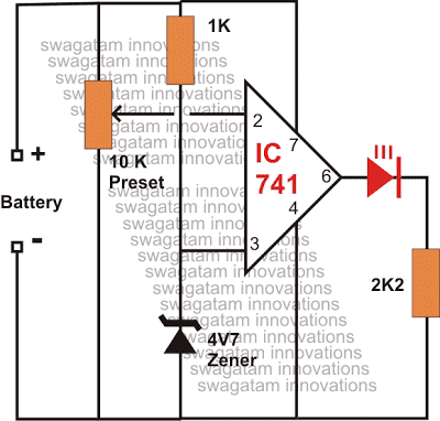
The proposed circuit was requested by one of the avid readers of my blog. It is a low battery warning indicator circuit using op amp IC 741 and can be used for monitoring a particular low battery voltage threshold.
Circuit Operation
The circuit may be understood with the following points:
The entire configuration is wired around the IC 741 and it becomes the heart of the circuit.
Basically it is configured as a comparator with one of its inputs clamped to a fixed reference level while the other input used as the sensing terminal.
Here as can be seen in the diagram, the non inverting input is provided with a fixed reference voltage through a resistor zener network.
This input is fixed to about 5 volts.
The other inverting input pin #2 is wired via a preset to sense the input supply voltage from the source.
The preset is adjusted such that the voltage level at this input becomes lower than the fixed reference voltage at the other pin of the IC as soon as the source voltage becomes lower than the desired threshold level.
When this happens the output of the IC immediately becomes high, illuminating the connected LED.
The illuminated LED immediately provides the indication of a low voltage situation so that the required actions may be initiated.
Optionally, the output may be replaced by a piezo buzzer instead of the LED for getting an audible response of the above situation, eliminating the headache of monitoring the LED condition every now and then.
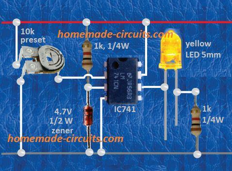
The above circuit can be modified by adding a relay stage for a latching facility, so that the relay latches and stops oscillations at the set low battery thresholds.
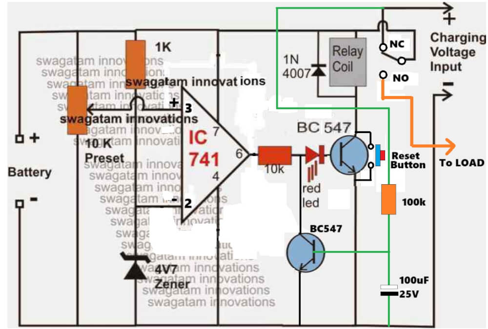
How to Setup this Low Battery Indicator Circuit
The above low battery indicator circuit can be even further improved in the following manner for controlling both lower and the upper charging thresholds:
Initially keep the 100K preset link disconnected.
Apply a 14.4V source from the "Battery" side and adjust the 10K preset such that the upper relay just activates, confirm the triggering by subsequently moving the preset to-and-fro.
Glue it once fixed.
The LED will respond by switching ON to the fixing of this preset.
Now reconnect the 100K preset feedback link, and reduce the input supply to about 11.2V. Make sure it has a high resistance initially.
Next, slowly adjust the 100K preset such that the relay just deactivates (at the 11.2V).
Confirm by flipping the preset as above. Ignore the lower relay as it will switch ON as soon as the input supply is switched ON, so its operation is obvious.
That's it, the low battery warning circuit is all set now and will accurately respond to the above settings or any different setting that may be preferred and implemented by the particular user.
IC 741 Low Battery Indicator Circuit with Relay Cut-off
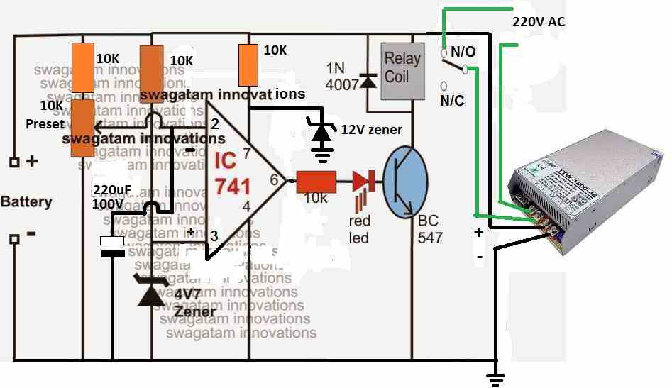
The following circuit shows how the above low battery indicator can be enhanced with relays for achieving an automatic low charge and full charge cut for the connected battery, and also a cut off for the load during a low battery situation.
The upper relay becomes responsible for cutting off the battery during over charge and low discharge level, while the lower relay cuts of the load as soon as the battery reaches the unsafe low discharge zone and as soon as the upper relay reverts to charging mode




Questions & Answers
connect LEDs at the outputs of A1 and A2 and ground with 1k separate resistors.
Now apply 170V and adjust P2 such that A2 LED just lights up.
Next apply 245V and adjust P1 such tha A1 LED just lights up.
Your circuit is set now, the relay connected at the collector of the transistor will also respond correspondingly.
Swagatam, sir,
I think I've cracked it, Instead of the 10k preset, I used a voltage divider: a 12k in series with a 27K. From between these two, I was able to obtain a voltage of 3.86V at Pin 2 – Pin 3 had 4.49 VDC – and, which triggered the transistor via Pin 6 and tripped the relay, and the lights, connected to the normally open contacts, cut out.
Now to assemble all three circuits.
Stephen Gard
OK Stephan, that's great, no issues, if you have solved it you can go ahead with it…..
(Reposted without links)
Swagatam,
Thank your for your well-conducted and informative site. I have learned much from it. I am trying to adapt your 741 Low Battery Cut-Off circuit for use with a 6VDC lighting set-up, and I am having some difficulty. I hope you can advise me. Here is what I wish to do.
1. I have four high-power white LED spotlights. They each require 3.2VDC @ 34mA.The four lights, wired in parallel, draw 82mA at 3.2 VDC. So that is the load.
2. The supply is a single 6.5VDC SLA battery. I attach a 33 Ohm 1 Watt resistor in series with the negative supply to the 4 x LEDS, as a current-limiter. I wish to use ONE battery only for the entire circuit, no separate supplies. It will be installed in a friend's garden and not get much maintanence! So it must be fully 'automatic'.
3. I have a solar-panel (5W 17 volt) that charges the battery and a darkness detector. Now I wish place your 741 Low Charge Cut-Off circuit (with relay) in between these two circuits, to prevent the 6.VDC SLA from discharging too far. The solar charger supplies only a small amount of current, and there will be no-sun days, of course.
If I understand the operation of your circuit, when the battery voltage drops, the 741, via Pin 6, allows current to flow through Q1 (the BC547), tripping the relay coil. My 4 x LED load is wired to the NORMALLY-CLOSED contacts of the relay (NEC EA2-4.5VDC), and when the coil is energised via Q2, they disengage the load by switching over to the NORMALLY-OPEN contact. So no current flows, and the 4 x LEDS go off.
That is what I wish to do, but I cannot make your circuit do this. The only change I made to your circuit was to the 10K pre-set pot. My pre-set over-heated. I measured the R, and replaced it with a 12k ohm 1 watt fixed resistor
b. This arrangement delivers 5.65V to pin 2 of the 741. Pin 3 is set at 4.52 V, from the junction between the 4.7V Zener and the 1K resistor connected to the +ve terminal of the battery.
c. To test, I connected one side of a diferent white LED load to the NC pins of the relay, and the other side to the battery ground. This load draws 2.8VDC, at 22mA.
d. I connect a tired old dry-cell battery to this circuit, and on my DMM, I watch the supply voltage drop.
4V99. 4V96. If I insert the DMM at Pin 2 and try to take a reading, the voltage goes down slowly.
e. So I connect a 2MegOhm pot in between the 12K and Pin 2, and bring the voltage down.
But now I notice that the voltage on Pin 3 is droppng as well. For example, from 4.351 to 4.348V.
It seems that the two pins will never achieve the diffential that will trip the relay.
When I connected the fixed resistor, I did not take it to ground, as the original circuit did, after the 10K preset. If I connect this fixed resistor to ground, Pin 2 goes low and the relay trips, but I don't think that is correct.
Can you please advise what I am doing wrong here?
Sorry for such a long letter!
Stephen Gard
Swagatam,
I am still testing to get exact values for my requirements. I am also drawing up the whole device in TinyCAD, and can send you a png of the completed three-part circuit, with test-points and voltages marked, if you wish.
Stephen Gard
Yes, why not Stephan, I'll be extremely happy to publish your efforts in my blog so that other can also benefit from it.
I appreciate your positive thoughts…kindly do send them.
And whenever you do something new in electronics, please make sure you share them here for us.
We all will love to see them.
Let me know if you need any further assistance?
Thanks very much.
Swagatam,
I added this circuit to my solar lighting set-up, but there is a problem. The relay must be activated to cut off the current to the LEDs. But this drains the battery even further. Finally, the battery is drained so much that it cannot activate the relay, which then returns to the NC condition, powering the LEDs, and draining the battery even further. After one dull day, when the solar panel could not recharge the battery, the lights do not work at all, because the battery was drained so low. Perhaps a timer would be better? I am running the whole set-up from just one 6VDC SLA battery, and don't want to add any other power sources. What do you suggest?
Stephen Gard
Stephen, the solution is to simply swap the pins of the IC, meaning connect the preset pin to pin#3 and the zener to pin#2.
In the above situation the load must be connected via the N/O contacts, so the LEDs stay illuminated as long as the relay is activated (voltage normal condition), as soon as the voltage drops below the lower threshold the relay and the LEDs all shut off without causing any further discharging issues.
Thank you, Swagatam, I carried out this mod, and now it all seems to working as I require, The set-up is currently undergoing a long-term (1 week or so) outdoor test, and after this, I will construct the final (weather sealed) installation and send you a schematic and some photos, as promised. I note that the circuits (there are three) still draw 12mA, even when the LED lights are off, but perhaps the solar-panel will keep ahead of this. The weather for the next week includes sunny and cloudy periods, so my solar-charged set-up should have a good test period,
Stephen Gard
That's great Stephen! I will certainly love to see the pics of the finished design, and also post it here for the viewers.
The quiescent consumption should not be more than 5mA according to me, i think something may be leaking through the output of the opamp, a 3V zener diode in series with the transistor could possibly fix this issue too.
Swagatam,
I got this all installed and working, but by that time, I had learned a lot more about solar lighting, and realised that my approach to this project was wrong: all I needed was a Joule Thief! However, the experience was very helpful, and your low-voltage cut-off circuit works fine. I plan to use it for a 6VDC solar-powered water pump… wilol report back when that's done.
Thanks for your help and advice,
Stephen Gard
That's great Stephen, I congratulate you on that. Best wishes to you.
hai swagatam!!! I had connected this as your circuit.. but when the circuit cut off the output..the battery voltage increases then the relay deactivates and the output works and it again activates and cut the output …this happens simultaneously ..how to cure it..
Hi Dharma,
Please connect a feed back resistor link from pin6 to pin3 as shown in the last diagram, this will prevent the circuit from oscillating at the threshold points.
HI
Can you please explain what is the purpose of using a bipolar transistor in the 3rd circuit?
why are we using it?
for driving the relay.
hey
can i used 3rd circuit diagram for 12 volt 7.2 to 45 AH battery? And in this circuit there is two battery supply for one is relay operate & another is for load?
you can use it…there's only one battery supply that connects with the load
Hello sir,
Plz I need clarification on ur last circuit dat has two relay. I built d circuit for my 12v inverter as charge control but d problem is i got d first conrol using 10k VR for 14.5v auto cuttoff but.for low batteery sensing I could not get what I want to deactivate at 10.5v. All I got was it deactivate at above 11v and even that I have to tuned d 100k VR toward zero ohm so what do i do to achieve low battary dectation at exactly 10.5v instead of above 11v
Hello Beelal,
try a lower value pot in place of 100k, may be a 33k pot and reduce the series 10k fixed resistor with 1k
Hello,
i see 2nd diagram 10 k preset connect @ 2 pin & in 3rd diagram 10K preset connect @ 3pin of IC. Another question is that I have UA 741C IC can i use it or there is difference IN UA 741 & LM741 please guide as i used it for 12 volt 7.2 AH battery.
Connect the pinouts as shown in the third diagram.
all types of 741 will work for this circuit
Hi Swagatam,
You have recommended this third version for my hi/low contacter.
You suggested that I don't require the second relay.
Which one do you mean and what was it's original function?
Thanks for this
Yours
Carl
Hi Carl,
The lower relay is not required for your application.
The circuit is a battery over charge/discharge controller.
Hi swagatam,
For the third circuit, I would like to know the exact values of the potentiometers, because i am only going to put resisters instead of potentiometers.my circuit will be using 12v input, 12v battery and the load current will be 3a.
Hi Anthony, the simplest way of implementing it is to first set the thresholds with pots and then measure the pot resistances to get the exact values of the fixed resistances.
The pot can be removed thereafter and replaced with the measured equivalent resistances.
can i use this circuit for 24v gel battery with 180 ah??
yes can be used..use a 324 IC for the opamp.
hai sir,
I made this circuit it is working perfect with sugar cube relay but it cant pull the coil of a 6 amp 200 ohm 12v relay,I am making a 800 watt relay,since the current has to pass through the relay I have to use a high amp rating relay,how to solve it.
Hi Vijeesh,
according to me a BC547 transistor should be able to pull a 200 ohm relay easily, try reducing the base resistor to 4k7 and check the response, or you can also try a 8050 or a 2N2222 in place of the BC547 for the same….
Swagatam Majumdar …sr….
My ups is 40W ..
Battery is fully charged is there ..
But my ups is showing battery low why sr…
sharanabsava, check the battery voltage while the inverter is operating and without any load….if the battery volatge drops then that would indicate an incorrectly charged battery or a faulty battery…also check the current with an ammeter in series with the batt positive….if it indicates high consumption without any load then the fault could be in the inverter, not the battery
hello
i used the above circuit to shutdown my inverter when battery voltage is 9.5v but inverter goes on and off severally at the set voltage.
that can never happen….use the second circuit, remove the 100k resistor and adjust the 10k preset such that the relay just cuts off at 9.5V and activates at around 9.7V….once this is done the circuit will implement the same accurately each time the battery voltage falls to this level.
Dear Sir
Thanks for your prompt reply to my other query and referring this circuit for my purpose. Kindly help me with the following queries regarding this circuit
1. To use a relay can the LED and its resistance (as in first diagram) be simply replaced by the relay OR is it mandatory to do the other changes of 2nd diagram like addition of transistor.
If I want to use <12v as the voltage to activate the relay will the required zener diode be of 12v OR as shown in diag 4v is needed.
3. What will be time required by the relay to act. (will the relay be immediately energized as soon as voltage falls below set 12v Or will some time be required and Vice Versa when the voltage again resumed to normal).
Thanks
Dear Ankit,
the IC will not be able to handle a relay directly, therefore a transistor stage will be required as shown in the second diagram.
The zener diodes should have a much lesser value than that of the supply voltage level, so for a 12V supply any value between 3v and 6V would be OK for the zener diodes.
the relay will act almost immediately as soon as the voltage crosses the set threshold limit.
….if the 100K feedback resistor is used then the restoration will not be immediate rather as per the 100K response…lower values will produce relatively quicker restoration….as the resistor value is increased the restoration point will move backwards (will be delayed proportionately)
Dear Sir
Kindly advise if 4.7V zener diode is not available then can 3.3v or 7.5v zener diode be used.
Dear Ankit, yes any zener below 8V will be fine…
Dear Sir, I made the circuit exactly according to second schematic and it is working fine. Just one query, In this Initially at normal voltage the relay is activated and when the voltage drops below the low level then the relay gets deactivated. CAN this function the OTHER way ie at normal voltage the relay remains deactivated but when voltage drops it activates.
Further what change may be required if low voltage cut is to be set at around 12V (currently it is 5V probably)
Thanks
Dear Ankit, what you are asking is not recommended because if you allow the opposite to happen that would mean at the lower critical level the relay coil will be energized and this would lead to even further consumption of the battery which will in turn discharge the battery even faster…….. this won't be a favorable situation for the circuit and the battery.
by the way you can do it by simply changing the NPN transistor with a PNP…and connect the relay diode stage across its collector and ground.
Thanks Sir. As per your suggestion of using PNP, will the ground be emitter or the base.
emitter will go to the positive….
Dear Sir, I did all the changes with pnp BC 557. But now the circuit is not working. Kindly advise
Dear Ankit, you might have done something incorrect with the connections for sure…otherwise there's no reason why it wouldn't respond….relay should be connected between collector and ground….emitter to positive supply….base to opamp resistor/LED……relay diode cathode must go to transistor collector…anode to ground
the LED polarity needs to be reversed.
Dear Sir, Thanks for the reply. After reversing the LED polarity, the modified circuit is working fine. As a final piece of advise regarding this circuit, kindly let me know the following-
1. What is the appox consumption of the circuit (on 12V battery) (when the relay is in deactivated stage), and
2. Is it OK to keep the circuit connected 24X7 or should it be switched on only intermittently (ie will continuous operation reduce the life of circuit)
Thanks
Dear Ankit,
increase the value of the perset to 100k, and same for the zener resistor, this will allow just a few mA current to be consumed by the circuit (only as long as the relay is not active)
the circuit can be kept powered ON infinitely without any harm
Dear Sir, The circuit is working as intended (using PNP so that relay is activated when voltage is low). However on borderline voltage, the relay chatters. Can something be done to avoid this eg adding delay with IC 555 or some other way. Thanks
Dear Ankit, just connect a 100uF/25V cap in parallel with the relay coil, this will take care of the issue
Dear Sir, I connected 100uF/25V cap in parallel with relay. Though this works fine when I test it at my work bench with a dc adapter, but as soon as I use the circuit in car (12V 70 Ah battery), the relay again starts chattering at borderline voltage.
I maintained the polarity of caps (+ to + of relay)
The slight modification that has been done to your original circuit (in addition to using PNP) is following
1. I am using 2 relays in parallel (as I need 2 switches and double pole relay not available) (diode put across both relays)
2. The 100uF 25 V caps have been connected to each of the relays separately
3. I have connected a buzzer in parallel to the LED (buzzer spec 3V to 30 V)
Kindly advise to prevent relay chattering
Thanks
Dear Ankit, do you have the feedback resistor in place? (between pin6 and pin3)
anyway, try increasing the value of the cap to 1000uF
or try placing the 100uF across the base and emitter of the BC557
Yes, the resistor between pin 6 and 3 is there.
Which option will be better increasing value of each cap to 1000 or placing cap between E and B
first try the E,B, option if it doesn't then you can try the 1000uF method
Great circuit , i wanna use it with Automatic Micro UPS , but what AMP does it support ? i need to use with 5 AMP Micro UPS
thanks, it will support any desired amp, 5 amp can be easily used with the shown circuits
Thank you ,
it's really good circuit , but i can not understand , in wanna use 2nd circuit with your great Auto Micro UPS circuit , but what is charging voltage input ?? is this circuit has built in charger ?!! i'm really confused !!
i wanna Auto Micro UPS to cut off the load when 12volt battery is going down and reaches its critical voltage
who to use this circuit with Auto Micro UPS ?
thanks in advanced
This diagram is correct:
https://drive.google.com/file/d/0B2VgP4YQwP4ETzczQ2Y3VExKX00/view?usp=sharing
you can use the second circuit from the above article and use it as indicated in your diagram.
Hi Swagatam,
I'm back again…. 🙂 …. I'm working on a digital thermometer using ICL7106 and an LCD display. The LCD has an icon of BAT for low battery indication. The main power supply is a 9V battery, reduced in 5V by a 7805 regulator. I need to have the icon BAT light on (which is terminal 40 of the LCD and was not included in the original project) whenever the battery goes below the minimum of the regulator, which is 4V. The LCD is common Anode. How can I interface this circuit with the digital thermometer and what changes do I have to do?
Best Regards.
Nélio
Hi Nelio,
you'll need to first confirm regarding what logic level pin40 is assigned for (zero or high?) After that you can use an opamp based low voltage detector circuit for activating this pin with the relevant logic level when the low voltage is detected….for converting it into a digital thermometer you'll need to use a temperature to volatge converter stage and integrate this with the voltage sensor input of the IC 7106
Hi Swagatam,
The part of the thermometer I have. All I need is to trigger the BAT icon in the LCD when the battery goes low. How to I know what is the logic level of pin 40 of the LCD?
Best Regards,
Nélio
Hi Nelio,
you can manually inject a 5V supply through a 100k resistor into this pin, and/or do the same by connecting the pin to ground via a 100k resistor….and check the response on the low batt icon…this will let you know the logic assignment for this pin.
Pls sir i have made the first circuit nd it's working fine…my question is(1)is the second diagram used for cutting the relay when voltage increases to 14.4v cos it does not seem like a low battery circuit since preset is connected to pin 3 and zener to pin 2 and i want to build this second circuit for battery full cutoff at 14.4v .(2)i want to add the first circuit to my sg3524 inverter without relay driver stage so i'm planning on connecting pin6 of the op-amp to pin10 of sg3524 so that it will shutdown my inverter at the low voltage level will it work like that?(3)what will be the effect of adding a 2.2uf 400v fan capacitor in series to the load at the output of my inverter?
victory, the second circuit has both the features, it will switch ON the relay when the battery reaches the full charge value…and will switch OFF the relay when the battery reaches the low charge level…the low charge cut-of setting is determined by the value of the feedback resistor connected across pin6 and pin3 of the IC.
yes it will work in tat way with SG3524 shut down pin….
capacitor should be added in parallel to the load, not in series…it will help to modify the square wave to a sine wave.
If the second diagram has both features then what is the extra feature of the 3rd diagram with the second relay
the 3rd diagram allows the load to access both the SMPS voltage as well as the battery voltage depending on the upper relay switching, and the battery condition.
Hello,
I have a 28v dc power supply and I am looking for a circuit to monitor voltage drop below 10v in the load. I want to have led light up when load voltage is above 10v and another led to light up if voltage drops below 10v. I also want the led to draw power from the power supply instead of the load. How can I achieve this please? Thank you.
you can use the circuit, and connect one LED from positive to pin6 and another LED from pin6 to ground….both these LED must have a 10K resistor in series.
Use LM321 IC instead of 741 since LM321 can work with upto 32V supplies
…and use 10k for the zener resistor
Can I use this circuit for 14V DC or 16V DC?
dear sir i real enjoy your circuit design and analysis. can this 12volt be modified to 24volt. if yes what are the component to add
what is the battery AH rating? and also specify whether you want it to be automatic or manual OFF
Do you have any schematic with an adjustable power supply with atleast 50amp output
you can try the design that's I have explained below:
/blog/2016/09/high-current-lm317-variable-power-supply-circuit.html
hello sir
can i use this circuit for lithium ion battery whose max charge is 3.8- 4.2V.
i am asking this question bcoz my device is single battery operated and if i use above ckt, as my battery is drained my reference voltage will also vary since their is no other source of power ,
suppose i use zener of 3.3V for getting regulated reference and battery voltage drops below 3.3v ,
in this condition will this circuit work or not
hello rupesh, the above circuits will not work with 3.3V supply, you can try the following design instead
https://www.homemade-circuits.com/2013/05/low-battery-indicator-circuit-using-two.html
Sir you are superb blowing
Sir i need help i have few question will u confrm
Is this above circuit will work on 100ah battery 2ndly i want to confrm i dont understand how much we will apply voltage and current needed?
I am talking about 3rd ckt .
Sir what should be connected at the load and where is the red and green led whixh shows that battery is charging and full
I want to id so that i take help
Thank you Aizaz,
you can use upto max 18V, and current can be upto any level that you prefer depending on the battery size. If your battery is 100AH in that case you can apply a 10 amp or 12 amp input….but make sure the relay contacts are rated to handle this much current….and if the relay is rated at some higher power then the transistor will also need to e upgraded, so better to go with a 2N2222 instead of the shown BC547
the load can be an inverter or lamp anything that you intend to operate when the battery is fully charged.
for connecting the LEDs you can refer to the following circuit
https://www.homemade-circuits.com/2012/07/make-6v-4ah-automatic-battery-charger.html
Thank u sir let me try this circuit i want also is this circuit is fully automatic i mean it will automatically stop charging when battery is full
yes it is fully automatic.
2ndly i want to confrm should i make any changes if i use 2n222 transistor?
click "load more" button below
And a 12 v relay are usually upto 25amp m i right sir?
No changes would be required for a 2N2222, a 12V relay may have a huge range, not limited to just 25Amp, it will depend on the user to select their preference.
however 25A will be enough for a 100 AH battery and 10A charging
Answer plz
sir i have made the above 3rd diagram circuit and i have used everything as u mentioned the question i want to ask should i give it direct 10amp and 18v or should i make a adjustable as u have mentioned that first apply 11.2 volt etc so from where i apply this as i have transformer of 10amp and 18v and lm317 only drawn 1.5amp current so how i do that i am new to electronics so plzzzz support me i will very thankfull to u
aizaz, for setting up the circuit as per the article, you will need an adjustable power supply circuit, if you don't have one you can build a temporary one by using an LM317 regulator IC.
while setting up the circuit the current input is not important, only the voltage must be set appropriately as mentioned.
please note that the 100K feed back preset was not calculated by me, rather chosen arbitrarily…so if you find the relay triping back at above 11V or 11.5V then you may have to use a higher rated preset, may be a 220K or 470K etc.
remember the current from the transformer while charging the battery must be 10 times lower than your battery AH rating.
sir i have made the given third circuit but i cant get voltage on ic when i check on pin 7 and 4 and i also didnt get the relay connection as i think i have mistakenly wire the relay conection so which is nc and no in the diagram plz explain brefly
Aizaz, Please check out the following article to learn exactly where the N/O and N/C pins are located in standard relays
https://www.homemade-circuits.com/2012/01/how-to-understand-and-use-relay-in.html
Sir i hav tried the following circuit but not working as it cant output the voltage and current i have tried my level best but unfortunatlly fail plz help i am so worried iTs my 20time i draw a circuit just hear the trip trip sound of relay but cant get output voltage whn i check by multimetr
you may be connecting the relay contacts incorrectly, please show me the image of the relay, you can show me an online image link of that relay I'll identify the pinout details of the relayfor you.
Sir i am using exactly this one but colour is black 🙂
elgammalelectronics.com/Products/Details/7eb6a416-fe94-4359-a51f-fcb128443ba7
this relay is already explained in the link which I provided you in the previous comment…I think you should first learn all the basics of electronics then start building circuits….
hello sir,
good morning ,
i need solution for battery voltage indicator ,
there are six 12volt 7.2Ah batteries in series adding equal to 72 volt dc
i want to monitor online battery voltage continuously while indication for low battery indication,
i have seen many circuit ,all are up to 24 volt .
in my case it is 72 volt dc so how to monitor such high volt.
do you have any similar circuit .
thanks
Nikhil.
hello nikhil,
you can make the following circuit, as many as required, and connect them all in parallel with your battery,.
https://www.homemade-circuits.com/2013/05/low-battery-indicator-circuit-using-two.html
after this you just have to set their presets at the respective low level thresholds, for getting the relevant battery level indications.
apply the preferred lower threshold mains AC value to the transformer based power supply which is used for powering the opamp circuit, then adjust the preset until the LED just illuminates
Hello sir Swagatam,
Please I want to use the above schematic (second one) for low battery auto-cut off. I already have an automatic charger circuit which you recommended to me. I want to connect the circuit in such a way that the relay contacts will act as a switch to 7812 voltage regulator which will in-turn power the driver section of an inverter. My questions are:
1. How do I set it to activate/deactivate the relay only when battery is low, say about 10.5V, such that when the activation/deactivation occurs, the relay stays in that position until the inverter is switched off.
2. If I want to use it for higher battery voltages such as 24V, 36V, 48V and higher, how do I connect the opamp since it has a maximum supply voltage.
3. Do I need to change the values of the zener and feedback resistor for higher voltages?
Anticipating your usual prompt response. Thank you sir.
Hello Godson,
The anseswers are as follows:
1) remove the 100K feedback resistor, it won’t be required. Through a separate SPDT switch connect the N/C of the relay with the base of the transistor, make sure to connect a series 10K resistor with this link. Initially keep this switch in the OFF position, feed the 10.5 or 10.7V to the circuit from the battery side and adjust that 10K preset such that the relay just clicks ON. In this position increase the input voltage to may be 12V or 14V, and switch ON the SPDT switch…now the circuit is all set, if the voltage drops below 10.5V the relay will switch OFF and latch up in that position until the SPDT switch is switched OFF and ON again, and if the voltage is found to be over 10.7V.
2) for higher voltage you can modify the supply pin#7 as shown in the following figure, and add series resistor with the preset.
https://www.homemade-circuits.com/2012/08/make-this-48v-automatic-battery-charger.html
3) No need of changing anything else for higher voltages, except the above.
sorry please ignore the first idea, it is incorrect and won’t work.
I’ll draw the design and update soon.
Ok sir. Thank you very much for the prompt response. Actually I wanted use the “Battery Voltage Status Monitor Circuit” for this purpose by attaching a relay to the last LED output. But on a second thought, I decided to use a separate low battery indicator circuit and that’s why I’m asking questions on this post. And also, i don’t want to tamper with the pin#10 of the driver IC, that’s why i want to work with relays. I’ll wait for the updated design. Thank you sir.
Godson, actually you can use the 2nd circuit exactly as given without changing anything, instead of supplying the charging voltage at the relay contacts you can configure it with your inverter driver circuit. as long as the voltage is above 10.5V, the relay will be in the activated mode powering the inverter driver stage, and the moment battery supply goes below 10.5V, the relay will switch OFF to the N/C point….
the 100K feedback resistor can be removed, it’s not relevant for this application
the N/O point of the relay will need to be wired with the inverter driver circuit, and not the N/C….
Hello sir Swagatam,
Thank you so much for all your replies. I’m responding to the last reply that you gave as regards the second circuit.
Here are what I understand, and I need you to confirm them:
1. I’ll use the circuit as it is and remove the 100K feedback resistor.
2. I’ll use the relay contacts (N/O and COM) as the switch for the inverter driver.
3. In order to set the circuit, I’ll apply the lower voltage, say 10.5V for 12V battery, at the battery points in the circuit, and then turn the preset till the relay just deactivates, and then I’ll turn the preset back and fort to confirm the relay deactivation.
4. In order to use it for higher voltages, I don’t need to change any of the components, all I need to is to connect pin#7of the IC according to how it is in the link you gave above.
Please confirm those four points sir. I also have some questions:
1. How do I connect the LED so that it will light up only when the relay deactivates, i.e when low battery is detected.
2. I want to use a 7812 voltage regulator to power the inverter driver (if I’m using 24V and above), do I need to connect a capacitor across the input and ground and/or output and ground of the regulator? If yes, kindly suggest the value(s) of capacitor(s) to use. Thank you sir.
Hello Godson, all your 4 points are correctly assumed, for above 24V application in addition to the pin#7 modification you must add a series resistor with the pin#3 preset, and increase the pin#2 resistor to 10K.
for LED indication you can simply connect an LED network having a series 1K resistor parallel to the relay coil.
for a 7812 IC you can connect a 10uF/50V at the input side and a 10uF/25V at the output, although this value is not critical.
preset series resistor can be a 10K for supplies over 24V
Ok sir. Thank you for the prompt reply. Its quite explanatory. But I want the LED to turn on only when the relay deactivates. If I connect it the way that you explained, it appears that it will remain turned on as long as the relay is activated.
sorry, in that case you may connect the LED parallel to the collector emitter of the transistor or across pin#6 of the IC and the positive line…in both the cases use a 1K or upto a 4K7 resistor in series wit the LED
hello good morning thanks for the great work you do.
the circuit performed perfectly and effectively in turning off when the battery is low i set mine to cutoff at 11.6v
Glad it worked, keep up the good work..
sir ,good day .which pin-out of the relay conected to BC547
the coil pinouts
thanks. Sir pls i need 12v battery charger circuit for lithium ion 18650 pack .
Kabiru, you can modify the following article for charging your 12V battery
https://www.homemade-circuits.com/make-6v-4ah-automatic-battery-charger/
thank .sir pls once again is there any circuit for transformerless ac to dc converter ,if yes pls send me the link
transformerless is not possible, a minimum ferrite transformer has to be employed.
yes sir that’s what i mean
what is the Ah rating of the battery?
sir ,it is 40Ah
you can try the 12V 5 amp SMPS circuit which is included in this website…please search it online, the first result will be the one I have referred from this website
sir do you have datasheets for these component:ic 7805, lm 317, lm 324?if yes pis help me with links
datasheets can be easily found online, if you have any specific questions please ask me here I’ll clarify!
hello sir, im doing a project to charge up a 12V battery using 18v solar panel. So when the battery voltage drop at 5v the solar will charge up the battery and stop when the battery is full automatically. So can this circuit be used by adjusting the 1k pot or need other circuit??…please help me sir…thank you
Hello Muhammad, it is possible but a 12V battery can be discharged only upto 10.5V , below this level it is strictly not recommended.
thanks for the reply sir, but is there any other way to detect the 5v battery condition?
for detection you can use the above transistor circuit, and set it for detecting 5V…
hi sir, i have some question regarding with 3rd circuit with relay
1. may i know the function of feedback loop of resistor 10K and 100K resistor at IC 741…why do we need to adjust it with 11.2 input being reduce as you mentioned.
2. based on the setup guide you explain, i’m confused where should 14.4V source should be applied at the circuit…
is it need to be supplied at battery input or 12V dc input
3. during the setup, should the battery and 12v dc input stay connected in the circuit when moving the preset to-and-fro
4. Lastly, can the 12dc input replace with charging input to recharge the battery.
thank you sir.
Hi Muhammad, here are the answers
1) it is to enforce a small latching on the IC so that as soon as full charge is reached, the output gets latched. We must adjust this feedback resistor such that the latching effect breaks at the desired lower threshold which may be 11V for a 12V battery.
2) 14.4V must be applied from the battery side, so that this setup supply input imitates the battery voltage
3) No battery would be required because the input itself would be from the battery side.
4) Once the setup procedure is complete, the left side input must be connected with a battery to be charged, and the relay side must connected with the charging input voltage.
Thank for the reply earlier sir, but i get something to ask
i try to run simulation in multisim but can’t get an result….during setup, when the dc souce applied at battery input is 14.4v and preset 10k ohm is adjust to turn on the op amp it activate the relay. But when the 14.4v is reduce to 11.2v as you mentionesd, the op amp automatically turn off because voltage is reduce causes voltage drop at 10k preset drop, hence this also deactivate relay… so at when i need to adjust the 100k preset, because the relay already turn off when voltage is reduce to 11.2v
Hi Muhammad, I don’t recommend simulators for judging a circuit because simulator can be misleading if not optimized correctly, it is better to build and test it practically.
for the moment you can try removing the feedback completely and try again, and then try different fixed resistors for the feedback to test the difference in the low level triggering and which value gives the most appropriate results…you can also try other ICs LM321 and LM358 etc
Hello and thank you for this nice circuit and your support.
I have build the 3rd circuit and i have a question about setting up process in order to make it work right.
What do you mean with “Initially keep the 100K preset link disconnected.” ?
Do i have to keep disconnected the 10K resistor +100K pot branch between pin 3 and pin 6 ? or should i keep disconnected the middle pin od 100K pot?
Thank youin advance
Best regards
Ilias
Hi Ilias, Glad you liked this circuit.
You can disconnect the 100k/10K loop from any place, the requirement is to break the loop between pin#6 and pin#3 of the IC.
Hi, plz make a circuit for me.For telecom sector power source voltage dc48v 12000A where 47v low cut-off circuit with relay operated .plz reply me….I’m waiting…
Hi, what is the battery Ah rating?
The telecom battery bank Ah rating is 600Ah + 600Ah=1200Ah.
You can try the last circuit from this article:
https://www.homemade-circuits.com/low-battery-indicator-circuit-using-two/
Hi,
i simulated this circuit with computer. i can not adj voltage. what i do;
1.i shorted 100k pot. feedback only 10k.
2.I applied 14 v by battery and adj pin 3 10k pot. until led high.
3.reconnect 100k pot and applied 11v by battery.
4.adj 100k pot but led always low.
Did I make it wrong? Thanks…
Hi, sorry I cannot troubleshoot a simulation result, because practically the circuit is pretty straightforward and starts working immediately as per the specifications.
Ok. Is it true that I did it? can you confirm the steps?
1. feedback only 10k or open circuit ?
2.
3
4.
Thanks again.
1) Keep open circuit for the feedabck resistor initially
rest are all OK
Please, can the inverting and non inverting voltage can be equal. Just enquiry
The reference level must be always different than the cut-off threshold. They should not be equal.
https://www.homemade-circuits.com/2012/03/how-to-use-ic-741-as-comparator.html
sir pls clear this few question. 1.the place mark 12v DC input pls explain. 2.the place mark load can inverter output be connected there. 3. is this 3rd circuit charger on it own .wait for ur respond.
A battery will need a charging input, so naturally the 12V input is the charging supply input from a mains adapter.
For an inverter it will be act as a load since it draws current from the battery. so it can be connected with the bottom relay.
I woundn’t be needing it since it require 12v adapater because I don’t have any. but thanks for your effort so far.
The supply source can be from anywhere which can charge the battery. Without the 12V input the battery cannot charge.
Please how can I add SCR to the low battery 741 circuit above for shutdown pin of inverter circuit at 10.5V
You can try this:

Thanks sir, please which one is anode from the diagram
Adeyemi, you can refer to the following article for the details:
https://www.homemade-circuits.com/triac-circuits-working-and-application/
Hi Swagatam,
Could I use the last circuit (with two relays) above in the following manner:
I have a robot mower with a nominal 20v Li-ion battery. When the battery needs recharging the mower automatically returns to it’s charging station garage, and I want to detect that low voltage point and send an RF signal to open the garage door. Then when it is fully recharged I want to send another signal to open the door again to let it out.
The low voltage is 17.3v and the fully charged voltage is 19.7v so I would want to detect 17.3v and 19.5v. (I plan to use the two relays to independently trigger two RF channels from the 4 available on your RF circuits which are working perfectly).
Would the circuit work for this as it is shown, or would I need to change any of the components, please?
Hi Philip, the output from the second relay is always connected to a DC source, either from battey or from charger, so it cannot be used to trigger an RF. You will have to remove the second relay and use the N/O contact of the upper relay to activate a 4017 based flip flop, the output of the fli flop could be used for activating an Rf via a relay.
OK, Thanks for that. Not really what I want to do so I’ll have to look for another way of doing things.
Thanks anyway.
can Someone Help me simulating the first circuit in Proteus….I am facing some issues …Led is glowing for higher voltages rather than lower voltages ….what could be the reason??
Gud evening sir
Please sir can this ic be replaced with LM339 IC?
Yes it can be replaced but the output configuration will change…
I was thinking of making a 3.7v lipo battery discharge cutoff circuit when the voltage drops to approx 3.2v, can you suggest some links or ideas around the same using 741 or any other IC
Thank you,
Neeraj
You can try the following concept, and change the zener value and the transistor values according to your specifications.
https://www.homemade-circuits.com/battery-deep-discharge-protection-circuit/
Hello sir the last circuit u referred me to in this article I have built but the 100k preset is not responding to any feedback by deactivating the relay. The 10k preset do.???? what is it?
Hello Morris, the 100K preset decides at what lower voltage threshold the battery must be reverted to charging. It has a systematic setting up procedure
In the procedure on how to set up says when I adjust 100k preset the relay deactivates. I tried And failed to deactivate but the 10k do . After all that whn I reduce power source to 11.2 then to 14.4 the relay activates and deactivates. Is that all despite the 100k fails to deactivate as stated in the procedure above? Advise if it’s just ok that way. Thanks
There was a slight mistake in the drawing, the feedback link is supposed to be connected with the pin#3 of the IC in the second diagram. Please try again now.
Hi swagatam.
1)Can i use the first circuit (the one without a relay, with just the LED) with a 12v battery source?
2) if yes, can i replace the LED with a buzzer because i want to build this circuit so that the buzzer would sound at exactly 12.0vdc
3) In other to achieve the above requests, do i need to change any of the components (e.g the zener diode)
Thanks.
Hi Chris,
1) yes you can use the first circuit with a 12V supply
2) Yes you can replace the LED/resistor with a piezo buzzer unit.
3) You can do the above without changing anything in the design
Thanks for the quick response Swags.
If i build this indicator circuit for a 12.0vdc battery (for my inverter) and the piezo buzzer is activated(as in a low battery condition) how about if i connect the battery to a charger(my solar panel) and the battery voltage rises above 12.0v would the buzzer be deactivated automatically?
Hi Chris, yes as soon as the battery voltage increases above set low level threshold, the buzzer will stop buzzing, and vice versa.
Sir I think the the n/o contact of the relay so that when the battery reaches the full voltage level and the op-amp becomes high at its output and triggers the transistor to switch on the relay (turns to the n/c contact) and with this the battery is unable to charge further. Sir this is just a suggestion
Melvis, which circuit are you referring to?
Sir, if I need to use the first lm741 circuit for batteries of 4v or 6v, do I need to change the zener value or any other component values? If possible, how can I set up the cutoff using the preset for a 4v and 6v bat?
Binoj,
for 4 to 6V battery you can replace the 4.7V zener diode with a 3V zener diode or you can use 3nos of 1N4148 diodes in series. Cathodes will go towards the ground line
Hi Swagatam,
We exchanged some comments on one of your other pages (IC 741 Car Alternator Voltage Current Regulator Charger Circuit) and you suggested I take a look at the first circuit in this article. If you remember I was looking for a circuit to add an ignition warning light to an old motorcycle.
I picked up a few 741’s from a local webshop and have been playing around with the circuit on a breadboard. With the LED in the circuit it works as described. I have been testing with an old lab power supply to alter the voltage supplied to the circuit. Trouble was I need to modify it to get a 12v signal from the output (pin #6). The “dashboard” of the bike has fittings for the small BA9 lamps and I have installed LED replacements, but of course they are modified internally to work on 12v.
I read up here and other sites on the working of the 741 and it seems like to get 12v out I needed to put a 12v reference voltage in (pin #3). So I looked into the working of the resistor zener network and changed the 4V7 zener for a 12V example. The 1K resistor seemed to work OK and I get a reading of 11.9V at pin #3 which lights the 12V LED OK. Now this needs to go out when I turn up the voltage to around 13- 13.5V, but adjusting the 10K pot feeding the inverted input (pin #2) never raises the wiper voltage to be above the reference when the lamp should go out. I tried a couple of other pot values without success and the only change that seems to work is removing the 10K pot and feeding the changing input voltage (as would be put out by the bike’s generator) direct to pin #2.
So my question is – does this seem like a suitable modification to create a stable project? Or would you modify it differently? Looking forward to your thoughts, thanks.
Hi Martyn,
The 12V zener at pin#3 of the IC is not necessary. You can use any zener diode below 9 V and still setup the circuit to cut off at the desired threshold. The 10K preset adjusts the pin#3 threshold in accordance with the zener reference, so any zener below 9 V should work.
However if you are able to get a zener diode whose value is exactly equivalent to your desired cut-off threshold, then you can replace the 4.7V zener with this zener diode. In that case you can also eliminate the preset and connect the pin#2 of the IC directly with the source DC.
As far as the working of the preset/pot is concerned, it will definitely allow the voltage at its wiper arm to be adjusted right from zero to the maximum supply voltage level. If it is not doing this then either your preset is faulty or you may have connected it wrongly.
OK – so I looked at again and you could be right about the 10k pot. It was from a cheapo assortment from China. I found a better enclosed version which seems more reliable and that performed better with the 12v LED lamp. Couldn’t find the time to etch a board for it so just soldered it all to a small project board and it seems to work as hoped with the old lab supply. Just need to get the bike running and adjust it to function correctly with the alternator supply. Many thanks.
Sounds good! Hope it works correctly in your bike. Wish you all the best!
how to prevent the charging circuit from very high current drawn from 12V car lead acid battery when they are as low as below 8V. My own circuit have often burnt by bridge rectifier and transformer.
You can take the help of a current limiter circuit as explained in the following article:
https://www.homemade-circuits.com/universal-high-watt-led-current-limiter/
Hello sir, I have tried the circuit today but the second relay that is connected to the load is not bringing output
Hello Micheal,
Please tell me your exact requirement, I will try to suggest the right circuit for you.
Sir, my requirement is how to make low voltage indicator and cut off circuit for inverter
OK, then you must try the second circuit from the above article. Just make sure to swap the pin#2 and pin#3 with each other, and replace the “charging input” with your inverter +/- supply inputs.
Also please remove 100K preset feedback link, we can modify it afterwards when the circuit is confirmed by you.
I am after a simple cct to operate a relay to showw high dc voltage of 40v and must run between 24v to 45v.
Can you help please.
Please elaborate, I could not understand the exact functionality you require.
I have a battery charge that needs a simple cct that turns off the charger when the voltage gets to 41.0v. It need s operate a relay that can switch 240v ac 2a max
You can try the following concept:
Hello swagatam sir, I need to design a power supply failure indicator using IC741 op Amp,can you help me to design this mini project.I tried a lot but still there is no out come . Please accept my plea
Hello Sujal,
Can you provide more information about the project. Bceause power supply failure can be detected simply by putting an LED. If the LED shuts off that would mean there’s no power supply. How do you want to use the IC 741 and where exactly?
Sir, basically by using ic741 ,led,resistors capacitors and diode I need to make a small power supply failure indicator. The working should be in such a way that that the LED should glow when there is fluctuations in power supply or when the power supply is cut.
OK Sujal, let me see, I will try to figure it out and let you know soon….
Thank you sir
Sujal, there’s one question, if there’s no power supply, how will the op amp and the LED indicator work?
Sir even I am unaware of the answer for your question, but I found out an article for this problem with circuit diagram. can I know your mail so that I can send it to you.thank you
You can send the image to contact@homemade-circuits.com
Hi Sujal,
I saw your diagram in the email. The circuit uses a battery, so if you use a battery in your circuit then it is possible to build it. The battery can be a 9V battery.
Sir I have sent you another mail please do check it.
Sujal, I have uploaded the diagram in the below link. There are a few things I cannot understand myself. Where is the source of the external power supply? Which is the reset switch SW1, or SW2. I guess it is SW2. And, is your circuit working?
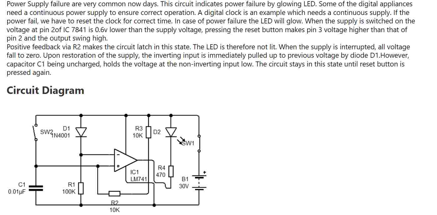
Yes sir I assumed reset switch as SW2 and I gave 9v battery as the power source, when I give power to the ckt the light blinks and when I take off the power supply it blinks. I am unable to understand what’s happening inside the circuit.i will refer to the circuit given by you
I can provide you the op amp circuit which will illuminate an LED when the external power supply fails or becomes low. But my circuit will require a battery also, a 9V battery….
yes sir please provide me with the circuit you are discussing about,I have a 9v battery .It would be a great help to my project
Sujal, You can try the following circuit:
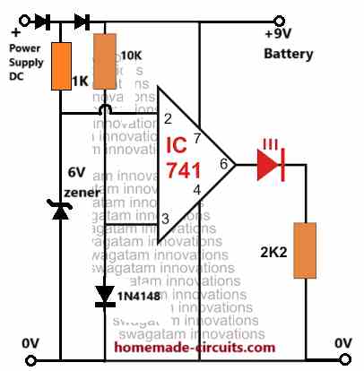
All diodes are 1N4148….
Sir thanks alot. Just one last doubt,what value of power supply should I provide to the ckt. also can you provide me with the working of this circuit if possible
Hi Sujal, the power supply DC should not be above 15V otherwise the IC 741 will burn.
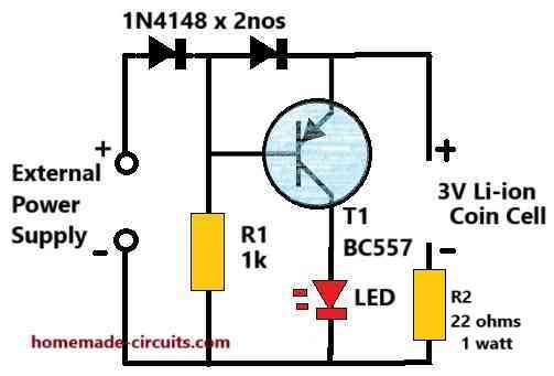
It is a comparator circuit, with its non-inverting input (+) clamped to a 1N4148 to create a 0.6V reference. The inverting input (-) is connected between two diodes to ensure that it is able to detect only the external power supply DC and not the battery DC.
As long as this external power supply on pin#2 of the IC is higher than the pin#3 potential of 0.6V the output of the op amp remains 0V and the LED remains shut off.
In an event when the external power DC on pin#2 goes lower than the pin#3 0.6V, the op amp output swings to +9V battery level and thus illuminates the LED.
Thankyou soo much sir. ❤
You are welcome Sujal!
Sujal, please add a 1N4148 diode from the battery +9V side also, otherwise the external power supply +DC will try to enter the battery and damage it.
Ok sir , sir one more doubt, can I use 1N4001 diode instead of 1N4148 as they are equivalent….
Yes, you can use 1N4001 diode for all the diodes shown in the diagram.
sir i made the circuit and it is working perfectly. Once again i thank you whole heartedly for your help and will stay connected with you for your help in my future projects <3.
Thank you Sujal, Glad it worked for you. Please feel free to comment if you have any further doubts
What zener diode should I use if my battery is a 3.7v 300 – 3500mah Li-ion battery (includes Li-po batteries too)
You can use a 3V zener diode, or, 3 or 4 1N4148 diodes in series, connected between pin#3 and ground….cathode towards ground.
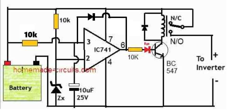
Hello sir. My question is, my relay flickers when the battery voltage reaches 10.5v which is the cut of point. I used lm358 OpAmp. Is it okay
Hillary, please try adding a diode between pin#3 and pin#6 of the opamp, as shown in the following diagram, and let me know if solves the problem or not.