In this post I have explained 5 useful power supply failure indicator circuits which can be used to get an instant indication regarding an input power failure situation.
This post includes the following 5 types power failure indicator circuits:
- Using transistor, LED indicator without battery, for DC power supply.
- Using transistor, LED indicator and with battery, for DC power supply.
- Using transistor, buzzer alarm, for DC power supply.
- Using transistor, buzzer alarm, for AC 220 V power supply.
- Using op amp, LED indicator, for DC power supply.
Main Function
The main function of the proposed power failure indicator circuits is to alert or notify about a power failure situation in an electrical system.
The circuit can be used for indicating DC power supply failures or mains AC 220 v power failures, depending on the application needs.
The indication is provided through an LED, or a buzzer or both.
The circuit may use a battery backup for indicating to keep the LED illuminated for a much longer duration of time.
If a battery backup is not is used then a high value capacitor could be used for keeping the LED or the buzzer activated for brief period of time.
A battery backup allows the LED indicator to remain illuminated for much longer periods of time, until the input power is restored. This allows the user to view the indication and get notified anytime during a power failure.
Now, let's proceed with the circuit diagram explanations.
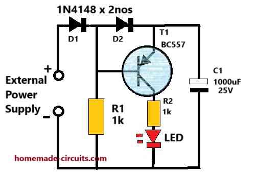
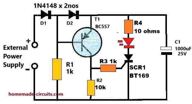
1) Using Transistor, LED, and without battery
Parts List
- Resistor 1k 1/4 watt 5% = 2
- Capacitor 1000uF/25V = 1
- Diode 1N4148 = 2
- LED RED 20mA 5mm = 1
- Transistor BC557 = 1
The above diagram shows how a simplest DC power failure indicator circuit can be built using a single transistor and a few passive electronic parts.
Circuit Description
As long as the DC input supply is ON, the transistor is reverse biased through D1 diode.
In this situation, the transistor remains switched off causing the LED to be shut off.
In the meantime, the 1000uF capacitor stores the specified amount of charge in it through the external DC supply source.
Now, when the external DC power supply fails or is cut off, the transistor base gets forward biased and becomes switched ON. Due to this the LED also switches ON using the stored power in the 1000uF capacitor.
The LED remains illuminated until the charge inside the capacitor C1 is fully depleted.
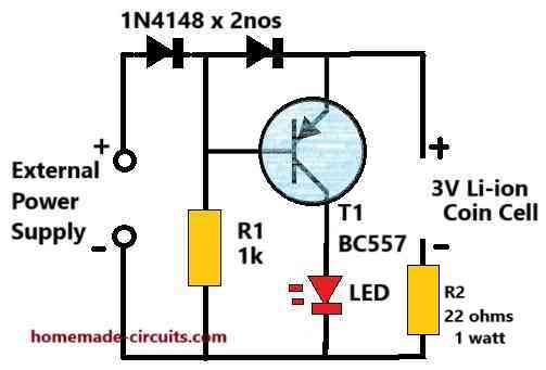
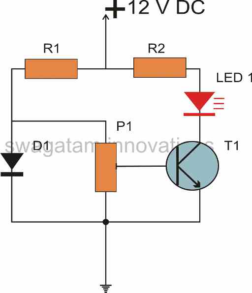
2) Using Transistor, LED, and with battery
Parts List
- 1k 1/4 watt 5% = 1
- 22 ohms 1 watt 5% = 1
- Diode 1N4148 = 2
- Transistor BC557 = 1
- RED LED 20mA, 5mm = 1
- Battery 3V Coil Cell Li-ion = 1
Referring to the above circuit diagram, it works like a DC power supply failure indicator using a single transistor, LED and a battery backup.
The battery is a small li-ion 3 V cell.
The transistor can be any small signal PNP transistor such as a BC557.
The LED can be a 20 mA, 3V LED, preferably red in color.
Circuit Description
As long as the input DC power supply is available, the PNP transistor base remains reversed biased through the D1 diode.
Due to this the transistor T1 is unable to conduct and keeps the LED turned OFF.
As soon as the input DC power supply fails or cuts off, T1 base becomes forward biased through R1 and it instantly switches.
The battery supply is now able to pass through the LED and illuminate it.
The illuminated LED indicates the power failure situation.
Diode D2 ensures the 3V supply supply is prevented from reaching the base of the transistor.
The maximum input voltage must not exceed 12 VDC, otherwise the 3V cell might get damaged.
The 22 ohms resistor allows the li-ion cell to trickle charge as long as the input power supply is available.
If possible please add a 5V zener diode right across the 3V cell.
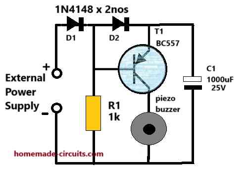
3) Using Transistor and Buzzer
Parts List
- 1k 1/4 watt 5% = 1
- Diode 1N4148 = 2
- Transistor BC557 = 1
- Electrolytic Capacitor 1000uF/25V = 1
- Piezo Buzzer 3V = 1
In the above design we find that an automatic power failure indication is provided by a single transistor and a small piezo buzzer.
Circuit Description
The above power failure indicator circuit design is quite identical to the 1st design using LED and capacitor. Here, instead of the LED we use a piezo buzzer.
While the input DC is available, the transistor is reversed biased and switched OFF.
During this time the capacitor stores the DC power inside it.
The moment input power fails, the transistor becomes forward biased and turns ON the buzzer using the stored energy inside the capacitor.
The buzzer sounds for a brief moment of time until the capacitor power is fully used up.
An audible alert sound is more effective than an LED indication, since the audible sound quickly warns the user, even while the user is inattentive and busy some other work.
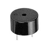
The piezo buzzer can be any small 3 V buzzer as shown in the following image.
4) Using Transistor, Buzzer, for AC 220 V Supply

Parts List
- 1M 1/4 watt 5% = 1
- 1k 1/4 watt 5% = 1
- Electrolytic capacitor 10uF/25V = 1
- Electrolytic capacitor 1000uF/25V = 1
- PPC Capacitor 0.33uF/400V = 1
- Diode 1N4148 = 2
- Zener Diode = 12V/1watt = 1
- Piezo buzzer 3V = 1
WARNING: The above circuit is not isolated from mains AC and is therefore extremely dangerous to touch in open and uncovered position. Maintaining extreme caution is strictly advised.
If you require a power failure indicator which will indicate the AC mains power failure, then you can use the above shown circuit.
It includes a transformerless power supply circuit for stepping down the AC mains voltage to a suitable DC for the circuit. A buzzer and a 1000uF capacitor are used for the audible indication.
Circuit Description
Referring to the above circuit diagram, 0.22uF/400V capacitor along with its associated parts forms the mains AC 220 V step-down transformerless power supply circuit.
This stepped down DC from mains AC is applied to the base of the PNP transistor which keeps the transistor reverse biased.
As long as the mains power is available, the transistor remains switched off, keeping the buzzer silent.
In an event when the AC mains power fails, the PNP transistor quickly becomes forward biased and conductive causing the buzzer to switch ON. The buzzer now sounds using the stored energy inside the capacitor C1. The buzzer remains operative and buzzing so long until the capacitor C1 energy is fully depleted.
C2 and Z1 ensures a stabilized DC on the base of T1.
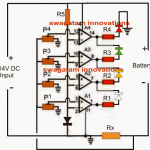
5) Using op amp, LED, and Battery

Parts List
- Resistor 1/4 watt 5% 1k = 1
- Resistor 1/4 watt 5% 10k = 1
- Resistor 1/4 watt 5% 2.2k = 1
- Diode 1N4148 = 1
- Zener diode 6V 1 watt = 1
- RED LED 20mA 5mm = 1
- IC 741 = 1
- Battery 9V PP3 = 1
NOTE: Please add a 1N4148 diode from the battery (+) side also otherwise the DC voltage from the power supply might damage the battery.
If you are looking for a power failure circuit using an op amp, then you can use the above shown configuration using an op amp.
Although the circuit is very accurate with its results, it appears to be an overkill compared the other transistor based designs.
Circuit Description
The circuit employs an IC 741 comparator, with its positive input (+) connected to a 1N4148 diode to establish a 0.6V reference voltage. The negative input (-) is coupled between two diodes, ensuring that it can only detect the external power supply DC and not the battery DC.
When the external power supply voltage on pin #2 of the IC exceeds the 0.6V potential at pin #3, the op-amp output remains at 0V, keeping the LED off.
If the external power DC on pin #2 drops below the 0.6V at pin #3, the op-amp output switches to the +9V battery level, illuminating the LED.
This concludes our article on simple power failure indicator circuits, if you have related questions, please feel free to post them through comment below.


Questions & Answers
Hi,
Thanks for this. I have the circuit with 3V coin cell assembled and it works fine. However, the coin cell is going flat after a couple of days, making it far less useful.
Do you have any idea why this might be?
Thanks again,
Dave
Hi, thanks for your updating the results, in that case please try increasing the R2 value to 1k and check the response, but for this the LED will need to be a really high bright type. Even in this situation, the cell might not last more than a couple of hours. So to solve this issue you can consider using a 3.7V li-ion cell instead.
Mr. Swagatam, I am trying to troubleshoot the headlights on my truck. The lights operate normal for about 15 minutes then blink off and on a few times then operate normally for a while then start blinking off again. The problem is I can only test the lights at night, which can be dangerous. I would like to build a warning circuit that sounds a buzzer when power to the lights is interrupted, so I can test during daylight hours. I would wire it in at the headlight and again prior to the control relay for the lights. Any assistance is greatly appreciated.
Thanks in advance
Jeff Marshall
Hi Jeff,
Any circuit detecting this situation will need to detect the power coming across the headlights. But if the power is switched ON to the headlights then the headlights will also get switched ON during daytime, which may be undesirable.
Let me know if this will work for you or not…then I can suggest.
Originally I was thinking of having a light attached to the + side of the headlights turning off when power was lost, however, an alarm works better. I would be driving with the headlights on during the day while driving since the lights only have the problem while driving. It does not act like a short (wiring problem) more like a relay or switch issue. I do not think it is a loss of the ground due to the lights are grounded next to the lights and is verified as good.
Thank you for your assistance.
Sure, in that case you can simply add a readymade buzzer across the + of the headlight and ground for the required detections. The buzzer can be any sound emitting device rated to work with your vehicles battery voltage.
Let me know if you have any doubts regarding the subject.
hi swagatam,
i did use a 1k resistor to the gate of the scr, but i must have made another mistake.
Anyway the circuit is now working !! as you suggested.
in DARK voltage through SCR is 0.066volts, zero milliamps,
in LIGHT WITH LED ON voltage is 7.81v and 1.77mA (using 9v supply).
Not that it matters but the SCR does not latch ???, covering the LDR up (dark) the voltage across the SCR immediately drops to 0.066v.
The voltage was measured from the +ve of the 9v battery and the Anode of the SCR. Is this correct? Anyway it seems to work with the SCR turning on in the Light.
dave
Thanks Dave, glad the circuit is now working for you.
If you are using a continuous DC across the anode/cathode of the SCR, then it must get latched upon applying a gate trigger, if this is not happening then either your SCR might be having some problems, or the DC supply across the SCR might not be consistent…
hi,
swagatam, i did what you suggested.
the circuit as is (no scr) works fine LED ON IN LIGHT OFF IN DARK.
Disconnecting the emitter of the bc547 from ground and connecting to gate of scr through 1k resistor, and placing a 10k resistor between gate and cathode (ground) generated the MAGIC SMOKE FROM THE SCR (i did connect a multimeter to the anode and cathode of the scr just to monitor the voltage when turned on). This was all done on a breadboard.
i am sure it was connected correctly. Perhaps if you drew your own circuit ?
dave
dave
Hi Dave, did you connect a 1k resistor in series between the emitter of the BC547 and the SCR gate, as suggested in my earlier comment?
If you did not connect the gate series resistor then you are bound to get the magic smoke from the SCR.
Now, you may have to replace both the transistor as well as the SCR, and repeat setup again with a series gate resistor…
Let me know how it goes…
HI,
Thank you you swagatam , i will try what you suggested and let you know if it worked
dave
HI,
actually i think i meant a Light sensor circuit.
i basically want to use an ldr to turn an LED ON IN LIGHT and and GO OFF IN DARK, to trigger an scr to control another circuit to turn it on, like a buzzer.
Hope that is explained better. (9vsupply)
thank you
dave
OK, to switch ON the SCR and the LED in response to light, you can disconnect the emitter of the BC547 from the ground line and connect it to the gate of the SCR through a 1k series resistor. Also, connect a 10k across SCR gate and ground.
As soon as the SCR turns ON it will get latched and permanently ON….
hi swagatam, could you help with the Dark Sensor schematic on this link
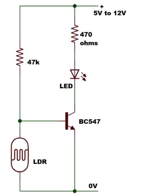
the circuit works fine as it stands, LED OFF IN DARK, ON IN LIGHT. I used a 50k pot instead of the fixed 47k resistor to adjust sensitivity.
I have tried using an SCR to link to another circuit to turn that circuit on.
i tried connecting the Collector of the bc547 (pin 3) to the gate of the SCR through a 1k resistor (to turn the SCR on )but it also turns the LED on even in dark. A10k also turns the LED on.
any chance of a simple circuit diagram to help matters
i have the bug for simple circuits, which i am trying to understand, and then i find out i dont.:(
Hi Dave,
With a DC supply an SCR will get latched and switched ON permanently once it receives a gate supply.
So in your case, during daytime while the BC547 is turned off, the SCR turns ON, and gets latched permanently, so now when darkness sets in even while the BC547 conducts and grounds the SCR gate supply, the SCR still continues to conduct because it is already latched ON.
Please let me know what exactly are you trying to achieve i will try to figure it out for you…
hey , swagatam,
your modified circuit with the scr in works just fine (i used a 2n5064) ! i’m really pleased !
many thanks for your time and knowledge you are a top man !
dave
That’s great Dave, glad the circuit worked for you.
Let me know if you any further doubts or questions…
hi, swagatam,
your circuit number 1 does work with a slow drain of the capacity gradually reducing brightness of LED as it drains the cap.
is there any way to dump the full charge of the cap all at once ? there seems to be some internal resistance of the bc557 which is giving a slow drain of the cap.
ideally i would like to dump the full charge.
thanks
Hi, Dave,
The slow drain of the capacitor is mainly happening due to the 1k series resistor connected with the LED, and this also depends on the value of the BC557 base resistor. If we remove the LED series resistor, the LED might burn due to the sudden high current from the capacitor. To ensure the LED does not burn we might have to introduce a regulator circuit which charges the capacitor only up to maybe 4V, and then we can get rid of the series 1k resistor.
However, even without the series resistor, you might still see some fading on the LED because the when the capacitor tries to dump the whole charge across the LED, the LED initially draws high current and illuminates brightly but consequently as the capacitor voltage drops, the LED consumes proportionately lower amount of current and starts diminishing with a fading effect.
Hi, re circuit no.1,
so i am now trying to use the emitter of the BC557 to trigger another circuit (which is separately powered ) on the gate of an scr 2n5064, but this does not seem to be working. Neither does it seem to trigger on the gate of a 2n7000 mosfet. how would i get this to work ? any chance of a circuit diagram.?
basically the led lights and fades as discussed as drawn in no.1.
i am now trying trigger an scr or mosfet with the same voltage that lights the led, to turn on another circuit.
thank you for your previous answer and time
dave
i hope this is clear.
This is how you need to connect the SCR with the BC557:
Let me know whether it works for you or not.
However, if you are using a different power supply for the LED, the SCR may not be required. You can break the emitter terminal of the BC557 and connect it with the (+) of the other DC supply, and connect the grounds in common.
hi, swagatam,
is it possible for you to draw the schematic of a simple total remove battery alarm and the charge in a capacitor or another battery is then used to light an led or buzzer. not sure if circuits (1) and (2) would do this ?
HI,
i guess circuits (1) and (2) should do the job.
basically if the battery fails or is removed accidentally, a buzzer or an led is illuminated.
thanks
Ok, sounds good!
Let me know if you face any issues with the implementation of the circuits…
Hi Dave, can you please elaborate on how the “simple total remove battery alarm” works? I will try to figure out…
Dear Sir You have suggested me this circuit I made this circuit but very unforthunately didnt work . Please find the circuit it this link
https://drive.google.com/file/d/1eRkD7T4ooUfvU0kyow4auZLqB3Xc7BgK/view?usp=sharing
Jobayer, try testing the circuit with a 12V DC power supply first.
Disconnect the circuit from 220V mains, and connect a 12VDC across the 100uF capacitor, make sure the polarity is correct.
When you switch ON power the buzzer must turn ON for a fraction of a second and then turn OFF.
After this switch OFF 12V supply and wait for a few seconds and again switch ON the 12V DC to the circuit, the buzzer must et again turn ON momentarily and turn OFF.
Please try this and let me know….
Is there a way to get the buzzer alarm to sound in an intermittent (slow beeping) sort of way rather than a continuous tone?
I think small intermittent piezo buzzers are available ready-made online, you can try one of those and see how it works.
You can also make one but that can be bigger in size and consume more power.
I just ordered a few to try. I’d like to try and make a piezo driver. The type in this video looks like it uses a few transistors, resistors, and capacitor: youtu.be/n_qOsLfHdvw?si=kfPnUe6mnWoSPV7T&t=158 It would be interesting to reverse engineer perhaps.
The schematic diagram is not given in the video, so it actually doesn’t explain anything.
However, you can make a intermittent piezo driver using a 555 astable circuit.
I read your article “simplest piezo driver” and I can’t figure out how to integrate the 555 circuit into this one.
Actually a 555 is not required, you can use a single IC 4093 or any other quad NAND gate IC to create an intermittent buzzer circuit. An example circuit is discussed in the same article:
https://www.homemade-circuits.com/simplest-piezo-driver-circuit-explained/
I plan on making the 120v failure indicator circuit with two 3v Li-ion cells with 22 ohm 1W resistor in series in place of C1, The CD4011 driver circuit from the aforementioned article along with the buzzer, and changing C1 to 1uF/250v. It works well on breadboard, Is there anything I should be concerned about? Thank you for all the help.
The 22 ohm 1 watt may not be required which could otherwise make the charging process too slow for the batteries. For the 12V zener diode use a 3 watt zener since the 1uF/250V may generate significant switch ON in-rush current and might burn a 1 watt zener.
Thank you!
I tried the first circuit and it works fine, The 120v AC supply version does not seem to work.
Thank you for trying the circuits.
I have made the necessary corrections in the 120V version, please check it now, it should work now.
I tried in with a different buzzer and it works but it still makes a trilling sound while the power is applied.
I tired it and now the buzzer is barely audible only when the 120v AC is applied.
Please try the following:
Remove the C2 10uF from the existing position and connect it parallel to the zener diode, if possible increase its value to 100uF/25V.
Also, try feeding an external 12V DC from the 1000uF capacitor side for further experimentation and troubleshooting.
The circuit is not isolated from mains AC so please beware and take necessary precautions while experimenting.
I found that simply increasing C2 to 100uF without moving it made it work perfectly! Thank you for the help!
OK, great! Thanks for updating the results.
Hello, good afternoon, Mr. Swagatam. My name is Carlos. I’m looking for a simple circuit perhaps with 1 or 2 transistors and a Buzzer, what I want is for it to make a beep every 5 to 10 or more seconds. Can you help me? Thank you very much for your time.
Hi Carlos, Do you want the circuit to activate when power fails?
The circuit may be possible using the IC 555, but not with two transistor.
Hello Mr. Swagatam, thank you for your quick response. Only when he feeds does he start beeping. Thanks again
Carlos, sorry I did not understand what you mean by “Only when he feeds does he start beeping”