An LED music level indicator is a circuit that will respond to the connected music levels and illuminate a chain of LEDs sequentially in a push-pull switching manner, in accordance with the varying music intensity.
Since the illumination level of the switching LED chain appear to extend forward and backward proportionately in response to the applied music intensities, it is termed as music level indicator.
Circuit Operation
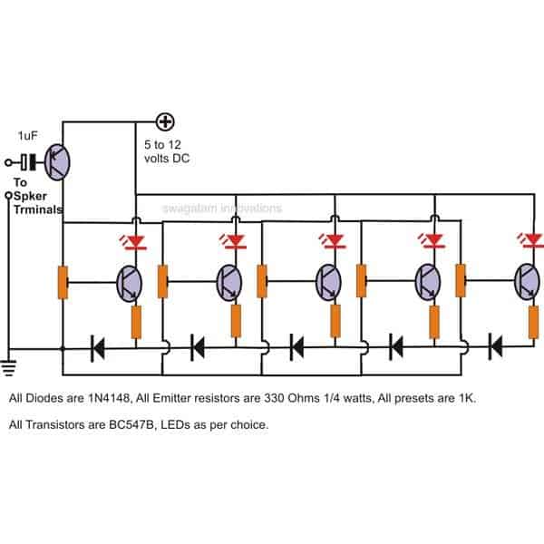
The proposed LED music level indicator circuit may be understood as follows:The components which support the LED illumination are the associated NPN transistor, the emitter resistor, the base preset and the corresponding diode.
The above stage is identical to all the LEDs included in the circuit for obtaining the desired push-pull effect in response to the applied music level at the input.
However there's one difference between the LED stages, though most of the component placement is similar, the diodes form a different pattern.
If you see the circuit closely you will find that the the ground to the first transistor/LED stage from left comes across only a single diode, however the preceding stages ground potential has to encounter the extra corresponding number of diodes in their path.
As we all know that a diode has the property of dropping 0.6 volts, means that the first transistor would conduct much sooner than the second, the second transistor conducts sooner than the third and so on.
Because as the number of diodes increase in the path of the respective transistor, the conduction is inhibited until the the voltage sufficiently increases for bypassing the diodes overall forward voltage.
This increase in voltage can happen only when the pitch of the music increases, giving rise to a sequentially running LED bar graph which shoots forward in response to the pitch or loudness o the applied input music.
The transistor at the input is a PNP and complements the rest of the transistors employed for illuminating the LEDs.
The PNP transistor at the input amplifies the applied low level music signal to levels which is just enough for illuminating the LEDs with reference to the music levels.
Parts List for the explained LED music level indicator circuit
- All NPN Transistors are BC547 = 5
- PNP Transistor is BC557 = 1
- All Diodes are 1N4148 = 5
- All Presets are 10 K = 5
- All resistors are 100 Ω 1/4 watt 5% CFR = 5
- LEDs are 20 mA, 5 mm Red, Yellow, Green = total 5
Formulas and Calculations for the LED Music Level Indicator Circuit
This circuit uses a series of transistors to light up LEDs based on the music signal's amplitude. The components include diodes (1N4148), resistors, transistors (BC547B), and LEDs. The base of each transistor is biased to activate at different signal levels, creating a level indicator effect.
Input Signal Coupling Capacitor (1µF):
The coupling capacitor blocks DC and passes the AC signal from the audio source to the circuit.
Formula for reactance:
XC = 1 / (2 * π * f * C)Where:
- XC = Capacitive reactance (ohms)
- f = Frequency of the audio signal (Hz)
- C = Capacitance (farads)
For example, at f = 1kHz:
XC = 1 / (2 * π * 1000 * 1e-6)
   = 159.15 ohms
This reactance ensures that the capacitor couples the audio signal effectively without significant attenuation.
Transistor Base Biasing (Pre-Set 1k Resistor):
The preset resistor at each transistor's base sets the biasing threshold for each stage.
- The biasing voltage (Vbias) depends on the preset adjustment.
- The transistor turns on when the input signal voltage exceeds Vbias + VBE (base-emitter voltage, ~0.7V).
Emitter Resistors (330 Ohms):
These resistors limit the emitter current (IE) to prevent excessive current through the transistor and LED.
Emitter current formula:
IE = VCE / REWhere:
- VCE = Voltage across the collector-emitter junction
- RE = Emitter resistor (330Ω)
For example, if VCE = 5V:
IE = 5 / 330
   ≈ 15.15mA
This current is sufficient to light up the LEDs one by one.
Diodes (1N4148):
The diodes are connected in series with the base of each transistor. They add a voltage drop (of 0.7V per diode approx), creating a step-wise voltage level for each stage.
Voltage step:
Vstep = Number of diodes * VFWhere:
- VF = Forward voltage of 1N4148 (~0.7V)
For example:
- If 2 diodes are used, Vstep = 2 * 0.7 = 1.4V.
LEDs:
The LEDs light up when the corresponding transistor conducts, The forward voltage of the LEDs depend on their color:
- Red: ~1.8V
- Green: ~2.1V
- Blue: ~3.2V
Working Principle:
- The input audio signal is fed through the coupling capacitor.
- Each transistor stage activates sequentially as the input voltage rises above the biasing threshold as set by the diodes and preset resistors.
- The emitter resistors limit current to protect the LEDs
- The LEDs light up showing the signal level visually.
Using for Festive Seasons
Building your own music controlled Christmas lights may not be as difficult as it may appear to be. In this article I have explained two simple configurations which may be used to decorate a party hall.
No Celebration is Possible without Music Lights
Imagine all those bouncing and dancing lights around you during party nights, shooting up and down with loud music beats, can definitely enhance the ongoing ambiance.
Interested to build one of these at home? A couple of circuits that may be used as music controlled Christmas lights is neatly explained here.
Any celebration or a festival is unthinkable without music and lights, especially when it’s a Christmas party an enhanced ambiance becomes an absolute necessity.
Dazzling, flashing, strobing lights, we have all seen them pretty commonly during celebrations and festive occasions.
However, involving music to lights or rather synchronizing the two together so that the lights flash and follow the music pattern can add entirely a new volume of excitement to the party mood.
Simple Music Light Circuits
The first circuit employs colorful LEDs which when integrated to a music system, interestingly dances forward/backward in a sequential pattern with the applied music intensities.
The second circuit involves mains powered incandescent lamps and produces the same results as above imitating and sequencing with the connected music peaks.
Although the design may appear to be complicated, actually integrating the two parameters is very easy, obviously a bit electronic wiring may be involved.
In many of my previous articles I have discussed LED lights and circuits to illuminate them in many different decorative ways.
In this article I will elucidate how to make arrays of LEDs and mains operated incandescent lamps move and shuffle in back and forth motion in response to the music levels applied at its input.
The attached incandescent lamps may be arranged in rows and columns to produce highly pulsating lighting effect. The effects created by the light arrays responding to the music peaks can simply become a visual treat.
A couple of circuits that may be used as music controlled Christmas lights are discussed below. Let’s understand their functioning through the following explanation:
Circuit Diagram
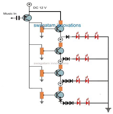
Parts List
- All collector resistors are 1 K = 4
- All presets are 10 K = 4
- NPN transistors are BC547B = 4
- PNP Transistor is BC557 = 1
- All diodes are 1N4148 = 10
- All Triacs are BT136,
- LEDs, 20 mA, 5 mm, color as per preference = 9
Circuit Operation
The configurations are pretty straightforward, looking at the figure, we find that the first circuit involves simple transistor amplifier stages arranged in sequence.
Each stage is comprised of an NPN transistor whose base is rigged into a potential dividing network via a preset. Its collector handles the load in the form of LEDs whereas the emitters are connected to the ground potential through diode or diodes as the sequence is preceded.
Here, the diodes perform an important function of regulating the transistor bias voltage.
Each diode will drop around 0.6 volts across itself and enables the subsequent transistor stages to conduct only as the music peaks tend to reach the appropriate values.
The presets also help to the above function and may be precisely held to positions such that each subsequent stage conducts gradually or sequentially with increasing music peaks.
An input PNP transistor is included to initially amplify the music level available across the speaker terminals sufficiently, so that the light sequencing variations can be optimized over a wider range.
The second circuit which controls mains operated incandescent lamps works quite similarly as above.
However, here the voltage regulation through diodes and zeners is rather employed to the bases of the transistor instead of the emitters, because we don’t want the AC lamps also getting rectified and producing half the illumination.
The base of the each subsequent transistor is offered an incrementing potential drop through additions of more number of diodes and zeners.
However, practically it’s found that it’s absolutely not required, a single diode to each of the bases appears to do the job well as the actual setting of the sequencing pattern is effectively optimized through the presets itself.
The above explained music controlled Christmas lights circuits can be assembled over a piece of general purpose PCB and housed inside the associated amplifier cabinet and powered from there itself.
The output connections to the lamps will however require attention and should be very carefully terminated to the lamps using good quality insulated PVC wires.

Questions & Answers
I have a 12 volt strip of under counter LEDs.I would like to hook up to my biombox to beat to music.I have a tip31 and tried to use that but no luck.can you help me with a circuit that will work.thank you
use TIP122, connect base with music signal through a 1uF/25V capacitor and with a 1K series resistor, connect the LED strip across positive 12V and collector of the transistor, connect emitter with the negative of the supply and also the music negative line.
Thank u sir…*
Few doubts sir…
* In diagram preset value 1k mentioned..
1k or 10k
* For using high power amplifier like stk4141 and mosfet ic…speaker output power will be high , so this circuit itself enough or we want to change transistor and capacitor value…
* There is many pnp transistor but y u choosing 557 only ..pls tell the reason or any other transistor we can use ?
Keasva here are the answers…
1) it's 10K preset
2) for high power input just add a 100 ohm resistor in series with the PNP transistor base capacitor
3) the voltage and current requirement for this application is within the BC557/BC547 range, nonetheless the similar BJTs can also be sued.
Hi engineer, if I don't want to connect speaker, can I use voltage? I want to construct this circuit in multisim and do simulation, but I don't what can I put for the speaker component.
Hi Sharon, sorry I did not understand your question, how can you replace the speaker with a voltage??
hello engr..please how can i get the circuit, i cant find the circuiut
please build the circuit
Can i replace the diodes by 1N4007
yes…will do
Sir Swagatam, Can I use a tip42 at the input section instead a small power general purpose pnp?
sorry tip142 will not give proper results
Sir Swagatam, Can I add this circuit from 5 LED's,transistors and diode's Into 10..
Hi Jenson, yes you can do it.
For more efficient results you can try the IC LM3915 circuit as given here:
https://www.homemade-circuits.com/2012/03/how-to-make-simple-vu-meter-circuit-at.html