Calculating ferrite transformer is a process in which engineers evaluate the various winding specifications, and core dimension of the transformer, using ferrite as the core material. This helps them to create a perfectly optimized transformer for a given application.
The post presents a detailed explanation regarding how to calculate and design customized ferrite core transformers. The content is easy to understand, and can be very handy for engineers engaged in the field of power electronics, and manufacturing SMPS inverters.
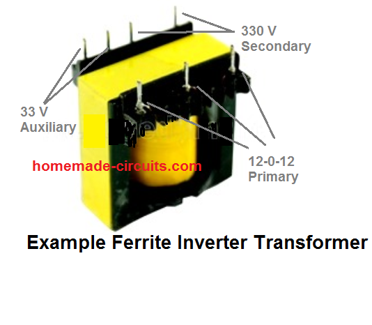
Why Ferrite Core is used in High Frequency Converters
You might have often wondered the reason behind using ferrite cores in all modern switch mode power supplies or SMPS converters. Right, it is to achieve higher efficiency and compactness compared to iron core power supplies, but it would be interesting to know how ferrite cores allow us to achieve this high degree of efficiency and compactness?
It is because in iron core transformers, the iron material has much inferior magnetic permeability than ferrite material. In contrast, ferrite cores possess very high magnetic permeability.
Meaning, when subjected to a magnetic field, ferrite material is able to achieve a very high degree of magnetization, better than all other forms of magnetic material.
A higher magnetic permeability means, lower amount of eddy current and lower switching losses. A magnetic material normally has a tendency to generate eddy current in response to a rising magnetic frequency.
As the frequency is increased, eddy current also increases causing heating of the material and increase in coil impedance, which leads to further switching losses.
Ferrite cores, due to to their high magnetic permeability are able to work more efficiently with higher frequencies, due to lower eddy currents and lower switching losses.
Now you may think, why not use lower frequency as that would conversely help to reduce eddy currents? It appears valid, however, lower frequency would also mean increasing the number of turns for the same transformer.
Since higher frequencies allow proportionately lower number of turns, results in transformer being smaller, lighter and cheaper. This is why SMPS uses a high frequency.
Inverter Topology
In switch mode inverters, normally two types of topology exits: push-pull, and Full bridge. The push pull employs a center tap for the primary winding, while the full bridge consists a single winding for both primary and secondary.
Actually, both the topology are push-pull in nature. In both the forms the winding is applied with a continuously switching reverse-forward alternating current by the MOSFETs, oscillating at the specified high frequency, imitating a push-pull action.
The only fundamental difference between the two is, the primary side of the center tap transformer has 2 times more number of turns than the Full bridge transformer.
How to Calculate Ferrite Core Inverter Transformer
Calculating a ferrite core transformer is actually quite simple, if you have all the specified parameters in hand.
For simplicity, we'll try to solve the formula through an example set up, let's say for a 250 watt transformer.
The power source will be a 12 V battery. The frequency for switching the transformer will be 50 kHz, a typical figure in most SMPS inverters. We'll assume the output to be 310 V, which is normally the peak value of a 220V RMS.
Here,the 310 V will be after rectification through a fast recovery bridge rectifier, and LC filters. We select the core as ETD39.
As we all know, when a 12 V battery is used, it's voltage is never constant. At full charge the value is around 13 V, which keeps dropping as the inverter load consumes power, until finally the battery discharges to its lowest limit, which is typically 10.5 V. So for our calculations we will consider 10.5 V as the supply value for Vin(min) .
Calculating the Primary Turns
The standard formula for calculating the primary number of turns is given below:
N(prim) = Vin(nom) x 108 / 4 x f x Bmax x Ac Here N(prim) refers to the primary turn numbers. Since we have selected a center tap push pull topology in our example, the result obtained will be one-half of the total number of turns required.
- Vin(nom) = Average Input Voltage. Since our average battery voltage is 12V, let's, take Vin(nom) = 12.
- f = 50 kHz, or 50,000 Hz. It is the preferred switching frequency, as selected by us.
- Bmax = Maximum flux density in Gauss. In this example, we'll assume Bmax to be in the range of 1300G to 2000G. This is the standard value most ferrite based transformer cores. In this example, let’s settle at 1500G. So we have Bmax = 1500. Higher values of Bmax is not recommended as this may result in the transformer reaching saturation point. Conversely, lower values of Bmax may result in the core being underutilized.
- Ac = Effective Cross-Sectional Area in cm2. This information can be collected from the datasheets of the ferrite cores. You may also find Ac being presented as Ae. For the selected core number ETD39, the effective cross-sectional area furnished in the datasheet sheet is 125mm2. That is equal to 1.25cm2. Therefore we have, Ac = 1.25 for ETD39.
The above figures give us the values for all the parameters required for calcuating the primary turns of our SMPS inverter transformer. Therefore, substituting the respective values in the above formula, we get:
N(prim) = Vin(nom) x 108 / 4 x f x Bmax x AcN(prim) = 12 x 108 / 4 x 50000 x 1500 x 1.2 N(prim) = 3.2Since 3.2 is a fractional value and can be difficult to implement practically, we'll round it off to 3 turns. However, before finalizing this value, we have to investigate whether or not the value of Bmax is still compatible and within the acceptable range for this new rounded off value 3.
Because, decreasing the number of turns will cause a proportionate increase in the Bmax, therefore it becomes imperative to check if the increased Bmax is still within acceptable range for our 3 primary turns.
Counter checking Bmax by substituting the following existing values we get:
Vin(nom) = 12, f = 50000, Npri = 3, Ac = 1.25Bmax = Vin(nom) x 108 / 4 x f x N(prim) x Ac Bmax = 12 x 108 / 4 x 50000 x 3 x 1.25 Bmax = 1600As can be seen the new Bmax value for N(pri) = 3 turns looks fine and is well within the acceptable range. This also implies that, if anytime you feel like manipulating the number of N(prim) turns, you must make sure it complies with the corresponding new Bmax value.
Oppositely, it may be possible to first determine the Bmax for a desired number of primary turns and then adjust the number of turns to this value by suitably modifying the other variables in the formula.
Calculating the Secondary Turns
Now we know how to calculate the primary side of an ferrite SMPS inverter transformer, it's time to look into the other side, that is the secondary of the transformer.
Since the peak value has to be 310 V for the secondary, we would want the value to sustain for the entire battery voltage range starting from 13 V to 10.5 V.
No doubt we will have to employ a feedback system for maintaining a constant output voltage level, for countering low battery voltage or rising load current variations.
But for this there has to be some upper margin or headroom for facilitating this automatic control. A +20 V margin looks good enough, therefore we select the maximum output peak voltage as 310 + 20 = 330 V.
This also means that the transformer must be designed such that it can produce 310 V even at the lowest 10.5 battery voltage.
For feedback control we normally employ a self adjusting PWM circuit, which widens the pulse width during low battery or high load, and narrows it proportionately during no load or optimal battery conditions.
This means, at low battery conditions the PWM must auto adjust to maximum duty cycle, for maintaining the stipulated 310 V output. This maximum PWM can be assumed to be 98% of the total duty cycle.
The 2% gap is left for the dead time. Dead time is the zero voltage gap between each half cycle frequency, during which the MOSFETs or the specific power devices remain completely shut off.
This ensures guaranteed safety and prevents shoot through across the MOSFETs during the transition periods of the push pull cycles.
Hence, input supply will be minimum when the battery voltage reaches at its minimum level, that is when Vin = Vin(min) = 10.5 V. This will prompt the duty cycle to be at its maximum 98%.
The above data can be used for calculating the average voltage (DC RMS) required for the primary side of the transformer to generate 310 V at the secondary, when battery is at the minimum 10.5 V. For this we multiply 98% with 10.5, as shown below:
0.98 x 10.5 V = 10.29 V, this the voltage rating our transformer primary is supposed to have.
Now, we know the maximum secondary voltage which is 330 V, and we also know the primary voltage which is 10.29 V.
The turns ratio (n) can be calculated as:
n = Vs / VpSubstituting the given values:
n = 330 / 10.29 ≈ 32.1Since the turns ratio is equal to the voltage ratio, the number of turns on the secondary (Ns) and primary (Np) sides must maintain the same ratio.
This relationship is expressed as:
Ns / Np = nConsidering the primary side has 3 turns (Np = 3), we can solve for Ns:
Ns = n * NpSubstituting the values we get:
Ns = 32.1 * 3 = 96.3Therefore we get the number of secondary turns to be approximately 96.3.
The figure 96.3 is the number of secondary turns that we need for the proposed ferrite inverter transformer that we are designing. As stated earlier since fractional vales are difficult to implement practically, we round it off to 96 turns.
This concludes our calculations and I hope all the readers here must have realized how to simply calculate a ferrite transformer for a specific SMPS inverter circuit.
Calculating Auxiliary Winding
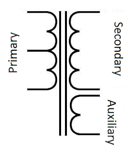
An auxiliary winding is a supplemental winding that a user may require for some external implementation.
Let's say, along with the 330 V at the secondary, you need another winding for getting 33 V for an LED lamp. We first calculate the secondary : auxiliary turn ratio with respect to the secondary winding 310 V rating. The formula is:
NA = Vsec / (Vaux + Vd) NA = secondary : auxiliary ratio, Vsec = Secondary regulated rectified voltage, Vaux = auxiliary voltage, Vd = Diode forward drop value for the rectifier diode. Since we need a high speed diode here we will use a schottky rectifier with a Vd = 0.5V
Solving it gives us:
NA = 310 / (33 + 0.5) = 9.25, let's round it off to 9.Now let's derive the number of turns required for the auxiliary winding, we get this by applying the formula:
Naux = Nsec / NA Where Naux = auxiliary turns, Nsec = secondary turns, NA = auxiliary ratio.
From our previous results we have Nsec = 96, and NA = 9, substituting these in the above formula we get:
Naux = 96 / 9 = 10.66, round it off gives us 11 turns. So for getting 33 V we will need 11 turns on the secondary side.
So in this way you can dimension an auxiliary winding as per your own preference.
Calculating the Wire Thickness
We can calculate the wire thickness by taking into account the current flowing through the primary and secondary windings.
The formula for current is:
Primary Current (Ip):
Ip = P / (Vp * η)Secondary Current (Is):
Is = P / (Vs * η)- Where:
- P = Output power of the SMPS (in watts)
- Vp = Primary voltage (in volts)
- Vs = Secondary voltage (in volts)
- η = Efficiency of the SMPS (typically around 0.8 to 0.9)
The current density (J) is the maximum current a wire can safely carry per unit cross-sectional area.
A typical value for SMPS applications is around 4-6 A/mm².
The cross-sectional area (A) of the wire is given by:
A = I / J- Where:
- I = Current (either Ip or Is)
- J = Current density (A/mm²)
The diameter of the wire can be calculated from the cross-sectional area by using the formula for the area of a circle:
A = (π * d²) / 4Rearranging for d:
d = √((4 * A) / π)- Where:
- d = Diameter of the wire (in mm)
- A = Cross-sectional area (in mm²)
For high-frequency SMPS designs, the RMS current and skin effect must be considered.
The skin depth (δ) informs us regarding how deeply current penetrates into the conductor and is given by:
δ = √(ρ / (π * f * μ))- Where:
- ρ = Resistivity of copper (typically 1.68 × 10⁻⁸ Ω·m)
- f = Operating frequency of the transformer (in Hz)
- μ = Permeability of copper (4π × 10-7 H/m)
For high-frequency designs it is recommended to use multiple thinner wires (litz wire) to minimize skin effect losses.
Now let us see how we can calculate the wire thickness for a 100 W SMPS transformer with the following parameters:
P = 100 W

Vp = 10.29 V

Vs = 330 V

η = 0.85

J = 5 A/mm²
Primary Current:
Ip = P / (Vp * η)Ip = 100 / (10.29 * 0.85) ≈ 11.4 ACross-Sectional Area for Primary Wire:
Ap = Ip / JAp = 11.4 / 5 = 2.28 mm²Primary Wire Diameter:
dp = √((4 * Ap) / π)dp = √((4 * 2.28) / 3.1416) ≈ 1.7 mmSecondary Current:
Is = P / (Vs * η)Is = 100 / (330 * 0.85) ≈ 0.36 ACross-Sectional Area for Secondary Wire:
As = Is / JAs = 0.36 / 5 = 0.072 mm²Secondary Wire Diameter:
ds = √((4 * As) / π)ds = √((4 * 0.072) / 3.1416) ≈ 0.3 mmIf the operating frequency is high (e.g. 20 kHz or higher), consider using litz wire to reduce skin effect losses.
Make sure to use multiple strands of thinner wires with a combined cross-sectional area equal to the calculated area, and avoid using a single thick wire.
Wrapping up
In this post I have explained how to calculate and design ferrite core based inverter transformers, using the following steps:
- Calculate primary turns
- Calculate secondary turns
- Determine and Confirm Bmax
- Determine the maximum secondary voltage for PWM feedback control
- Find primary secondary turn ratio
- Calculate secondary number of turns
- Calculate auxiliary winding turns
Using the above mentioned formulas and calculations an interested user can easily design a customized ferrite core based inverter for SMPS application.
For questions and doubts please feel free to use the comment box below, I'll try to solve at an earliest
More Information can be found under this link:


Questions & Answers
Explained in simple and lucid manner, thank you, sir.
My pleasure Ajay, Glad you liked it!
How do we determine the swg of the coil used
SWG is related to current and can be found by estimating how much current a copper wire with particular thickness can carry. Probably this article can help:
https://www.homemade-circuits.com/56492-2/
Ferrite cores are used NOT because of their high permeability. Actually, ironcores, and especially permalloy cores, etc could showcase permeability exceeding that of typical transformer ferrite cores.
For the reference, effective permeability of typical transformer core ferrites used in SMPS would usually be about 1000 to 2500 or so, depending on application. Gapped cores, like those in flybacks would have effective permeability much lower than that (though it “coupled inductor” rather than “transformer”). However, transformer-grade steel alloys and especially permalloy-like “low-frequency” cores can showcase permeability well around 20 000, more than 10x higher compared to typical transformer ferrites. Some “special” ferrites also expose permeability about 15 000 or more, but are NOT used for transformers, being high-loss things, so only suitable for ferrites. Who needs high-loss transformer? It would just heat itself up, wasting power on that. Avoiding this scenario is pretty much goal of transformer calculations, especially when it comes to ferrite type selection, etc.
But what makes ferrite transformers small? And why we need ferrite? Its mostly about high frequency operation and eddy currents.
Generally, the higher operating frequency is, the more power could be pushed through same transformer size. So if we want small but powerful supply, we have to go for high frequency. At high frequency one can make far less turns in windings, yet they still would have enough inductance to “resist” incoming voltage. The higher frequency, the less turns we need, the smaller transformer we can afford. To certain extent.
What’s the problem with steel, permalloy, etc? Being metallic they are inherently conductive. At which point, core could act a bit like some kind of (shori-circuited) winding, heating itself by eddie currents. This effect could be put in use, giving a rise to “induction heating” – but we do not want it in transformers. So transformer steels are optimized to have relatively high resistance and also split into separate thin plates to reduce eddie currents. However, the higher frequency is, the more pronounced this “induction heating” gets – and even special steel alloys and very thin plates aren’t enough to prevent core heating. That’s where ferrites come into play. They are ceramic materials, so unlike metals they show rather poor electric conductivity. At which point eddie current loses are mostly mitigated, so we can increase operational frequency a lot compared to steel designs. This implies far smaller windings, so we can push way more power without increasing transformer size. So SMPS would have unusually small ferrite transformer for given power, compared to low-frequency steel transformer designs.
As for topologies, there’re a bit more options. Out of bridge-like, there’re three: half-bridge, full-bridge and push-pull. Half-bridge and push-pull are similar in overall idea, but implementation is different, half-bridge uses just 1 winding and some capacitors to expose winding to both polarities. Push-pull rather uses different halves of winding to achieve same result (in terms of magnetic field behavior). This brings different tradeoffs, and full bridge lacks most shortcomings of both – but being more expensive due to 4 high-voltage transistors reqirement.
Some relatively recent power supply designs could also use e.g. “2-switch forward” approach, which also uses 2 MOSFETs but operates in somewhat different manner. It underuses transformer core, magnetizing it in just 1 polarity, but on other hand it gets favorable MOSFETs voltage and current tradeoffs, pretty much like full bridge, being cheaper solution. So it fairly usual to see 2-switch forward in e.g. ATX power supplies up to about 800-1000W or so. Transformer computed much like “usually”, but with some special considerations in regard of saturation & demagnetizing attached.
There’re also flybacks, that aren’t even transformers by their actions, though turns ratio still haves some meaning. These have their own limitations but are cheapest option up to around ~100W of output power. Above this point different topology could be better consideration though.
Thank you for the nice explanation!
> being high-loss things, so only suitable for ferrites.
Oh, I meant high-loss high-permeability ferrites are used in EMI filters, etc, where turning noise into heat is rather something good.
Also it worth to mention there is approximately the following trend: the higher intended opreational frequency of ferrite compound is, the less permeability it would get, the higher resistivity it would enjoy, it would have lower core losses but require more turns.
As example, think of N49 vs N67, for example. N49 is tailored up to about ~1MHz or even more, while N67 is barely ok up to maybe 200kHz at very most. N67 would have higher permeability, but would get far higher core losses at high frequencies. Overall it comes to trading copper loses vs core loses, in perfect world we would try to hit minimum of their sum, however numerous secondary considerations make it challenging.
Thank you Mr. Swagatam for your reply. Can I understand some better?
Please, what do you mean by Half bridge and full bridge both can work with two wire primary?
Can you explain what this means with the aid of a diagram also?
Thanks
Hello Victory, please read the last sections of this article:
https://www.homemade-circuits.com/how-to-design-inverter-basic-circuit/
It explains about half bridge and full bridge topology in brief.
Please did you mean that you divide into half the value gotten for the primary winding calculation because it’s a push-pull topology?
For example, a primary winding calculated as 20turns will then be divided by 2 to give 10turns because it’s push topology?
You must double it for a center tap topology. if the result is 20 turns then for a center tap transformer primary it will be 40 turns with center tap at 20th turn
Pls can I understand better the what happens in half-bridge, full-bridge and pull-pull connection of ferrite transformers clearly with a bit of diagrams, if possible?
And also, can a ferrite transformer when operated on pulsed DC, still possess reactance to resist voltage and current as would a normal transformer in order to avoid a short circuit when connected to the power supply? Thanks
Half bridge will pass current in only one direction across the primary winding. A full bridge will pass current alternately across the winding in reverse forward way. The output of a half bridge will be a half wave AC, whereas in full bridge it will a full wave AC.
Half bridge and full bridge both can work with two wire primary.
A center tap push pull topology is also a full bridge topology but it requires two winding at the primary with a center tap.
A pulse Dc operation is another form of half bridge operation,and it is possible but the output will be half wave AC.
Pls Mr Swagatam, can you help me explain why a capacitor is connected in series with the transformer in the circuit shown from the link below?
http://tinypic.com/view.php?pic=ne9sow&s=9
I understand half bridge transformer connection partially, having read your article about it. But, in the conventional connection used for half bridge transformer connection, there are two capacitors, but in this circuit, only one was used. Why? Does the capacitor act as a power bank, storing power temporarily, to be used for the other half circle when the transistor beneath is switching?
And also, does the capacitor reduce the voltage coming to the transformer?
The circuit shown in the link is not a push pull topology, therefore only a single capacitor is used. Capacitor will reduce the current, not the voltage, higher value capacitors will produce higher current.
Dear Mr. Swagatam
Thank you for sharing this helpful discussion.But may you discuss about selecting wire tickness (AWG) and wiring transformer(for example first wiring primary then secondary …) due to output current of SMPS?
Thank you
Dear Reza, wire gauge can be estimated with some trial and error (approximation), or you can refer to the table which is given i this article:
https://www.homemade-circuits.com/56492-2/
Normally the higher voltage winding is wound first and then the lower voltage on top of it, with a layer of insulation.
hello Mr. Swagatam!
Thanks for the ferrite core transformer calculation. I have seen this same calculation for ETD39 ferrite core transformer in more than 3 blogs. And when i take the idea of the Bmax of 1300G to 2000G for bigger size ferrite like EE65 ferrite with Ae = 540 millimeter square = 5.4 centimeter square, I ended up getting funny number of turn(s) like 1.7Turn = 2Turns approx for a primary voltage of 24V, a frequency = 50KHz, Bmax = 1300G, and Ae=5.4 centimeter square. And since 1300G is the lowest range of the spec (i.e 1300G – to – 2000G), if i say let me adjust the Bmax to something like 1500G so as to be within the middle region of the Bmax spec, the I got 1Turn approx for primary winding.
You know the funniest thing here? the leftover spaces in the transformer can still accommodate like 5Turns for the primary even after considering the secondary. And being a large size ferrite core transformer, I need to have it well wound by ensuring there is no gap between the cores and the winding to avoid excessive losses.
For this reason therefore, I tried to recalculate for Bmax using N-primary = 5Turns and I got Bmax to be 444.444 = 444G approx. So, my question is can Bmax be reduced to such small value for a large ferrite core transformer?
Thank you my mentor for your expected response.
Hello Kingsley, If all the parameters are correctly selected then the turn number will be correct, but if one of the parameters is wrongly selected then the turn numbers can go wrong. Are you sure EE65 is correct, and also the thickness of the wire that you may have selected?
Bmax = 444 will not work as per the rules, so you cannot change that, instead try changing the other parameters which could be perhaps wrongly selected.
Good to here from you my dear motivator.
For the parameters, EE65 is a large ferrite transformer. with all the research i have made, the Ae=540mm square which by conversion is equal to 5.4cm square. For other parameters such as frequency, I chose F=50000Hz, V-in(norm) = 24V, and Bmax = 1500G, yet I got 1Turn for N-primary.
so my calculation was as follows:
N-pri = (24*10^8)/(4*50000*1500*5.4)
Again, I observed that the larger the size of ferrite core transformer, the larger the Ae in mm square. And this is one problem why the Number of turn is drastically reduced. If any parameter spec for the EE65 is wrongly selected, then it should be the Bmax since the datasheet declares Ae to 540mm square.
Hope I am correct saying that 540mm square = 5.4cm square? Or am I wrong? please correct me if i am wrong.
if i should refer your question in the above reply i.e “Are you sure EE65 is correct, and also the thickness of the wire that you may have selected?” I used 10 strands of 20AWG copper coil for the Primary side (i.e 24v battery side) and 5 strands of the same copper coil on the secondary side (330Vac side). Yet 1Turn is too small and enough space still exist in the window area.
Hello Kingsley,
The formula results are dependent on the turn ratio between the primary and the secondary, and also the E core selection. If your wire thickness and turn calculation are not correct then the core size will also be not correct, and this will ultimately result in the whole calculation going wrong.
How much space is left is not relevant to the number of turns on the primary.
By the way using 20 AWG for the 220V is grossly wrong, how can you have a 330V winding wire having the same thickness as the 24 V primary, that too 5 strands together…? I think this is main problem behind the wrong primary turn results.
Please divide the primary wattage with secondary voltage to get the secondary current and then you can estimate the wire thickness accordingly.
Ok, I want to ask if the ferrite core transformer will be OK at the frequency of 27KHz since the range of frequency specified is between 20KHz to 500KHz? If that can be fine, then reducing the frequency will take care of the wrong number of turns while still maintaining the Bmax within that same range of 1300G to 2000G; since I can now Obtain up to 2Turns for the primary Turn.
yes 27kHz will work, but using similar SWG wires for primary and secondary would still be wrong, considering the fact that primary is 24V and secondary 330V, the wire must also proportionately vary in thickness.
OK since using the same size of AWG but different number of strands won’t work, can you please suggest me the right AWG for the primary and secondary? Again can you also suggest me the quantity of strands for each?
Thank you sir.
Strands won’t be required for the secondary, since the wire itself will be quite thin. the secondary wire must be 15 times thinner than the primary, considering 24V is 15 times smaller than 310V
Ok, My boss! I will consider doing it as you have said. Thank you dear.
Is it safe to remove the capacitor?
And if you did, will the circuit still work?
If the primary is wound with correct calculation then you can remove the capacitor, otherwise it can burn the MOSFET
1. That’s with the capacitor connected in series with the transformer, does it help to provide inductive reactance?
2. And if so that it helps to provide inductive reactance, removing the cap then, where will the inductive reactance come from since current will only flow in only one direction when the cap is removed because the cap is charged and discharged through the transformer?
Capacitor works like a series resonant circuit for optimal performance of the inverter
dear sir! can this formula ” Ns(pri) = ((Vin * 10^8)/(4 * Bm * fosc * Ae)) can be used for winding smps transformer for single power mosfet smps based on uc3842 etc?
Dear Sheraz, it can be used according to me!
dear sir! i ‘m using power Esim software for designing smps xformer. i have problem mostly by identifying diameter of secondary turns wire (turns for output voltage let say 16v). they show that N2 = 4 (0.18mm x 7T/W x 9). sir i understand that there are 4 output turns each turn having 9 parallel wire but don’t understand the concept behind (0.18mm x 7T/W)? i don’t know what they mean???
Dear Sheraz, diameter and number of strands is directly proportional to the current specification of the transformers or the secondary of the transformer. Higher current will require proportionately thicker gauge wire and number of strands
it means that there are 7 strands of wire having diameter 0.18mm and each (0.18mm x 7T/W) must be considered as single wire for higher current and then 9 such wire must be winded in parallel for 4 turns?
That’s right, 7 strands together must be considered as single wire for the winding.
Not to pick it apart but 125mm ^2 is 12.5cm^2. This same thing is pretty much wrote over here with the same mistake for an ETD39.
Can you please elaborate a little more on this?
No need, I am wrong. I was reading these articles with idea there are 10mm in a cm, But then I looked it up and there are 100mm^2 per centimeter. Didn’t know that. I would delete this if I could. Sorry to trouble you.
No problem, thanks for clarifying!
Hi thank you for this post i need to know why you said in your post the transformer you had chose has a 250 W but when i read in the datasheet i find that the ETD39 transformer had 450 W
Hi, the recommended size may have a range between 250 and 450 watts, it cannot be a fixed value. Depends how well the winding is optimized
Hello, am interested in ferrite inverter transformer, pls is there any way I can be getting them?
Hello, I think you can get a complete ferrite core based converter kit from ebay.
Hi swagtam. If u are to use the transformer for a 12v battery should it not be 9v-0-9v center tap? The diagram shows a centertap transformer but u calculated for single 10.5v.
Hi Evergreen, the calculation is not critical, because the output voltage range is not critical and can be anything between 210 V to 240 V.
10.5 V is used because the lowest battery level is taken as 10.5 V here. The transformer primary can be anywhere from 9V to 11V
My main question is, will it be a center tap or a single? If it is a center tap will it be 9V-0-9V (18V) or 4.5V-0-4.5V (9V) For a 12v battery? And is the aux a must for a ferrite transformer?
I have already answered. it can be anything between 9 and 11V, center tap or not depends what kind of inverter topology you are using. For the aux winding details please read the auxiliary section of the article.
9 means 9-0-9, 11 means 11-0-11 for center tap.
for full-bridge this will be 0-9V and 0-11V
Thanks a lot swagtam, i got it now.
Sorry for the mutiple questions swagtam, but in the feedback aspect of the article, i was thinking if it means to add the other feedback system found in the feedback link, using 555 timer ic? Simply put should i add the 555 ic feedback system to my ferrite transformer inverter?