In this article I have explained regarding how to connect and illuminate a few 5mm LEDs using a 3.7V Li-Ion cell, normally used in cell phones.
I keep receiving requests from the readers who seem confused with the connection details of 5mm LEds with a 3.7V Li-ion cell. The requests inspired me to write this post, hopefully it would answer the many related queries.
Using a Cellphone Li-ion Cell
Since standard 3.7V Li-Ion cells which are normally used in cell phones are rated at around 800 to 1100mAh, are quite capable of supporting a few 5mm LEDs, and would be able to keep them illuminated for quite sometime.
A normal 5mm white LED requires about 20mA current at 3.3V for getting illuminated optimally.
The circuit involved for illuminating 5mm LEds through a 3.7V Li-Ion cell is actually too simple, primarily because the parameters are closely matched with each other.
Here, connecting the 5mm LEDs in series wouldn't be feasible because the maximum volts from the cell is just 3.7V while even two LEDS in series would call for above 6V.
Therefore the only option left is putting them in parallel.
Ideally when parallel connections are involved, a series limiting resistor becomes imperative with each LED in the array. This helps ensure uniform light distribution or emission from the LEDs.
However it's not an absolute requirement, especially when the driving voltage is close to the forward voltage of the LEDs.
Also taking the simplicity factor into account, a single limiting resistor may be used in such cases and therefore here too we have eliminated individual resistors.
How to Connect the LEDs
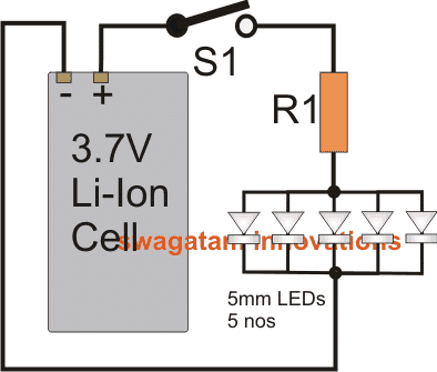
The circuit diagram below shows a simple configuration comprising of a 3.7V Li-ion cell, 5nos 5mm LEDs and a limiting resistor R1. The procedure shows how simply a Li-ion cell may be used for illuminating 5mm LEDs for a reasonably long period of time.
Each LED is supposed to consume 20mA current, therefore 5nos would together consume around 100mA, therefore R1 may be calculated as follows:
The Formula
R = (Supply voltage - LEd forward voltage)/LED current
= (3.7 - 3.3)/100 = 0.4/0.1 = 4 ohms.
The required wattage would be 0.4 x 0.1 = 0.04W, so a 1/4 watt resistor would be more than enough.
Assuming the cell to be rated at 800mAH, with 5 LEDs, the approximate back up time available from the cell could be calculated using the following cross-multiplication.
800/100 = x/1100x = 800x = 800/100 = 8 hours ideally.
However practically you would find the above calculated back up time to be considerably less due to many inherent inefficiencies associated with the system or the circuit.
More LEDs can be added, if you are ready to compromise the backup time proportionately.



Questions & Answers
Hi, who much voltage and current a 10 mm led require. I want to connect 4 10mm led to 12v bike battery in parallel. How much ohms resistance should I give. Whether parallel or series connection is optimum.
Nobody can tell as there are thousands of different LEDs – you’d have to look up your particular LED and its specifications.
Hi, here are the details:
3.0-3.4VDC Forward Voltage
80mA Forward Current
30 degree viewing angle
16,000-20,000 MCD output
connect them in series, use a single 10 ohm resistors, 1/2 watt
how to add auto charging and auto on/off LEDs when charger is plugged in
Resistors measured in Watts? What???
Hello, Swagatam. I like your blog very much.
But you are wrong, the resistor is not at 3.3V, but it is under 3.7 – 3.3 = 0.4V, and the power it manages is 0.4 x 0.1 = 0.04 W
Then, the resistor may be 1/8 W or less.
Regards.
thank you Harry, yes that's a typographical error by me.
The wattage is always equal to potential difference across the resistor multiplied by the current flowing through it, that's simple Ohms law
I'll correct it soon
Hai iam have 3.7v nokia battery and also have 3v bulb iam light a bulb easily but please tell what problem cause if i not vonnect a ohm resistance and also tell what type v resistor i need to light a 3 v bulb using 3.7v battery please help me thank you
Hi, you won't require a resistor for a bulb, resistor is required only for LED….still for better safety you can use a 1 ohm resistor in series
Hi, the problem is caused due to their higher FWD voltage drop rating than the other LEDs in the group.
You must add resistors to each and every LED through proper calculation, as per the following formula:
R = Supply voltage – LED optimal FWD drop rating / LED's safe current rating
for example, for blue the above formula would go in the following way
R = 3.7 – 3.3 / 0.02 = 20 ohms
I think one drawback when you’re connecting LED in parallel is if one burn out the rest not emitting light.
In parallel connection even if one of the LEDs burn others will remain illuminated, however today the LED quality has improved a lot and they will not get damaged as long as the specifications are correctly maintained, regardless of whether they are connected in series or parallel.
Hi Swagatam,
Your blog and explaining technique is very good. I learnt a lot about powering LEDs. Thank you.
I need some help from you about my emergency light project which powered from 18650 x 2 batteries (3.7 v + 3.7v). I would like to glow 20 led (white bright) using parallel circuit. Please help.
Thank you Sunil, glad to know you liked my site.
Here’s the formula and calculations:
Assuming you want to illuminate 5mm LEDs high bright type LED with 20mA current each, 20 of them in parallel would consume 20 x 20 = 400mA or 0.4 Ampere.
The formula for calculating the current limiting resistor is:
R = (Supply voltage – LEd forward voltage)/LED current
R = (3.7 – 3.3) / 0.4 = 1 Ohm
wattage will be (3.7 – 3.3) x 0.4 = 0.16 watts or simply a 0.25 watt standard resistor could be used
for the emergency light circuit you could tr the following concept
https://www.homemade-circuits.com/how-to-make-efficient-led-emergency/
A single limiting resister can be used or not, when a 5V, 1A, 10400mAh output powerbank is used as a source.
Single resistor is enough if the LED specs are identical.
Thanks
Greetings, sir. I want to connect a flash LED like what the cell phones use to a 3.7v battery equally the one used by cell phones, which resistance recommends me to use in this case? First hand thank you very much
Hi Juan, different mobiles have different ratings for the flash LED, so you will have first confirm the current rating of the LED, then I can suggest the resistor value.
sir, Greetings..
i tried several times with this formulae but failed .i use only 5 led.The problom is when after charging the lion battery output voltage should 4.2 volt then this voltage pass through led immediately burn one or two leds.Anyway to maintain constant current irrespective of voltage?expecting your valuable reply.
Sison, I have tried this in many applications and has worked without any problems, in fact all cheap emergency lamps use the same concept. If it is not working for you then better use each resistor separately for each of the LEDs. Use the same the formula for calculating the values. In the formula the current will now reduce since a single LED is being calculated.
Hello, I am try to find a way to avoid expensive Owl predator flashing lights–My knowledge of electrical mini devices is limited to + and –
I bought some red flashing led diodes, I would like to wire in a photocell and use a solar charging system with a rechargeable 3.7 battery as power-
I do not understand the electronic schematics and their icons. think You all might show me in a + and neg.- graphic (pencil drawing) the circuit I could solder my pieces into place.You may not have time .to decipher this writing.
Hello, you can configure the LED solar panel with a transistor to achieve your idea, as shown below:

Hello, I would like a diagram of a solar dusk to dawn light. The goal is using the smallest solar panel, one bright white led that produces 55 lumens with a 18650 3.7v battery. The light should last every night 10-12 hours. Any help would be greatly appreciated.
Hi, you can probably try the last circuit from this article with some minor modifications:
https://www.homemade-circuits.com/solar-garden-light-with-programmable/
Greetings Swagatam. I stumbled on your technically inspiring article about how to connect a 5mm led light to a 3.7v. li-on cell battery. I am a DIY enthusiast with keen interest on electrical concerns. I am not a pro.
My search for some explanation for reason why 2pcs of 3.6v rechargable 2032 coin cell batteries blew up each led bulb (two reading glasses lamps) one after the other. Normally the forward voltage of the led lights needed to power the mini led bulb is 2 pieces 3.0v. li-on coin cell batteries.
Please shed some light on this case for this and other learners. Is 3.6v rechargable coin battery too powerful for a single 3.0v power 5mm led light?
Secondly, I noticed that when both coin batteries are placed together in series as should be loaded in the led lamp battery compartment, there is tiny spark at contact. Is this normal?
Thanks.
Thank you Bernardese, Glad you liked the post.
An LED can blow due to two basic reasons, either an over-current or overheat. An Over voltage can also burn an LED, but only if it is backed up with high current. If the current low, then over voltage cannot affect the LED since the voltage would never rise and drop to the LED level, due to low current.
In your case, the li-ion cell has a very high current content, which means even at 3.7 V, it can drive the LED in an over current situation, because 3.6 V is 0.3 V higher than the optimal 3.3 V limit of the LED. Moreover, the 3.7V li-ion when fully charged can reach upto 4.2V which is extremely high for any 3.3 V LED.
That is why a series resistor is required for limiting the current to the LED and to safeguard it from over current.
If your LED is a power LED, like the 1 watt LEDs, then along with a resistor you will also need to attach an heatsink to the LED to safeguard it from over heat, and thermal runaway.
…the sparking is not normal, it simply shows that your LED is consuming abnormally high current
Hi Swagatam, Very new to this, first project with Lipo, still much to learn. I’m attempting to build a 5S2P pack for a power tool. Cells are new, capacity tested but not matched. I would like to get 4000mAh out of each 2P. Would I be able to parallel cells of slightly different capacities as long as they total the 4000mAh I’m looking for from each pair? For example, parallel a 1970mAh cell with a 2030mAh cell and a 1985mAh cell with a 2015mAh cell, each pair to produce the necessary 4000mAh? Thanks much!
Hi Mike, that’s possible, you can easily put batteries in parallel with different mAh ratings, provided their voltage rating are similar.
I am trying to drive an LED holiday display using a 3.2v LiFePo4 cell. The catch is that the display has strands with some of the LEDs in a forward voltage configuration and some in a reverse configuration. In order to light all of the LEDs the polarity of the leads feeding the strands goes from positive to negative quickly enough to make them all appear to be lit at the same time. The white LEDs light well at 2.6v and draw 15mA. I am at a loss as to how to design a circuit that can change the polarity of it’s output. Can you help? Thanks!
If the reverse forward LED strings are connected in parallel, then you can feed an AC voltage to the strings through an appropriately calculated resistors so that all the LEDs appear to be illuminated simultaneously.
Thank you for your reply and the solution to my issue. The LED strings are connected in parallel. I will now try to figure out a circuit to do this. You are providing a wonderful service to all of us trying to make our projects work. Thanks again!
Thank you, hope you are able to figure it out soon..
Hi Swagatem,
Lots of good info here, thanks.
I would like to recell some 3 volt flashlights with Lipo cells connected in parallell, nominal voltage 3.7, initial voltage 4.2 to power 3 volt LED. Is this too much power for the bulb please?
Thanks,
Mike
Hi Mike,
Yes a fully Lipo cell may reach up to 4.2V, which is too high for a 3.3 V standard LED. You will have to connect a series resistor with the LED to limit the current.
Considering a 3.3 V 20 mA LED. The resistor value will be:
4.2 – 3.3 / .02 = 25 ohms 1/ 4 watt
Once this resistor is connected, you can add any number of cells in parallel, that will not matter.
If I connect three LEDs in parallel together with 3.7v lithium battery, what value of resistor can I connect with it to obtain bright light and still prevent the LEDs from being burnt?
Ideally you must have one individual resistor for each LED, but if you want to have a common resistor for all the parallel LEDs, it is also possible. You can calculate the resistor value using the following formula:
R = Supply voltage – LED Forward voltage / Total LED current
Thanks for your response sir. But I’ve done that calculation before and I got 20ohms but when I used 20 ohms resistor with three LEDs (connected in parallel) and 3.7v lithium battery, the light is not as bright as it supposed. Thanks
Assuming the current of each LED is 20 mA, for 3 LEDs in parallel the total current becomes 60 mA. The full charge voltage of the Li-Ion cell will be 4.2V. Thus, the equation can solved in the following manner:
R = 4.2 – 3.3 / 0.06 = 15 ohms
Did you follow the above method, the result will be absolutely correct using this method.
Can an outdoor security lighting system consisting of 8 high power LEDs each individually separated from a 3.7 volt lithium ion battery bank by 100 feet of 14 ga copper wire work?
Can’t say without practically checking it, because the resistance of the 100 feet wire is not known.
I used 16 number of 5MM led with 4v rechargable battery which is charged by solar panel. do inneed to use resister?? and which one?
Yes, with 4 V you must have a resistor for 3.3V LEDs. The formula as given below:
Resistor = 4 – 3 / LED Current.
If your LED current is 20 mA then:
Resistor = 4-3 / 0.02
= 1 / 0.02
= 50 ohm
So you must use a 50 ohm resistor in series with each of the 16 LEDs.
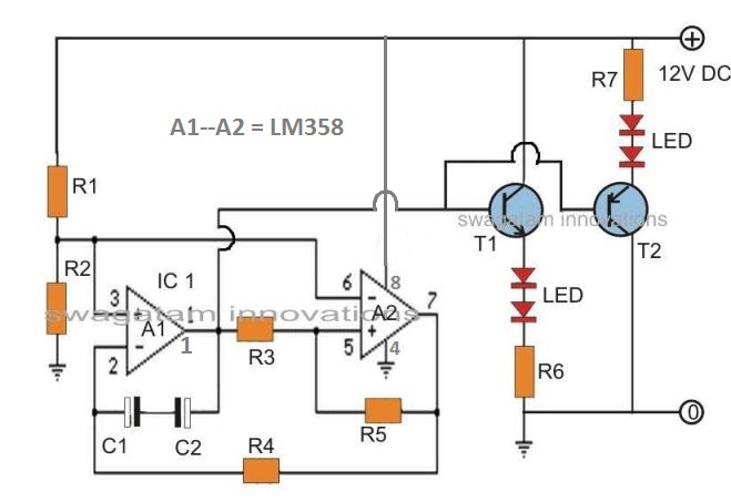
Please send me a solar powered 3.7 v LED flip flop circuit diagram. Thank you
Try this circuit, connect it to a 5 V solar panel
Hi Swagatam, I was inspired by what I have read. I have a particular situation I have been unable to solve. If you could help it would be appreciated more than you can imagine. Picture if you will, 4 red leds in parallel powered by 2 aa batteries. I need to add a switch and circuit to the existing that will allow a regular flash of said leds. if you see a second switch causing flash the first switch a constant light
Hi Mike, I think you can try the following design and see how it works:
Thank you for your prompt reply. I assembled this circuit this morning. Unfortunately I could not make it work as intended. I will continue to ponder the question as to where I went wrong.
If you will I am trying to conform to existing legalities with existing lighting. Thank you
Mike