• Skip to main content
  • Skip to primary sidebar

Homemade Circuit Projects

Need circuit help? Post them in the comments! I've answered over 50,000!

Blog | Categories | About | Hire Me | Contact | Calculators-online
You are here: Home / Meters and Testers / High Voltage Meter Circuit [for Measuring 10kV]

High Voltage Meter Circuit [for Measuring 10kV]

Last Updated on June 8, 2026 by Swagatam 8 Comments

In this article I have explained a simple high voltage meter circuit which can be used for measuring extremely high voltages in the order of many 1000s of volts.

Table of Contents
  • Circuit Description
  • Calibration
    • Power Supply

The circuit can be used to measure high voltages from

  • CDI units,
  • Automobile spark plugs,
  • high voltage generators,
  • mosquito bat circuits,
  • fence chargers,
  • room ionizer circuits etc.

Circuit Description

The voltage detecting IC CA3140 is a MOSFET input op-amp with the ability to measure voltages below the negative supply rail, which eliminates the need for dual supplies. A single IC allows us to  construct a circuit which can measure up to 10,000 volts without adversely effecting the circuit, thanks to the extraordinarily high input resistance of 1000 Meg Ohms (R1 to R10) attached to the probes of the FET op-amp.
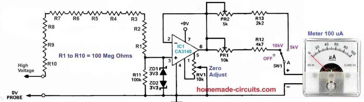
The voltage across R11 is reduced to a acceptable level through resistors R1 to R10 (100 Meg each). This stepped down voltage is detected by IC1 and supplied at its output to the current meter for displaying the high voltage. IC1 is wired as a voltage follower, which means it outputs the same voltage which is detected across R11 (its input). As a result, it serves as an impedance converter, supplying power to the 100uA meter.

This meter is connected via a series resistor which can be appropriately adjusted to convert the ammeter into a voltage meter that reads in kilovolts.

Calibration

The calibration procedure is quite easy. Start by adjusting the meter to zero using the RV1 preset. This is done by keeping the probe tips shorted and by keeping the meter on the 5kV range through the SW1 switch.

Next, switch the meter on the 10kV range through the SW1 and simply put a 1V DC supply across R11.

After this, adjust PR1 until the meter needle reaches to a full scale reading of 10kV.

Now, adjust SW1 back on the 5kV range and connect a 0.5 V DC across R11 and adjust PR2 until a full scale deflection is achieved on the meter corresponding to a 5 kV on the scale. The meter dial can be graduated with calibrations of 0-10kV in 1 kV steps on the upper side of the meter, and create markings of 0-5kV in 1kV steps on the lower side, just below the 10kv graduations.

Power Supply

The power supply DC for this high voltage meter circuit can be derived from any ordinary 9V PP3 battery, or a regulated 9V DC from a AC to DC adapter.

You'll also like:

  • MOSFET TESTERSimple MOSFET Tester and Sorter Circuit
  • LED sig meter 2RF Signal Meter Circuit
  • rtd 2RTD Temperature Meter Circuit
  • function generator circuit10 Useful Function Generator Circuit Diagrams Explained

Filed Under: Meters and Testers Tagged With: 10kV, High, Measuring, Meter, Voltage

About Swagatam

I am an electronics engineer and doing practical hands-on work from more than 15 years now. Building real circuits, testing them and also making PCB layouts by myself. I really love doing all these things like inventing something new, designing electronics and also helping other people like hobby guys who want to make their own cool circuits at home.

And that is the main reason why I started this website homemade-circuits.com, to share different types of circuit ideas..

If you are having any kind of doubt or question related to circuits then just write down your question in the comment box below, I am like always checking, so I guarantee I will reply you for sure!


Previous Post: « Parametric Equalizer Circuit
Next Post: Echo Effect Generator Circuit »

Reader Interactions

Questions & Answers

Total Posts: 8
Newest Oldest
Miguel
August 8, 2024 • 2 years ago #157556

Good Morning

What is the dissipation power of the resistors?

Is the battery negative connected to the circuit negative?

Reply
SwagatamAdmin
August 8, 2024 • 2 years ago #157558

Hello Miguel,
all the resistors can be rated at 1/4 watt 1% MFR.
Yes, the circuit negative must be connected with the DC supply negative.

Reply
Miguel Adilson Secco
August 14, 2024 • 2 years ago #158004

Ok, thanks

I’m going to adapt a multimeter galvanometer

Reply
SwagatamAdmin
August 15, 2024 • 2 years ago #158030

ok, no problem…

Reply
Vikas loh
October 25, 2024 • 2 years ago #164344

hii I tried using 1/4 watt resistor earliear.
I don’t know value of resistor today ,principle is same ratio of voltage divider is 1000:1,but all resistor are burn due to high voltage spark is between two legs of resistor and resistor is dead.

now I make 20nos resistor of 2 Megaohm 1watt and 200k resistor at last. and out put of this 200k is give to oscilloscope.it works fine.,

Reply
SwagatamAdmin
October 26, 2024 • 2 years ago #164386

Thank you Vikas,
I am glad finally you could finally solve the issue.

Reply
suat
July 4, 2024 • 2 years ago #153394

Hi Mr. Swagatam,
As known there is a distribution coil at the car. I think they can produce about 70Kv voltage but low current. If we use 220V AC bulb to test it what
the result would be? The bulb may be burnt or no light due to weak current. Could you share your comment about the matter? Thanks

Reply
SwagatamAdmin
July 4, 2024 • 2 years ago #153399

Hi Suat,
I think if the power (watts) of the 70kv is lower than the watt rating of the bulb then the bulb might not burn, and may produce a proportionate amount of glow.

Reply

Need Help? Please Leave a Comment! We value your input—Kindly keep it relevant to the above topic! Cancel reply

Your email address will not be published. Required fields are marked *

Primary Sidebar


Categories

  • Arduino Projects (95)
  • Audio and Amplifier Projects (134)
  • Automation Projects (18)
  • Automobile Electronics (103)
  • Battery Charger Circuits (89)
  • Datasheets and Components (109)
  • Electronics Theory (150)
  • Energy from Magnets and Earth (40)
  • Games and Sports Projects (11)
  • Grid and 3-Phase (20)
  • Health related Projects (27)
  • Home Electrical Circuits (13)
  • Indicator Circuits (16)
  • Inverter Circuits (100)
  • Lamps and Lights (163)
  • Meters and Testers (72)
  • Mini Projects (28)
  • Motor Controller (68)
  • Oscillator Circuits (30)
  • Pets and Pests (15)
  • Power Supply Circuits (91)
  • Remote Control Circuits (50)
  • Security and Alarm (65)
  • Sensors and Detectors (107)
  • SMPS and Converters (46)
  • Solar Controller Circuits (62)
  • Temperature Controllers (44)
  • Timer and Delay Relay (50)
  • Voltage Control and Protection (44)
  • Water Controller (37)
  • Wireless Circuits (31)


Circuit Simulator

circuit simulator image


Subscribe to get New Circuits in your Email


Other Links

  • Privacy Policy
  • Cookie Policy
  • Disclaimer
  • Copyright
  • Videos
  • Sitemap

People also Search

555 Circuits | 741 Circuits | LM324 Circuits | LM338 Circuits | 4017 Circuits | Ultrasonic Projects | SMPS Projects | Christmas Projects | MOSFETs | Radio Circuits | Laser Circuits | PIR Projects |


Recent Comments

  • Swagatam on 2 Cool 50 Watt Inverter Circuits for Students and Hobbyists
  • Swagatam on The Perfect FM Radio Circuit using TDA7000 IC
  • Swagatam on 9 Simple Sine Wave Generator Circuits Explored
  • way on 2 Cool 50 Watt Inverter Circuits for Students and Hobbyists
  • Athull on The Perfect FM Radio Circuit using TDA7000 IC

Social Profiles

  • Twitter
  • YouTube
  • Instagram
  • Pinterest
  • My Facebook-Page
  • Stack Exchange
  • Linkedin

© 2026 · Swagatam Innovations