We all use remote control handsets for controlling various household devices such as TV, AC, Music systems, curtains etc, and sometimes we seem to have problems with these devices, or even a newly purchased remote controller unit occasionally seem to malfunction, and identifying the issue becomes quite difficult for us.
This simple 2 transistor infrared tester circuit will allow you to check the response of any remote control handset and help you to verify whether or not it is working OK, or needs to be replaced with a new.
Most of the time a low battery or a loose battery connection becomes the main issue which causes a remote handset to malfunction, however if you have a new battery installed and still the device doesn't work efficiently then perhaps this simple remote tester circuit could be used for identifying the fault.
Using a Two Transistor Circuit
Circuit Diagram
Video Clip
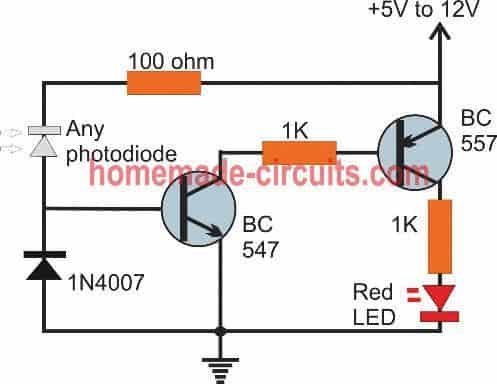
A simple TV remote infrared tester circuit using just 2 transistors can be seen in the above figure. The working of the design is self explanatory.
When the remote control handset's button is pressed and pointed towards the photodiode of the circuit, the photodiode begins conducting and allows a few mV to pass through it.
These tiny electrical signals in the form millivolts reach the base of the NPN BC547 which responds to these signals and in turn begins conducting. However, its amplification is significantly low at this stage.
Therefore another transistor in the form of BC557 is attached with the collector BC547 to enhance or boost the amplification to a level sufficient enough to illuminate an indicator LED.
The amplified signals from the photodiode ultimately is boosted to illuminate the attached red LED connected across the collector of the BC557 and the ground line.
The LED lights up and begins flashing as per the remote control's internal pulsed waveform or the programmed signal code.
The 1N4007 ensures some degree of filtration from stray signals and helps the LED to remain shut off during standby positions.
Still you may find the LED glowing dimly if an ambient light is incident on the photodiode, since all forms of white light will have a certain amount of infrared waveform which can affect the photodiode performance.
Using an Opamp Circuit
The above design can be also experimented with an opamp circuit as shown below:
Video Clip
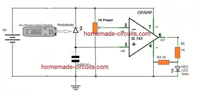
The remote control tester above using an opamp also looks pretty straightforward.
An ordinary opamp 741 is employed here for the detection. It is configured as a comparator. Its inverting input pin#2 is used as a reference level, and is set by fixing the connected preset.
The photodiode can be seen connected across the the non-inverting pin#3 and the positive line.
The preset is adjusted such that in normal condition when no signal is being received by the photodiode, the LED at pin#6 stays just shut off.
This is actually very easy, just switch ON power and begin adjusting the preset to-and-fro, and set it at a point where the LED just remains shut-off.
Next, point a TV remote control handset towards the photodiode, press any of the buttons of the remote control, you will instantly find the LED blinking in response to the remote control's coded IR signals.
Using TSOP1738 IC
The TSOP17XX series infrared sensors are specially designed for IR remote control operations. Even our TV sets use this versatile and efficient device for sensing and decoding IR signals and for executing the necessary commands.
A simple remote IR tester can be built using the same IC, through the following schematic:
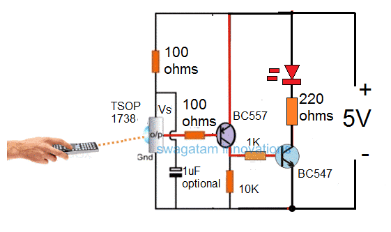
Again the remote tester design using a TSOP1738 appears extremely straightforward.
The connection arrangement of the TSOP IC is in its standard form, rest of the circuit is as simple as it can be. Just a couple of transistors are enough to get the circuit working in the most versatile way.
The great feature of this circuit is its immunity to noise and ambient light, not forgetting the sensitivity and range too. The detection range is actually awesome, you can point the remote handset to an opposite wall and still get the LED to respond efficiently from the reflected IR rays.
The aim of the above explained remote tester circuits is to show how a simple IR circuit can be used for activating an LED in response to IR rays from any ordinary IR remote control system.
The LED can be easily replaced with a relay for accomplishing more complex jobs as per a given application requirement, or as per user preference.
Have questions? You can put them forth as comments below, all your queries will be addressed ASAP.
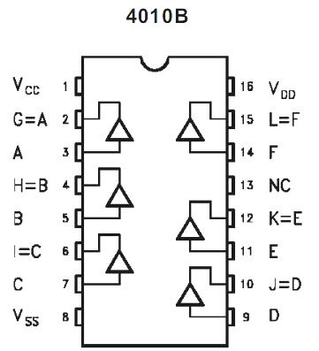
Using CMOS Gate
The IR tester circuit is demonstrated in figure below. IR phototransistor Q1 gets the transmission signal through a remote control handset and directs it to a single buffer gate from the CMOS IC 4010 which is a non-inverting hex buffer agte.
The gate output is used for driving an LED which flashes the received signal to enable the user to understand regarding the working of the remote control and that it is emitting a genuine IR signal. The finished remote control tester prototype could be mounted inside any appropriate enclosure.
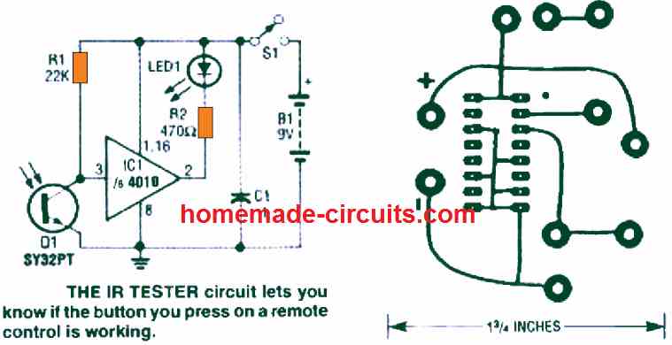
You must mount the IR phototransistor in a position where it may quickly be able to detect the IR signal, and the LED should be mounted in a place where it's easily visible.
A 9 -volt battery can be used for powering the circuit, nevertheless it is possible to replace the battery power with an AC powered supply if it is felt necessary.
After the unit is built, the tester can detect whether your IR remote control is having any sort of technical problem or not.
You just have to focus the remote control towards the IR phototransistor, and start pressing each of the buttons. The LED will begin flashing if the remote signal is in a proper working order.
IR (Infrared) Detector Circuit using IC 555
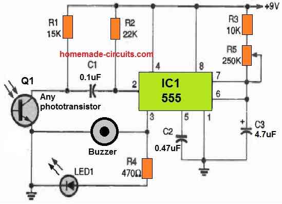
It provides both a sound and a visual output and extends the captured pulse's on time to create the output more noticeable.
When a remote's IR output pulse is detected, phototransistor Q1 delivers a negative-going pulse to the trigger input (pin 2) of the 555 IC1.
The settings of C3, R3, and R5 control the timing of the output (pin 3) of the 555 in a one-shot timer circuit.
Pin 3 swings high in response to an input pulse detection, turning on LED1 and turning on the piezo buzzer, BZ1.
R5 should be adjusted to its highest resistance value for extended output pulses. Increase the value of C3 to extend the circuit's on-time range, and decrease the value of C3 to reduce the on-time range.


Questions & Answers
Mr. Swagatam,
Again, I will do my best to explain the items that you do not fully understand.
#1) There is no discrimination in the amount or type of currency dropped through the slot. It is strictly a matter of conscience. Therefore,, when I referred to someone dropping a $5 bill, it was meant only as aa point that one would light more candles than one who dropped a quarter (25¢) through the slot. In truth of fact, there are 2 other displays which have a separate ‘drop box’, which is NOT electrically connected to their associated displays. It’s strictly a personal honour system. It’s strictly a free-will offering.
#2) I feel that you will have a complete understanding now. Your following comments are at the crux of my problem …. the money-detecting / IR circuit. Regarding the 1N914 diodes ….. yes!, I surmised that they are there for some sort of ‘feedback’ signal, or keep-alive, but I could not determine how they actually provided this. So, this was one question that I had.
it seemed very strange because essentially this is a very simple circuit overall, and it seems to have blossomed into something far more intense.
As I mentioned in an earlier post, the reason that the money detecting circuit seems to be most challenging is because when I was tasked with delving into the problems (last year sometime), it was because there was an attempt to vandalize these displays, physically breaking into the locked compartment where the money collects. In the process of this vandalism, the IR circuit was partially destroyed. However, I was able to reconstruct it physically, but not electrically because the fine wire leads were sheared off at the point where they entered the encapsulation. Example: Think of a typical epoxy-encapsulated small signal transistor (2N3904), where one of the EBC wires is sheared at the point it escapes the epoxy body. That’s what I was faced with. On one side of the slot, the two devices were connected in series, each device having only 2 wire leads. I assumed that these were 2 IR LEDs, aimed at the IR photo-transistors directly opposite. The reason I am convinced that the opposing IR devices are transistors and NOT IR receiver LEDs, is because there is 3 wires in this side of the circuiit. On the other side, there is a small gauge red wire, connected to a terminal, the other terminal has a short wire going to the 2nd device, and the other terminal (lead) is connected to a small gauge black wire. When did my tracing, it was evident that the red wire went to the +V supply, the black wire to the -V )ground, common) side. This is why I was convinced that these devices were IR emitter LEDS. On the opposite side, the two components had 3 wires: red, black, yellow. As best I could recreate the circuit, using glue to keep the wires properly positioned, the red & black wires went to corresponding leads of these components; the yellow wire went to the 3rd lead of these components. Logically, I concluded that these components were IR (receiver) NPN transistors. Finally, as I previously mentioned, I bought a selection of IR emitter LEDS, receiver LEDs, & some IR transistors, but I could never et any combination to work properly …. even just supplying a signal to a red or green std. LED, NOT even considering the candle circuit. This became the main frustration for me.
And, quite frankly, I don’t understand why, since I’ve seen numerous posts, both in the PINTERST site and the YouTube, where contributors have described simple circuits showing how to use IR devices to detect the presence or absence of an object through a specified pathway.
Finally, when I came upon the TSOP & TSAL devices, I became more confused, and that’s what led me to solicit assistance from you.
AGAIN!!!!, I must THANK YOU for all your efforts in understanding this project.
karl t.
Thank You again Karl, for your in-depth explanation,
Ok, so let’s first focus on the IR coin obstruction detector circuit and try to sort it out first.
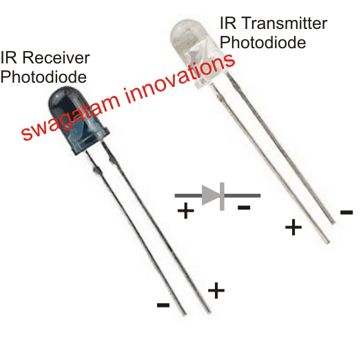
For any obstacle detection application, we have dedicated IR diode pair which is normally used for this purpose:
As indicated in the above figure one diode is supposed to work like a transmitter and the other one as a corresponding receiver device.
If the above are configured correctly, then the obstacle detection should work correctly.
Alternatively, we can also use a simple LED/LDR combination for implementing the obstacle detection, which is completely hassle free and does not require any critical circuitry.
Another simple idea is to go for a ready-made opto-interruptor module which is preconfigured and you can directly configure your 555 monostable with its output pinouts:
You can search for “opto-interruptor” online to get a clear idea regrading its structure and its working principle.
Let me know your opinion n this.
Hello Mr. Swagatam,
I’ll reply to your latest questions in order. Please keep in mind that I have no formal schemaitcs for this display, so I can only surmise certain facts about its overall theory of operation. What I have been able to glean from some research is that it was originally assembled by a family-owned furniture-style woodworking company in So. Florida about 40 years ago. Evidently, this company has ceased to exist.
Furthermore, the electronics controlling the candles seems to be very rudimentary. The power supply, for example, is an ACOPIAN, multiple output switching-type unit …. far overkill for the intended purpose.
Secondly, the p.c. board used for both the 555 circuit AND the 556 circuit is the SAME layout. To accommodate the 555 circuit, traces are cut & bridged with bare buss wire. This also applies to the 556 circuitung, which leads me to believe that this part of the display was done by an amateur, a hobbyist in electronics, and NOT by a professional company making these displays for a product line. Now, to reply to your questions:
#1) How do the29 candles react? When someone inserts money into the slot, NOTHING actually happens, UNLESS that person presses a pushbutton switch on the top of the ‘candle’. Then the light inside that candle begins to flicker.
#2) No. none of the individual candles lights until the pushbutton is pressed. Then, and only then will that candle begin to flicker. And, as I’ve explained previously, I believe the reason for the 556 timer is twofold. On one hand, it controls the flicker of the bulb; on the other hand, once the flickering begins, it also initiates the 2nd timer so that the flicker time extinguishes after a certain time period … let’s say 15 minutes.
#3) Only the one candle that was pressed after the time period elapses (as I explained in #2). IF someone comes along after a while, and drops money into the slot, any & all existing flickering candles are NOT affected, BUT the second person now can ‘light’ a new candle. And, by the way, this is all on the honor system, so IF someone drops a $5 bill into the slot, and decided to light 5 candles, they can do so.
Your #3 question touches on the primary reason for the main 555 timer in my opinion. I believe that its fundamental purpose is to control (limit) the ability to press multiple candle buttons over a long period of time. In other words, setting it for approx. 15-minute duration, allows the person to dwell on their meditation, light as many candles as they deem fit, then leave. In the interim, this main timer (555) will expire, so when the next person comes, they must insert money to reset or reactivate the circuit, allowing for additional candles to be lit.
As I also explained, after reverse engineering the entire circuit, and breadboarding it on a vector board,
I tried to duplicate the action as best I could, but my stumbling block was in getting the initial circuit of the money through the slot to trigger the main 555. I could trigger it with no problem by forcing the trigger pin on the IC, but I could not get it triggered by using various combinations of IR LEDs, transistors, etc.
Also, there was one unknown to me. Since the main 555 board suffered a catastrophic failure where the TIP transistor was located ( a direct short causing a resistor to disintegrate), I could only guess at the value. Since it was in the emitter to ground, I assumed it was a low ohmic value, but I still can’t justify its worth. In my breadboard, I put the emitter to the ground rail; saw no change in operation.
Finally, I still don’t understand the function of the 1N914 diode, but it is on each of the candle circuit boards, going to it’s own card-edge connecto circuit, and paralleled back to the 555 timer board. This is what led me to believe that it’s function is some sort of ‘keep alive’ signal.
SIR!, IF I wasted too much of your time, I understand, so don’t feel obligated. I fully understand your deep love for electronics, and helping people, which is quite admirable in our modern society, but I feel somewhat embarrassed that I can’t solve this problem on my own, given my many decades in circuit design / programming.
THANK YOU!!!
karl t.
Thank you very much Karl, for your consistent effort to explain the actual working of the design.
The functioning of the system is quite clear now.
However your following spec indeed looks very difficult to implement practically.
…”IF someone drops a $5 bill into the slot, and decided to light 5 candles, they can do so”
That means the number of candles a person can turn ON will depend on the amount of money he puts into the slot?
How can the electronic system recognize or detect how much money was inserted?
And as you say you have already reverse engineered the whole system, so my question is were you able to make the 556 candle stages work correctly? If yes, then the IR based money detection stage can be fixed easily, no issues about that.
But again, detecting how much money was inserted into the slot remains a big challenge, and i have no idea how to solve that.
The 1n914 diode seems to be some kind of feedback from the individual candles to the main 555 monostable, currently I cannot figure out the main purpose of these diodes. We can get to it once the working of all the interconnected stages are fixed.
Let me know your opinion on this?
Hello Mr. Swagatam,
THANK YOU VERY MUCH. I know that you are in India. IF you were more local (u.S.A.), I would make a copy of the schematic, mail it to you.
As I previously mentioned, there are 3 rows of ‘candles’, about 29 total. The individual candles
have a pushbutton switch at the top, which, when pressed, lights the one candle. The ‘light’ comes
from a miniature base (screw-in) incandescent bulb to render an orangy-glow through the semi-translucent candle shell. These p.c. boards plug into a std. .156″ pitch, 6-circuit card-edge connector. All #1 pins are parallel-connected, etc. Two pins are for the 15v D.C. supply, two pins for
the pushbutton switch & two pins are for the control signals.
Here’s how it’s supposed to work to the best of my diagnosis. The main 555 timer gets triggered by
the falling of the money through the slot. From my calculation, it seems to have an active timer period
of about 20 minutes + or -. Coupled to pin 3 of this 555 is a (NPN) TIPxxx transistor, the output of which goes onto one of the signal lines. The circuit inside each candle, consisting of the 556 IC has
the dual function of providing the square wave output to make the bulb flicker. Therefore the ON time / OFF time is very unbalanced. The 2nd half of the 556 is a duration timer,set for some time period, let’s say 15 minutes. So, after 15 minutes, this particular candle will stop flickering.
What I don’t understand is the return line. which is diode-isolated (1N914) on each candle circuit. This is the other common line connected to the card-edge connectors, with it going back to the 555 timer board.
Because I had no manufacturer’s schematics, as I mentioned, I reverse-enfineered the circuits,
carefully shining a bright flashlight through the p.c. board to ensure that I got the circuit drawn
correctly. Then, I duplicated the two circuits on a prototyping board, with all the exact same value
components, which were easily identified & measured. The ONLY area of problem was with the
IR detectors since there were no discernable numbers on them … only one of the 4 components
had a ‘number’, and it seemed like it was a date code. There were parts of numbers on one of the
other components, but when I did a seatch nothing appropriate resulted. And, this is the crux of my
original situation ….. trying to replace these unknown components with modern IR transmitter / receiver parts.
By the way, when I did my breadboarding, I used a 12v (regulated) D.C. power supply because I didn’t have a 15v supply. The miniature bulb was much dimmer, as would be expected. Therefore it’s evident that to yield the same result, the circuit would have to be powered by the same 15v supply.
The ONLY rationalization I can think of for the return signal line from the candles to the 555 main
timer is some sort of a ‘keep alive’ signal. In other words, just as long as ANY candle is still flickering, the main timer is also kept in its output state. So, IF no candles are flickering, then the main timer would reset UNTIL a person dropped money into the slot, which begins the cycle once again.
Finally, don’t forget the fact that during my initial investigation, I saw date codes on the ICs which
date back to the ’80s. Therefore, this design, using 555 timers is very simplistic. Surely, IF it were
to be conceived in our modern era, I’m sure a microcontroller (ARDUINO, etc) would be used instead, since a properly designed program would handle all the operational functions with ease.
Whatever circuit you devise, don’t forget …. the ‘flickering boards have to plug into a std. 6-pole
card edge connector.
AGAIN …… i say THANK YOU for your interest in this project.
karl t.
.
You are most welcome Karl,
I understand the basic functioning of your applications, however I am still not sure about the following things:
1) How do the 29 candles react and respond to the 555 monostable switch ON when a coin is dropped and detected?
2) Why are the manual pushbuttons given to activate the candles, because as per my assumption the candles are supposed to illuminate in response the coin detection?
3) When the flickering stops, do the candles also shut off completely?
We can diagnose the presence of feedback links once I know the complete step-by-step working of your circuit.
Please let me know your opinion on this?
Mr. Swagatam,
I truly appreciate your patience & willingness to be involved with this project. The complete ‘display
consists of 3 rows of ‘candles’ that people can light. It is a devotional display. From the date codes on some of the ICs, it was first built in the 1980s. Some of the 556 timers have the Signetics trademark, so that shows how old it is, since Signetics was the originator of the 555 timer IC. Atop each ‘candle, there is a pushbutton switch to activate the individual unit. The reason for the 556 in each unit is that one half controls the flickering of the light bulb, while the other controls the length of time that this one ‘candle’ stays lit.
The problem originated (for me to get involved) was after damage was done to the money slot. The IR sensors were destroyed, and a coin somehow got wedged under the main (555) circuit board, causing a short, burning up a 1/2w resistor connected to the emitter of a TIP120 transistor.
Each ‘candle’ has a plug-in p.c. board with the 556 mounted & the associated passive components.
I have schematics (that i reverse-engineered, but they were created in an old release of EAGLE.
The reason I think that the main timer (555) is being reset to keep active, is because on each of the
556 circuits, there is a 1Nn914 that is connected to one of the connector tabs of the card edge connector, and this line goes back to the main 555 circuit board.
IF there’s a way that I can attach the schematic files, so you get a better understanding, please let me know how to do that. I thought about making a significant circuit design change by incorporating a
PARALLAX STAMP2 as a controller. I have several BS2P microcontrollers from old projects and a few of the larger ones, the BS2P40, with the associated Carrier boards, and I have the PARALLAX STAMP editor on several PCs, so I could write a BASIC program, but that’s a bit involved, and IF I could just get the IR sensors to function properly, it would be less of a task.
Again, THANK YOU for your interest in this project.
karl t.
Thanks Karl,
Yes I am definitely willing to help you figure out this circuit.
However, going through an external schematic can take a lot of time and effort, which can be difficult for me at the moment.
Instead, if you wish I can help you to build the entire circuit from the scratch, stage wise.
You just have to tell me the operations of the various stages in a step wise manner, i will try to design it for you and help you until you succeed.
Let me me know if you find this idea good.
Hello Mr. Swagatam,
I’ve seen many examples of circuits for IR detectors,
both in your blog, and elsewhere. I’ve assembled some of
these circuits, but don’t seem to get the results that I should.
I have a simple project: I have an alum. plate with a slot in
it. The slot is approx. 2.5″ long x 0.3″ wide. The purpose of
this slot is for dropping money (coins or paper) into a collection
bucket. The act of dropping the money is to break the path
of the IR transmitter / receiver components fastened to the
underside of the plate. On each side, there are two transmitter
LEDs, opposed by 2 receiver (IR) NPN transistors in series
with each other. The output goes to trigger a 555 timer,
which then controls other circuitry.
My questions are twofold: (1) Why do I never see a specific
part number for the IR LED, regardless of the sources of the
circuit schematics & associated parts list. They are always
referred to just as IR LED? Yet, when I go to various elec. components
suppliers (DIGI-KEY, MOUSER, NEWARK, etal.) I see numerous
IR LEDs available for sale?
(2) I noticed that many IR circuit designs use VISHAY TSOPxxxx,
and TSALxxxx components, but these seem to be usable ONLY
if one pulses them with an oscillator circuit (555 type)?
Can you comment on my questions? Can you suggest a better
circuit to detect the dropping of money through the slot to activate
the primary timer?
Thank you.
k.t.
(in U.S.A.)
Hello Karl,
There are basically two types of IR sensors, one are in the form of photodiodes or phototransistors, and others are in the form of ICs such as TSOP1731 or PIR:
https://www.homemade-circuits.com/tsop1730-33-36-367-38-40-56-infrared/
The photodiode LEDs and the phototransistors can work without any special frequency and therefore may get triggered even by direct sunlight.
The above components are mostly similar with their characteristics and therefore universal, and do not need a specific part number to fit in a particular circuit.
The TSOP17XX require a frequency to toggle them, for example the TSOP1738 IC requires 38 kHz frequency to switch ON, and therefore they are precise with their operations, and cannot be triggered by sunlight or any stary IR.
PIR sensor different, they are designed to sense only the IR radiation from the bodies of living beings such as humans and animals.
In your application any photodiode pair (transmitter/receiver) will work perfectly and produce the intended results, if they are configured correctly.
I can definitely suggest a better circuit for you…
Please let me know if you any further doubts or questions.
OK!, Mr. Swagatam,
Since you offered, I accept a better solution for this project. Here’s the rest of the project, just so you have a clearer understanding. When the money is dropped through the slot, it triggers a monostable 555 set for roughly 1/2 hr. The ‘start’ signal from this 555
starts a ‘556’ dual timer circuit, which causes a ligh-flickering effect for a certain period. There are multiple ‘556’ circuits in this display cabinet. If no additional money is deposited,
after the time period, the flickering lights will go out, BUT if additional money is dropped,
then the signal will be maintained. However, individual lights will extinguish based on the
time constant of the one section of the ‘556’.
Thank you for your detailed explanation, however there are still some doubts.
The additional money cannot be detected until the 1/2 hours is lapsed, because a normal 555 monostable will not respond to additional triggers once its monostable action is activated.
Also, what is the purpose of using multiple 556? Is it only to generate random flickering effects at different flashing rates, or is their any other specific reasons?
How many monostables are used in this circuit and how many astables?
Mr. Swagatam,
YES!, I understand that about the 555 in monstable mode. One of the ‘problems’ with this display is that there are no schematics for the circuits, so when I was approached to work on it, I had to carefully retrace the crude p.c. boards to derive the existing circuits. To go back even further, as to why I got involved was because where this display was located, it was vandalized. The original IR sensors, located on the underside of the alum. plate evidently were originally a paired unit, similar to the popular OMRON sensors that one sees used as a tachometer for motor. I think
initially they were cut apart, then the individual components were literally glued to the
plate, and small gauge wires used to connect these. On the ‘transmit side, the LEDs were connected in series; on the ‘receive’ side, they were also connected in series, and the output connected to the pin on the trigger 555. Each of the p.c. boards with the 556 timers, has a 1N914 diode, on a common bus line going back to the 555.
After I did my best due diligence to reverse engineer the circuit and look at it on paper, I duplicatd it on a prototype board, but since I didn’t have any OMRON-type sensors to cut into pieces, I sourced some individual IR components, and this is where I ran into the trouble. So, knowing of your willingness AND experience in electronic circuitry, I decided to solicit some suggestions from you, most especially to get advice on the IR components, which I’ve never used in any previous projects.
Again … THANK YOU for your interest in this project.
By the way, the D.C. power supply for this circuit is a multiple output switcher, but only the 15v output is being used. In my duplicate version, I have only a 12v power supply, which works, but the incandescent bulbs used to not flicker with the same
luminosity ….. NOT unexpected, but it does prove that the original designer fully meant to take advantage of this higher voltage source, coming very close to the absolute max. ratings for the 555 / 556 ICs.
Thank you Karl,
I appreciate your detailed explanation.
However, my previous questions are still not solved.
Retriggering the monostable until the previous interval has elapsed, may not be feasible.
And why do we need multiple 556 ICs for the LEDs?
Alternatively, you can explain your basic requirement, I will try to figure it out.
Hello,
So when I made the circuit with 2 transistors, it only worked when I wired the Photodiode in forward bias, which I know is not what the schematic shows. why could this be?
Hello, that sounds strange, because the photodiode must be connected in the reverse bias direction for it to work….you can see that in the video.
Hi, i wanna theIR Remote Control Decoder circuit without Arduino. That show me Button Hex Code & IR Protocol (NEC & etc)
Help me please.
Hi,
You can refer to the following post:
https://www.homemade-circuits.com/simple-100-meter-rf-module-remote/
Hello Swagatam!
A want your help for make the simple shematic of sensor carbone monoxyde With transistor and module MQ-7 withowt arduino. Tanks
Sincerly, MAHMOUDI Ahmed
Hello Mahmoudi, I do not have the exact circuit that you want, but you can try referring to the following circuit, which is related to your question:
https://www.homemade-circuits.com/simple-alcohol-detector-meter-circuit-using-mq-3-sensor-module/
Hello good afternoon. Thank you for your quick response.
I actually need an RF circuit to use as security for my car. For example an RF transmitter and receiver… The receiver will be installed in the car and I use the transmitter… And when I get closer the receiver is activated and when I move away it is deactivated… For example a relay.
Thank you so much.
Hello Carlos, I do not have an RF based circuit, I have a GSM based circuit which you can find in the following link. RF circuit can be also designed but it can be easily hacked by anybody, because RF waves are not foolproof.
https://www.homemade-circuits.com/gsm-car-ignition-and-central-lock-using/
Hello sir Swagatam good afternoon, can you help me please? I looking for an electronic circuit. For example I need IR signal to control a relay but It should only work with the frequency of your emitter.
Hello Carlos,
you can try the following concepts:
https://www.homemade-circuits.com/infrared-controlled-car-door-lock/
https://www.homemade-circuits.com/remote-controlled-fish-feeder-circuit/
Hi. Great educational article. I enjoyed reading it.
Of course, the easiesty way to test infra-red remotes is using a digital camera, or better, any mobile phone that can take pictures.
Set the phone up ready to take a picture, point the remote at the “camera” and press any button on the remote.
The transmitting LED on the remote will appear as a purple-ish light.
This has saved me quite a lot, looking after all kinds of devices in my career, and now in y retired role as that electronics nerd.
But the article is still well worth reading for the educational value.
Thanks for posting.
Hi, Glad you liked the post, and thanks for explaining the easy alternative way of testing an IR remote.
Now want happens if I connect 1k or 10k potentiometer whether I get correct output or not
Please see the article, I have explained how to adjust the preset.
What is potentiometer range used in op amp ciruit
Any value between 1K and 10K will work…actually it’s a preset or a trimmer, not a potentiometer as incorrectly shown in the diagram