The articles explains a digital thermometer circuit project that works without a battery. Instead of a battery the circuit utilizes a small solar cell and operates by deriving power from the ambient light available from the surrounding light sources.
This allows the circuit to be extremely compact, light weight, versatile and hassle free while measuring temperatures from a given source.
The thermometer can be used for measuring temperature of a human body, temperature of a room, heatsink, for weather analysis, or any other suitable application which requires critical temperature measurements between 0 degree and 100 degree Celsius.
Basic Working concept
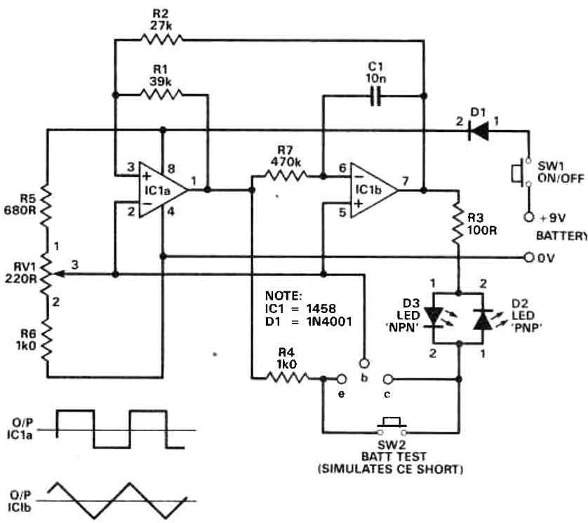
Referring to the circuit diagram below, IC1 works like a temperature sensor device. This IC is a popular LM35 chip which produce a linearly increasing DC output in response to a proportionately increasing ambient temperature around it. To be precise it generates an output DC at a rate of 10 mV per degree Celsius rise in its case temperature.
The LM35 has an in-built calibrated circuitry, which enable to produce 0 V at 0 °C.
Apart from this IC, the other main element of this light powered thermometer is the integrated circuit ICL7136 (ICI) which internally is made up of a digital voltmeter stage, a decimal shifter and an LCD output interface which operates a 3 and 1/2 digit LCD panel for the temperature readout.
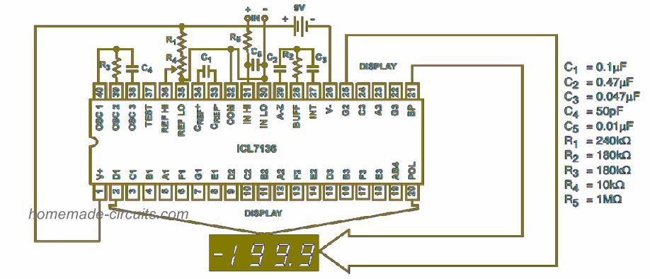
This IC also has an internal oscillator which works with a minimal clock frequency which ensures that the the entire module is able to function using minimum power, yet without any flicker on the display.
The temperature readout calibration of the circuit is carried by adjusting the preset P1 appropriately.
How the Circuit Works
Diode D1, and resistor R11 ensure that the LM35 turns negative voltage in response to an ambient lower than 0 °C.
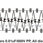
The LEDs D1, and D2 here do not function as normal indicator LEDs rather as a reference voltage generators for getting a reasonably accurate 1.6 V constant reference, which require only as low as a few uAmps for this functionality. Although standard zener diodes are more accurate with their reference potential, zener diodes require much higher forward current compared to LEDs, and therefore zeners have been avoided for this application.
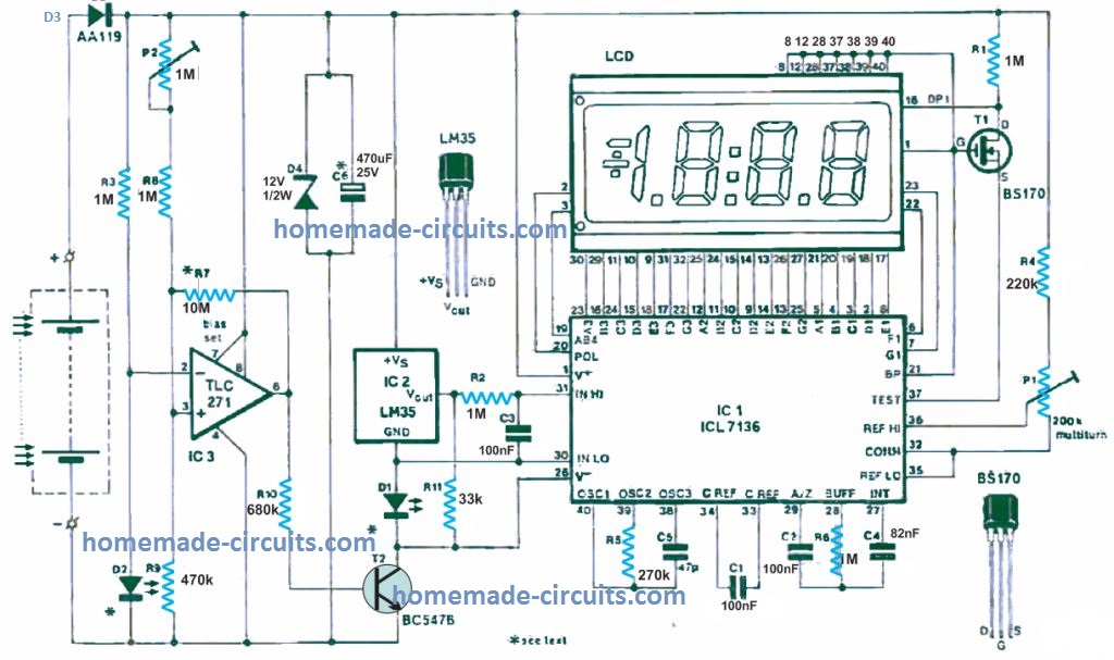
The IC3 along with this associated components work like a voltage monitor stage for the solar cell supply.
The op amp switches OFF the main thermometer circuit stage through the transistor T2 whenever the solar cell output voltage drops below 0.7 V.
This feature makes sure that the IC1, IC2 stages do not malfunction during such low voltage and produce temperature readouts with errors.
In order to work correctly the LM35 requires a minimum supply voltage of 5.5 V, while for IC2 the minimum reference potential required is 7 V for its normal functioning.
Working with Low Ambient Light
Op amp IC3 is rigged as a Schmitt -trigger such that it works with a hysteresis level of 1V. Meaning, the IC output will switch ON when the solar cell voltage is 8 V, and switch OFF when it drops below 7 V.
The 7 V switch ON threshold is precisely adjusted using the preset P2.
The circuit comprising IC1, IC2 is able to work normally within a current range of 10 to 200 micro amps. When light source on the solar cell is insufficient, and its current drops, the IC3 switches OFF power to IC1/IC2, which removes loading on the solar cell and its voltage rise to 8 V. This 8 V gets stored in the capacitor C6. IC3 detects this and switches ON power to the circuit so that the thermometer now works using this stored energy. When C6 discharges below the 7 V threshold, IC3 yet again cuts off power to the circuit through T2.
The above functioning of IC3 is actually very useful in situations when the ambient light is low or drops to a level where the solar cell is unable to generate sufficient power for the thermometer for its normal functioning. In such conditions, the IC3 toggles the power from the solar cell ON/OFF such that the user is able to check the temperature in a switched ON/OFF mode, but definitely without an error. This allows the thermometer to keep working perfectly even in low ambient light conditions, instead of completely shutting down.
The hysteresis level (1 V) can be changed according to user preference by changing the value of the resistor R7
The capacitor C6 value determine how fast the ON/OFF happens for IC3/T2 in low light conditions. Decreasing C6 value will cause faster ON/OFF of the display and vice versa.
Construction and Setting up
The PB design for the light powered thermometer can be visualized in the following image.
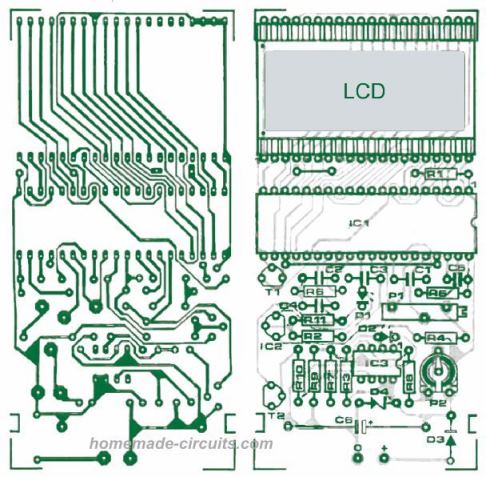
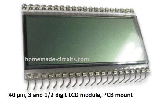
Assembling the PCB is easy, but the LCD module must be handled with precautions while inserting into the PCB, since the device is quite delicate and vulnerable to breaking.
Make sure you do not forget the A couple of wire connections on the PCB. Do not initially fit IC2 LM35 on the PCB to allow the introduction of +1.000 V across Vout and GND terminals of the LM35. Before this make sure to adjust P1 so that the display reads 100 °C. Once this is done, remove the solar cell or the external supply if any used, and now fix IC2 on the PCB.
Solar Cell
The solar cell can be any mini or micro solar cell combined to produce 9 V, at 10 mA.
If you do not wish to use a solar cell or light power, rather a normal battery, you can replace the power source with an ordinary 9 V PP3 battery which would probably last for ages due to extreme low consumption of the design.
WARNING: The proposed light powered digital thermometer shouldn't be used as a clinical thermometer, unless the circuit is verified and confirmed from an authorized laboratory.
Need Help? Please Leave a Comment! We value your input—Kindly keep it relevant to the above topic!