Here a simplest yet quite accurate inductance meter is presented, which can be built within few minutes. Furthermore, the circuit can be powered-up with a single 1.5V cell. However, a frequency meter would be required to work-out the inductance.
Designed and Presented by: Abu-Hafss
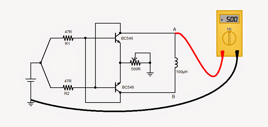
Using Cross-Coupled NPN BJTs
The circuit is pretty straight forward wherein, two NPN transistors are cross-coupled to form a flip-flop oscillator. The values of R1 and R2 could be anything between 47 - 100R. The frequency of the oscillation is inversely proportional to the inductance and it can be calculated with the following formula:
Frequency (kHz) = 50 / Inductance (uH)
CALIBRATION:
Initially the circuit has to be calibrated using a known inductor, as described below:
Suppose, we have an inductor of 100uH. Putting the value of inductor (100uH) in the above formula, we get 500kHz.
Connect the frequency meter at point A or B and ground.
Adjust the POT until the meter reads 500kHz. Now the circuit is calibrated.
INDUCTANCE MEASUREMENT:
Connect an unknown inductor across A & B.
Power on the circuit and read the frequency at point A or B.
The above formula can also be written as:
Inductance (uH) = 50 / Frequency (kHz)
Putting the value of frequency in this formula, the value of the inductor can be found.
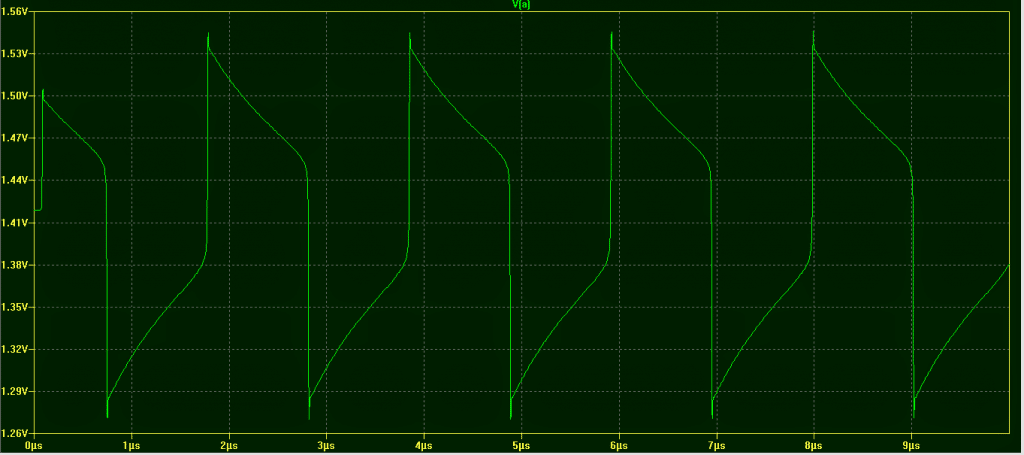
Waveform Image:

Questions & Answers
Hi, in the above formula do you mean 50,000 = 50 (fifty) because if it is fifty thousand then the formula gives result 500 MHz not kHZ? 100uH=0.0001H.
You are right…it should 50 and not 50000, thanks for the correction, much appreciated.
Hi Swagatam, I appreciate very much your work and thanks for the feed back!
You are most welcome Emil!
Good day swagatam. Can the above circuit be use to get the value of ferrite core ( toroidal) inductors or is it for only air core inductors only. Thanks
Very good simple circuit, there are some useful ones like more complicated methods, which require a function generator and an osciloscope.
And even smaller inductances, even 1-2uH, can be measured well if we connect them in series with a larger one, for example a 33uH inductance. And we subtract the value of the larger inductance from the result.
Thanks for your valuable feedback…
Hi Emmanuel, You cam measure all types of inductors with the above meter, there are no such restrictions.
I built this circuit, it works okay for large inductances. It’s important to note though, that it won’t work for small ones, say < 5uH. I wanted to measure 330nH, that would be 150MHz, but the output doesn't go beyond 10MHz. I clearly need a different design for these.
Thank you for your valuable feedback!
Hi there, really great forum this thanks for your efforts! I am not very experienced with circuitry and am struggling with how to wire the pot into the circuit… should I have it wired with +volts on pin one, the line that ties gates one and one together to centre pin and ground to pin 3?
Thanks!
Hi, there are 3 pins in a pot. You will have to join the center pin with one of the outer pins and connect this to ground, and then connect the other free pin of the pot with the emitter pins of the transistor.
Can we use ordinary multimeter to measure the frequency
yes that’s possible…
How can we use ordinary multimeter to measure the frequency
by attaching it to one of these circuits
https://www.homemade-circuits.com/simple-frequency-meter-circuits-analogue-designs/
or buy a multimeter having the frequency measuring feature
Hi a question, how did you get the 50000 constant figure in the frequency calculation? Is that a bc546 characteristic? What if I use another npn such as n2222 or others? Does that constant change?
Thanks!
Hi, I am not very sure since it was not written by me.
However for a square wave frequency the standard formula seems to be like this IL = Api / 16fL
where IL is the current through the inductor, A is the RMS amplitude of the square wave frequency, pi= 22/7, and f is the applied frequency
you can use any similar small signal transistor, it is definitely not critical…2N2222 will work without any issues.
Thanks!
Hi Robin
Please note that each time the circuit is powered on, it does need to be calibrated. Otherwise, we might get variation in readings.
Hi Vishal Sutar
1. Yes.
2. Yes.
3. Please take note of my post of Nov. 5, 2014.
Hi Abu Hafss,
Its a simplest one…thanks for sharing.
I have some question
1. Does the calibration depends on cell voltage.
2. If so then can i give a fixed 5v supply to this circuit.
Hi Robin
Here is the waveform of the oscillation
The frequency of oscillation depends on the L/R time constant comprising the inductor and resistors R1 and R2. The time the waveform takes to change its state is directly proportional to the inductance. In the waveform we see, the time taken for one complete cycle is 2µs for a 100µH inductor.
In other words, inductance (100µH) = Time period (2µs) x 50 ……….(A)
And we know, Frequency = 1 / Time Period OR Time Period = 1 / Frequency
So replacing Time Period in Formula (A), we get
Inductance (µH)
= 50 x (1 / Frequency) OR
= 50 / Frequency (Hz) OR
= 50 x 1000 / Frequency (Hz) x 1000 OR
= 50,000 / Frequency (kHz)
Please note, that this circuit is quite sensitive to the supply voltage and it is fairly good to about 10µH.
It is good idea to a have a known value inductor say 100µH fixed in the circuit for calibration purpose. That calibration inductor and the inductor under test may be toggled using a SPDT switch.
How do you get the constant of 50?
Thanks for testing the circuits!
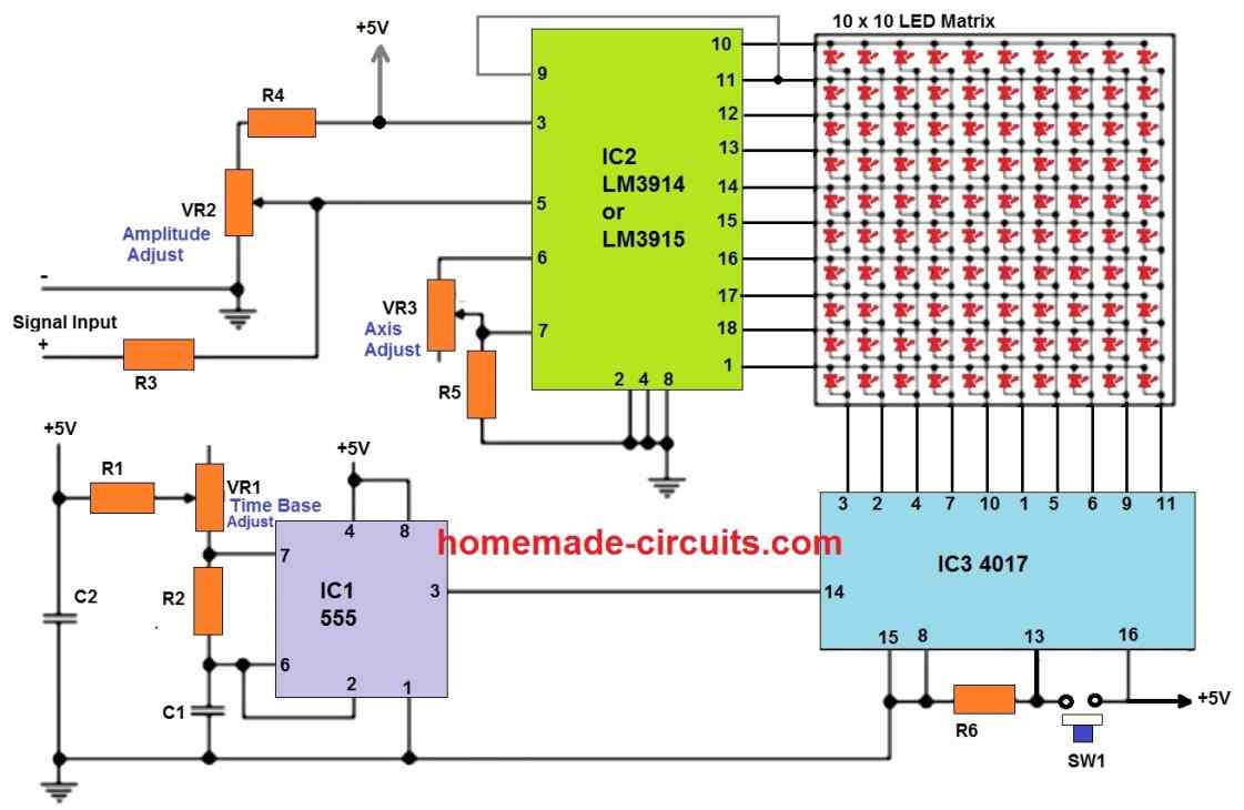
The 555 based design will need different sets of "C" for producing the corresponding sets of measuring range, however the design will not give accurate results with lower capacitance and may show vibrating or oscillating meter needle.
Hi Swagatum
I now understand it fully,I built the circuit and calibrated it and tested 3 other known inductance's ie:47uH and got 53.5uH,4.7mH and got 5.9mH,3.9mH and got 4.9mH.
Those figures will give me a good idea of what I've wound.
I also built the other circuit with the 100uA meter which may give more accurate results?But have no idea on how to fault find it and split it into smaller sections so as to check that you are on the right track
Just getting the above results from that tiny little circuit was a big boost for me
Thanks Robin
Hi Abu Hafss
This looks so simple its to good to be true,I'm going to try it.
Where did you derive that formulae from.
Regards Robin