In many critical circuit applications, like power amplifiers, inverters, etc it becomes necessary to use matched transistor pairs having identical hFE gain. Not doing this possibly creates unpredictable output results, such as one transistor getting hotter than the other, or asymmetrical output conditions.
By: David Corbill
To eliminate this, matching transistor pairs with their Vbe and hFE specs becomes an important aspect for typical applications.
The circuit idea presented here can be used for comparing two individual BJTs, and thus find out exactly which two are perfectly matched in terms of their gain specifications.
Although this is normally done using digital multi-meters, a simple circuit such as the proposed transistors match tester can be a lot handier, due to come the following specific reasons.
- It provides a direct display whether the transistor or the BJT are accurately matched or not.
- No cumbersome multi-meters and wires are involved, so there's minimum hassle.
- Multi-Meters use battery power which at critical junctures tend to get exhausted, hampering the testing procedure.
- This simple circuit can be used for testing and matching transistors in mass production chains, without any hiccups or issues.
Circuit Concept
The discussed concept is a remarkable tool that capably chooses transistor pair from all sort of possibilities in a nick of time.
A pair of transistors will be “matched” if the voltage at the base/emitter and current amplification are identical.
The extent of precision may be from “vaguely same” to “exact” and can be tweaked as needed. We know that how very useful it is to have matching transistors for applications like differential amplifiers or thermistors.
Searching for similar transistors is a detesting and taxing job. Still, it has to be occasionally done because the paired transistors are frequently utilized in differential amplifiers especially when they are operated as thermistors.
Commonly, a whole lot of transistors are checked using a multimeter and their values are recorded until there is nothing left to inspect.
The LEDs will lit if there is a response from the transistor’s UBE and HFE.
The circuit does the heavy lifting as you just need to connect the transistor pairs and monitor for the lights.
In total, there are three LEDs; the first one lets you know if the BJT No.1 is more efficient than the BJT No.2, the second LED describes the opposite. The last LED acknowledges that the transistors are indeed an identical match.
How the Circuit Works
Although this looks a bit complicated, it follows a relatively direct rule. Figure 1 depicts a basic type of circuit for better clarity.
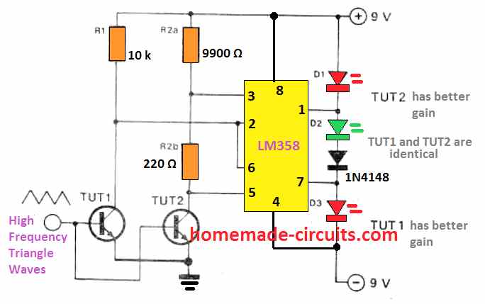
The Transistors Under Test (TUTs) are subjected to a triangular wave-shape. The discrepancies between their collector voltages are identified by a pair of comparators and indicated by the LEDs. That is the whole concept.
In practical terms, the two BJTs under test are powered by identical control voltages, as displayed in Figure 1.
However, we find that their collector resistance is fairly dissimilar. R2a and R2b are somewhat larger in resistance compared to R1, but R2a as a single unit has a smaller value than R1. This is the whole setup of the sampling circuit.
Let’s say the two transistors under test are exactly the same in terms of the UBE and HFE. The upward moving slope of the input voltage will turn both of them on simultaneously and consequently their collector voltages will fall.
Here, if the above situation is paused, we would observe that the second transistor’s collector voltage is a tad lower than the first transistor because the whole collector resistance is larger.
Because R2a has a lower resistance than R1, the potential at the junction of R2a/R2b will be marginally larger as opposed to the collector of transistor 1.
So, the “+” input of comparator 1 will be positively charged against its “-” input. That shows the output of K1 will be ON and LED D1 will not illuminate.
At the same time, the “+” input of K2 will be negatively charged against its “-” and due to that the output will be OFF and LED D3 will also remain shut off. When K1’s output is ON and K2 is OFF, D2 will be switched ON to show both transistors are exactly the same and are matched.
Let’s look if TUT1 has a smaller UBE and/or a larger HFE than TUT2. At the rising edge of the triangular signal, the collector voltage of TUT1 will fall quicker than the collector voltage of TUT2.
Then, comparator K1 will respond the same way and the “+” input will be positively charged against the “-” input, and consequently, its output will be high. Because the low collector voltage of TUT1 is linked to the “-” input of K2, it will be smaller than the “+” input which is attached to the collector of TUT2.
As a result, the output of K2 starts rising. Due to the two high outputs of comparators, D1 fails to illuminate.
Because D2 is linked like D1 and between two high levels, it will not be lit either. Both these conditions cause D3 to illuminate and thus conclude that the gain of TUT1 is superior to TUT2.
In the event TUT2 gain is identified as the better of the two transistors, this results in the collector voltage to drop more quickly.
Therefore, the voltages at the collector and the R2a/R2b junction will be smaller compared to the collector voltage of TUT1.
Conclusively, a low signal of the “+” inputs of the comparators will switch to low with respect to the “-” input allowing the two outputs to be low.
Due to that, LEDs, D2 and D3 will not light up, but only D1 will be illuminated at this point, which signals that TUT2 has a better gain than TUT1.
Circuit Diagram
The whole circuit schematic of the BJT pair tester is depicted in Figure 2. The components found in the circuit are an IC, type TL084 that houses four FET operational amplifiers (opamps).
The Schmitt trigger A1 and an integrator are constructed around A2 to develop a standard triangular wave generator.
As a result, an input voltage is supplied to the transistors under evaluation. Opamps A3 and A4 operate as comparators and their respective outputs are the ones that regulate the LEDs D1, D2 and D3.
When inspected further at the union of resistors in the collector pins of the two transistors, we understand the reason to use a less complex circuit to investigate the rule.
The ultimate schematic appears to be very complex, as a ganged dual pot (P1) was introduced to default the range where the transistor characteristics are believed to be exactly similar.
When P1 is turned to the extreme left, LED D3 will illuminate which means that the pair of TUTs will be the same with less than 1% difference.
The tolerance may deviate by around 10% for the “matched pair” when the pot is completely rotated in the clockwise direction.
The upper limit of the accuracy is depended on the values of the resistors R6 and R7, which is a result of counteracting the voltage of TL084 and the tracking precision of P1a and P1b.
Furthermore, the TUTs will respond to alterations in their temperature hence this must be observed.
For instance, if the transistor was handled by people before plugging it to the tester, the results are not 100% accurate due to temperature deviations. And so, it is recommended to delay the final reading until the transistor has cooled down.
Power Supply
A balanced power supply is necessary for the tester. Since the amplitude of the supply voltage is irrelevant, the circuit works fine with a ±9V, ±7V or even at ±12V. A simple pair of 9V batteries can supply power to the circuit because the current draw is as little as 25 mA.
Furthermore, this type of circuits is usually not operated for very long hours. One advantage of having a battery-powered circuit is that the construction is well-ordered and simple to work.
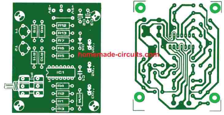
Printed Circuit Board
Figure 3 displays the tester circuit’s printed circuit board. Given its small size and very few components, construction of the circuit is pretty straightforward. All that is required are a standard IC, two transistor mounts for the TUTs, some resistors and three units of LEDs. It is important to ensure resistors R6 and R7 are the 1% types.


Questions & Answers
Need to buy a complete assembled pcb to match pair RF transistors i.e 2N5070
Sorry, nowadays i don’t sell assembled kits.
Can you recommend a circuit diagram
According to me the first design looks simple and effective.
I’m confused. Will the circuit in Figure 1 function as described in the article, or just the significantly different one in Figure 2, or both?
The first diagram is the shorter version of the second one, it is presented for ease of understanding
Thank you. But will the shorter version work? If so, what are the operational advantages to the second version? I have a LM358. I don’t have a TL084.
Actually I have not gone through the whole article so I am unable to suggest whether the first design can be used as effectively even with the absence of the pots. The second elaborate design has pots for some good reason. The article was submitted by an external author.
Can I buy a PCB for this device to solder, or design my self?
Thanks
IAs I have constructed a power amplifier I have used this circuit to match the transistor of the first stage of the amplifier which is a differential amplifier consisting of BC550C and BC560C. Testing the 550C(NPN) there was a great success. Testing the 560C (PNP) there was a big problem. No matching at all, although I have tested more than 100 transistors. Do you have any possible explanation? Is there a different lead connection when you test PNP?Thanks a lot
The above circuits are designed specifically for testing NPN BJTs not PNP BJTs. Inserting PNP will cause the circuit to malfunction.
for PNP, many modifications will need to be done, for example changing the op amp input polarity, collector/emitter polarity etc.
Thanks for your quick response. The elektor magazine back in 1983 doesn’t refer anything about NPN and PNP. They say that you can match any transistor!! Please check the article and notice that there is no word NPN or PNP on it. I was suspected that something is wrong because at the schematic there are 2 NPN transistors! It’s a big mistake of the elektor magazine not mentioning only NPN usage! Don’t you agree?? Thanks
Even if it is not mentioned, it is an understood fact that in any electronic circuit, NPN BJT cannot be directly replaced with PNP BJT, due to their opposite pin polarities. It can be compared to swapping the positive, negative supply terminals of a circuit.
Anyway, If you could design a circuit for testing PNP by changing the circuit polarities of the existing elektor schematic using the same IC TL084, I would be grateful. Thanks a lot
While testing the PNP did you swap the emitter/collector pins? I think swapping the emitter collector pins over the NPN sots should allow the testing to work for the PNP too?
Well it’s me again and this time, I am writing to ask about the transistor balance tester circuit. After looking at the drawing of the completed circuit, I noticed that there is a difference in the voltage divider and bypass trim pots for both sections of the TL084. I see the trace going to the inverted input pin 9 tapped at the junction between R8 &9 and the trace to the inverted input pin12 going to the junction between R7 and R1b with a pair of 10k’s going from the inverted input to the none inverted input pin 10 which bypasses the Vdiv pair of 10k R’s and not using those as a Vdiv, effectively 20k which is not making sense to me. I am going to be making this circuit soon and will be able to test it myself, however, if someone else has seen this and is not paying attention, may it result in a none functional circuit ? Is this ‘not’ the way it was supposed to be, I don’t know yet. It just didn’t look right to me as I was redrawing the schematic into my paper note book for future reference. I do this with all my projects in case my laptop dies or I don’t have access to the e files. It also gives me the chance to do just as I have done here, study and question how the circuit is supposed to work. I’m an engineer just a hobbyist but I have been building most of my bench test systems for your circuits and a few other peoples posted items. most of them have worked, a few, I didn’t complete for various reasons. Anyhow please let me know your results.
The circuit was designed by the Elektor Electronics Guys, the divider built using R10/R11 and their junction not connected anywhere does appear strange,
It seems the 10k dividers are positioned to create precise and symmetrical voltage drops across the ganged pots, where R8/R9 junction is additionally used for generating a reference for the inverting inputs of the op amps.
So the sole purpose of the R10/R11 could be to replicate the R8/R9 situation.
The basic working could be understood with the following layout: