In this post I have explained a high current sensorless BLDC motor controller circuit which does not depend on hall effect sensors for initiating the operations rather utilizes the back EMF from the motor for the sequential input
Overview
For proper commutation most 3-phase BLDC driver circuits rely either on a sensor based feedback or from an external 3-phase sync signal, contrary to this our present sensorless high power BLDC motor controller circuit does not depend on sensors or any external signals for operating the motor.
Instead, the circuit very simply processes the back EMFs from the motor winding to produce the required powerful synchronized rotational effect on the motor.
Coming back to our present concept, the circuit employs the IC ML4425 from Fairchild, and enables us to operate any type of BLDC motor regardless of whether the motor has sensors or not.
Most BLDC motor today have built-in Hall effect sensors which provide the necessary feedback to the controller circuit regarding the instantaneous position of the magnetic rotor with respect to the stator winding and informs the controller when the relevant power devices needs to be triggered with the precise sequence, this in turn allows the motor to rotate with perfect synchronization and maximum efficiency.
Working without Sensors
Some BLDC motors may be without sensors, and for such motors the BLDC controller is forced to employ an external 3 phase generator circuit for the required synchronized rotation of the motor.
However the present 3 phase sensorless BLDC controller eliminates all these hassles, and neither depends on sensors nor any form of external triggering, instead the system extracts the back EMF pulses from the stator coil of the BLDC motor for executing the rotational momentum on the connected motor.
This feature allows the controller to be universally used for all types of BLDC motors without going through the complications of the sensor connections or the external 3 phase generator stages.
Moreover since the full bridge circuit power devices are externally configured allows the system to be used with even high power BLDC motors without any restrictions whatsoever. One can simply change the rating of the power devices as per requirement and achieve the intended high current BLDC operation as per preference.
The following diagram shows the complete design layout of the proposed sensorless BLDC controller using back EMF as the triggering source.
Circuit Description
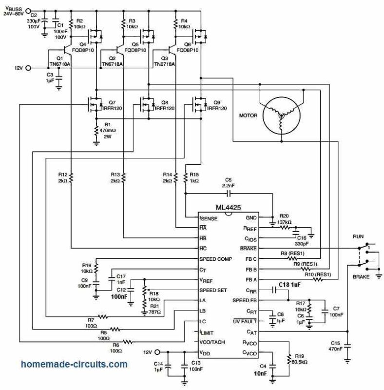
Courtesy: Mouser.com
The system looks pretty straightforward, you just have to solder the shown components in place and quickly start the BLDC operations. It is as simple as switching ON power and seeing the BLDC motor rotate with full efficiency.
The controls are also very easy to understand and implement, the RUN/BRAKE switch enables the motor to continue running as long as the switch is in the OFF position, or not grounded, while the motor is instantly stopped as soon as the switch is toggled at the ground level.
The POT R18 allows the user to control the speed of the motor linearly, simply by moving the pot knob across the specified range.
Main Advantage
The biggest advantage of this 3-phase sensorless BLDC controller is that it does not require the messy sensor based feedbacks from the motor, neither depends on a 3-phase sync signal from the an external source. As can be witnessed in the above diagram, the feedback is achieved from the motor's main 3 phase operating wires via R8/R9/R10 into the designated pinouts of the IC.
This allows the controller to be used with all types of BLdC motors whether or not a sensor is available. If sensors are available from a BLDC, those can be ignored and the motor may be configured without the sensor wires, as indicated in the above diagram.


Questions & Answers
gud day sir i am studing this circuit i want to use it to run my motor but all the transistors and fets listed are sueface mount type yet i want to use these ordinary ones.and also can i run it at around 120v and 1.2kw what should i add thanks sir.
Hi Olupot, the mosfet an BJT values are not critical, you can replace them with any other equivalent which may be easily available in your area….
120V operation may not be possible without a converter, because the unit is designed to work with 80V max
what modification do I need to do about this circuit to drive my washing machine motor of 300v dc (5 amh)bldc motor thanks 🙏
I think you can replace the 80V input with 300V DC input after suitably upgrading all the MOSFETs to 400V rated MOSFETs.
thank you 🙏
thanks alot sir let me do that
Ml4425 is obsolete. Alternative?
unfortunately I could not find any similar high power alternative so far.
Thank you for all these great BLDC motor control projects. I have been looking at theses circuits for a while and can’t see how to apply reverse to any of them. Can you explain how reversing the rotation would work. I would really appreciate the explanation.
You are most welcome, it can be probably done by swapping the set of signal inputs either from the sensors or through back emfs that arrive from the Motor to the IC
Thanks again,I was thinking along these lines. Very much appreciated…
you are welcome!
Yaa swag I made it very good just one thing fishy about 10k pot when im turning just little moter wows then normal can u understand what is this otherwis i found this circuit easy and gooood
Thanks
Thanks Gulabkhan, I am glad you could make this project successfully. Yes while adjusting the 10K speed control the motor speed may fluctuate a bit. You can rectify the fault by using a multi-turn type 10K pot instead of an ordinary pot.
Ok Thanks
I looked everywhere. Where can I get the ML4425 or similar chip?
I think you can find it on ebay….
You can get it from DIGIKEY.
Swagatam can I change the MOSFET to 400-500v so that I can drive it with 310v MOSFET supply input?
Hi Morgan, Yes I think that is possible, you an try that, but first I would recommend testing the circuit using the MOSFETs as exactly indicated in the diagram.
Cool. Found an ML4426 that has a reverse feature…
pdf1.alldatasheet.com/datasheet-pdf/view/75735/MICRO-LINEAR/ML4426IS.html
yep that’s cool, thanks for updating, appreciate it.
How do I figure out the bootstrap capacitor size and capacitor C13 size?
Is the circuit above be use to a fisher pykle direct drive motor if i use 12 to 24 v input. Do you have an idea on how many amp needed to drive the motor. Or do i have to modify the winding to be driven by 12 or 24v
Hi, sorry I do not have any information regarding the specified washing machine motor.
sir
r8,r9,r10 resistor vale send me
Please check the following datasheet, you will find the answer under “Back EMF Sampler”
https://www.homemade-circuits.com/wp-content/uploads/2018/08/ML4425CP-datasheet.pdf
The formula is:
RES1 = 670 Ω ⁄ V x (VMOTOR – 10V)
Hi Swag,
im a RC model aircraft designer/builder. My latest thing is designing/building working hydraulic systems for my projects. For the pump I have been using miniature fuel pumps intended for model turbine engines. These pumps are very expensive (around 500$) and all use brushed DC motors.
I have found a source for pumps/motors in China that are much more reasonable in price and quality is higher but they all use a 3 phase brushless DC outrunner motor. The motor controller for these units must be plugged into the airplanes receiver. Where can I find a three phase DC motor controller that doesn’t use the airplane’s receiver. One that would allow me to simply toggle a switch to turn the pump motor on/off.
Hi Robert, If you are looking for a 3 phase DC motor controller which can be switched ON/ OFF independently with a switch, then you can try the concept discussed in the above article.
Or you can also try the 4rth circuit from this article:
https://www.homemade-circuits.com/three-phase-inverter-circuit/
Hi friend ,
I need to run the 48v 1000watt BLDC motor with out hall sensors so please provide the details for the same.
Regards,
Gopal
Hi Gopala,
You can try the above circuit or the following one:
http://pdf.datasheetcatalog.com/datasheet/MicroLinearCorporation/mXrtruz.pdf
It’s OK? With this controller, can I use a modified engine alternator, creating a system to power the field coil? Thanks.
Sorry, I have no idea about it because not an automobile expert, you will have to consult a qualified auto mechanic.
Hello Swagatam,
I am interested in the Sensorless BLDC Motor Drive. Can someone make the same for me as I will not be able to do the same because I am not a technical person.
Thanks,
Sachin.
Hi Sachin, I am sorry, it won’t be possible for me due to work load. However, since the above design is taken from the datasheet of the IC so you can rest assured it will work without fail if done correctly. That said, normally all circuits will have some minor issues initially, which will have to sorted out carefully, or else even a small mistake from the constructor can prevent the circuit from working or even cause permanent damage to the parts.
Has anyone tried this successfully? If so what was the maximum power rating you could do it for? Please let me know as i need help in this.
Thanks
The design is taken from the datasheet of the IC, which means it is a thoroughly tested and proven design. It will work without fail if everything is done correctly and exactly as shown in the diagram. The MOSFET number is not critical, other variants can be tried with identical specs.
The power will depend on the MOSFET rating. For example if the MOSFET is rated at 200 watts then the circuit will support up to 200 watt load. The MOSFETs must be mounted on suitable heatsink.
Nice one , I love the simplicity of the circuit , thanks for your selfless great input and contribution .
Thank you Rashaka!
hey. kindly let me know the values of C4 & C12 and also R8, R9, R10
C4 and C12 are 10nF and 100nF respectively
R8, R9, R10 can be calculated using this formula
RES1 = 670Ω ⁄ V * (VMOTOR – 10V)
More info is given here:
https://www.mouser.com/datasheet/2/149/ML4425-189510.pdf
thanks so much. I will let you know the end result. Nice time
No Problem!
Hello!
Thanks for reply ,my next confusion is about R1, this is 470m,ohm is this milli ohm or mega ohm b’cause my experience is this mybe .047 ohm am I wright??
Yes R1 is 0.047 ohms
Sir any circuit for sensorless bldc circuit for air-conditioning system for 220 volt input , because now every refrigerator and ac have same concept for compressor operating. This is also good business also
Hi Anil, you can operate the above explained circuit or any other similar design through a 24V SMPS power supply, from a 220V input supply.
Sir I want to operate 3 phase 220 volt BLDC compressor , and this type of compressor use in all ac and refrigerator now these days. So pls make a circuits for 220 volt ac system. Pls reply on mail if possible
Hi Anil, the circuit explained in the above article uses a 3 phase BLDC motor, ans its smps supply can be used with a 220V AC single phase input
Hello swag how ru thank u for this bldc circuit I made it but confused in the value of R8,9,10 & c14 if possible mail me please or watsapp @009203078176990thanks
Hello Gulabkhan,
Please check the following datasheet, you will find the answer under “Back EMF Sampler”
https://www.homemade-circuits.com/wp-content/uploads/2018/08/ML4425CP-datasheet.pdf
The formula is:
RES1 = 670 Ω ⁄ V x (VMOTOR – 10V)
hi.
sir i am khurram shahzad.my question is Will this motor driver run on every motor? My motor 4kw 60v 80amp.BUT i am confused this controller is run this motor (High Current Sensorless BLDC Motor Controller using Back EMF) your driver please guide me my controller is missplace.SIR I am again msg send for you.please replay me.THANKS and solve my problam.
It will work with your motor, but the mosfets will need to be changed accordingly. The P type side must have 4 mosfets IRF9540 in parallel on each channel, and n type must have two in parallel IRF540 on each channel
Thanks alot sir.but update in this all componets name please and value and agin thankx for you replay me.C14 two time write and C12 not name capcitor value and volt.this is all capcitor use 100volt.please update now.
C12 and C14 are not critical, and can be a 0.1uF/100V PPC capacitor….see the datasheet for more details:
https://www.mouser.com/datasheet/2/149/ML4425-189510.pdf
Hello! Me and few of my friends have tried to build BLDC motor driver without HALL sensors using Arduino board as a substitute. However, while we did manage to make our testing motor rotate, it rotates much slower than it should have (roughly just 2-3 rps) and the Arduino board replies quite slowly to our signals to speed up or down without any visible effect. We’ve examined the entire schematics, but can’t figure out what could possibly be the problem. Do you have any advice on what might be the issue? Thank you in advance for any reply!
Hi, I am not good with Arduino coding, so it will be difficult for me to suggest you a proper solution.
Hi Swag;
I am building this circuit and would like to ask you on R1 wattage rating. How does it was determine?. Say my motor is 48V and current 10A. As a rule of thumb, the R1 wattage rating is about 48Vx10A = 480W or just take 500W?. Kindly advise. Thank you in advance.
Hi Fadzil, R1 wattage will be equal to the voltage developed across R1 and the maximum trip current of the load. How much voltage is needed to develop across R1 will depend on the I(sense) pin specification. Suppose the I(sense) is specified to be triggered at 1 V, then the wattage of the R1 will be 1 x max trip current. If the max shut down current is 10 amp then R1 will be 1 x 10 = 10 watts and so on.
Hi Swag;
I found it very strange the circuit have continuos 12Vdc connect to the base of the transistor and the signal connected to the emitter side. I saw a lot of H-bridge controller using the base of the transistor for a signal input but not this one.
Fadzil, the design is suggested by the manufacturer datasheet, may be they have a specific reason for this.
Good day sir, please sir can the mc33035 ic be used to generate pmw to drive external NPN fets to control brushed DC motor and making use of external current sensor like (allegro sensor ACS758) which is rated for 200 Amps to monitor the motor current through pin 9 (csensin).I would be happy if you can help me out with the circiut i just smoked my expensive Chinese DC controller sir
Marvin, I am not sure about that, because these are specialized ICs, designed to work only with the specified fixed parameters, so modifying there working can be risky
Hi, firstly great site and some interesting circuits. I have converted a bike with a cheap bldc hub motor/controller kit. It works ok but a few months of use and I have already killed a speed controller so I don’t hold out much hope for the new one I just fitted lasting too long. I fancied a go at building one from a circuit. My existing bldc hub motor uses hall sensors and I believe the windings are connected in delta config (it only has 3 heavy duty drive wires). It runs from 36v @20A. While I understand the circuit shown here uses the normally undesirable back emf to sync up the drive so I can ditch the hall sensors I don’t understand how a star connected motor with the central common connection not connected to anything else works. Won’t any drive to the motor always energise 2 motor coils at once? Have I just misunderstood the diagram and the common centre tap is connected to gnd? In any case I am assuming it can only be used on bldc motors with star connected windings?
Hi, thanks, yes that’s correct. The two stator winding will be in series at any given instant of a phase input, but the transition will be very smooth across any two winding, creating a seamlessly transiting or rotating magnetic field on the rotor.
Greeting Swagatam, can you please confirm the value of RES1 = 670Ω ⁄ V × (VMOTOR – 10V) if the VMOTOR = 300V?
647 ohms, if the supply V is also 300V
Greeting Swagatam, many thanks for your prompt response, much appreciated.
Glad to help, Santos!
Hello,
I need to drive a high Kv sensorless BLDC. It is easy to buy a cheap drive for up to 60 V.
But my back EMF amplitude will be 140 V.
How to do it?
Can I use that 60-Volt PCB to drive my external MOSFETs capable to, say, 250 Volt?
Maybe to simply use 2ED28073J06F-600 V Half Bridge Gate Driver to interface the PCB with HV MOSFETs?
Please advise.
Thank you very much!
Hello, yes you can drive external high voltage MOSFETs using a 60 V driver, but it is also possible to eliminate the back EMFs simply by adding external diodes across the existing MOSFET, drain/source pins
How come the assembly is not explained or at least the list of parts with the diagram, I do appreciate the diagram but was reading then all the sudden it was over thought I accidentally skipped it but after re-reading it I know I didn’t. I just thought this site was kinda like instructables. I’m pretty new to building electrical circuits and was looking forward to the step by step, guess only way to learn is to try until succeed
I have not built this project myself, so I cannot provide a step by step tutorial. Maybe You can refer to the datasheet of the IC for the detailed info.
Am a beginner in electronics and would appreciate if the missing values are pre-installed and later find a way on how to calculate to meet the load requirement.
I want to run a car alternator as BLDC motor ,what values can I put at C4,C14,C12 and RES1-3 to run it at it’s full speed(3000rpm)?
The above project is actually not recommended for beginners, since it has many complicated aspects to be taken care of.
you can refer to the following datasheet to know exactly how the missing values of R8, R9. R10 can be calculated
https://www.mouser.com/datasheet/2/149/ML4425-189510.pdf
Hello, could you please provide a BLDC controller (high current) circuit with hall effect sensors? need 48V, up to 50 A current.
Hello, you can try the following concept:
https://www.homemade-circuits.com/48v-3kv-electric-vehicle-circuit/
Thank you for your response sir.
Hello
Can i use d667 against tny6718 b’cause tny is not in our karachi market please guide me
you can use any transistors which an handle 100 V. If D667 is rated to handle 100V then you can use it.
hi
I need to run a bldc compressor its voltage is 60-220v dc what kind of mosfet i use plz give a reply
i hope to build this drive
Hi, what is the wattage rating of the motor?
Hello,
thank you for sharing!
I would like to replace a 24V DC/15W motor equipped with a tachogenerator by a brushless one, the stability of the rotation speed is very important, which circuit would you recommend?
A circuit with L6235 and Hall sensors or the circuit equipped with the ML4425 can do the job just as well, although simpler?
Thanking you in advance,
José
Hi, I think the circuit explained in the above article can be perfectly implemented for your sensorless BLDC motor application. So, the ML4425 is the one that might work for you the best!
hi, sarin here
this sensorless BLDC circuit have two C14 and C4,C12 not mensioned value, can you explain this.
Hi Sarin,
I have updated the required information in the diagram…you can check it now.
Sir,
I have completed this circuit and start successfully, but one of N-type mosfet become over heat . what should I have to do to over come this problem and motor starts with jirk.
Sir please guide me.
Thanks,
Hello Pir Bukhsh,
This circuit is taken from the datasheet of the IC so it is beyond my control, and I cannot suggest much. If one MOSFET is heating up then you can try replacing it and check the results.
Make sure to mount all the MOSFETs on heatsink
Dear Sir, I have designed the circuit and try to run it but it gives only hissing sound but do not start. What should I do? Please give your value able suggestion.
Hi Pir Buksh, the above circuit was taken from the datasheet of the manufacturer, so unfortunately I cannot help much with this design. I think if you build it correctly then it should work without fail. You can refer to the original datasheet and see if this help:
https://www.mouser.com/datasheet/2/149/ML4425-189510.pdf
Thanks Sir,
This problem is solved and the other is when motor starts it takes three to four jirk just like dek, dek …. and then starts and same is the case when I slow down it with the variable it also starts jirking ( dek, dek…) but when I increase its speed it becomes smooth and steady. Please guide if you have any idea.
Thanks,
Pir Bukhsh,
Try adjusting the value of C18. Either increase it or decrease it and check how the motor responds.
Thank you Sir, one problem is solved. But, when the motor start it begin to jerk two are three time and them become smooth. What should I do now.
Thanks,
Hi Pir, sorry, I have no idea about it, because this circuit was taken from the datasheet, and the datasheet does not have any information about this issue.
Can I get the pcb for this sensor less BLDC controler? Please guide me on my mail ID. Thank you.
Sorry, pcb is not available for this project.