This power interruption alarm circuit will alert you whenever there's a power failure or an interruption in the mains. In some special conditions it becomes imperative to know whether the mains that powers some important system or circuit is absent.
By: Manisha Patel
How the power failure alarm works
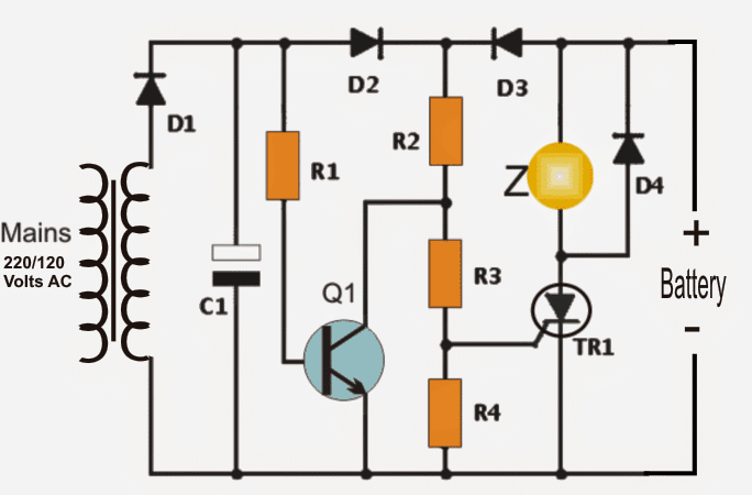
This proposed circuit is connected to the power mains via the transformer T1. The AC voltage is rectified by the diode D1 and is filtered by C1.
As long as there is a voltage level present at the anode of D2 (around 12 volts), transistor Q1 is able to conduct maintaining a negligible voltage at the gate of the SCR (TR1).
Thus the SCR is not able to get triggered, ensuring no triggers and no alarm tones.
It can be seen that the SCR is permanently attached with a 9 volt PP3 battery.
In an event of a mains failure, the voltage from the transformer disappears, the transistor Q1 is instantly cut-off, diode D2 ensures that no current is able to reach Q1 base from the battery power.
Also, The battery forward biases diode D3 and a current flows through R2, R3 and R4 resistors.
This situation raises the voltage level at the gate of TR1, activating the SCR and the attached buzzer that warns of the situation or the absence of mains voltage.
The moment the power returns, the signal error message does not disappear because the thyristor holds itself in latched condition due to its inherent properties (with DC supply SCRs once triggered stay latched permanently), even though its gate now is rendered with a zero voltage.
In order to cut of the alarm and restore the condition, it may be only necessary to disconnect the battery supply momentarily via a switch (not shown in the diagram) placed in series with the 9 volt battery or in series with the thyristor anode or cathode.
Note: The buzzer may be replaced by a relay for enabling a visual warning or both.
Circuit Diagram
Bill Of Materials for the proposed power interruption alarm circuit
- 1 resistor R1 = 12K
- 1 resistor R2 = 2.7K
- 2 resistors: R3 = R4 = 1K
- 1 NPN: BC547
- 1 470 µF/25V
- Four semiconductor diodes: D1 = D2 = D3 = D4 = 1N4007
- 1 Thyristor TR1: C106Y1 (NTE5452)
- One transformer 120/240 VAC to 9 VAC or more than 500 mA
- 1 buzzer 6 or 9 volts
- 1 PP3 9 volt battery.
Also Read: Power Failure LED Indicator Circuit


Questions & Answers
I have a travel trailer and I need to know when the power goes out to determine if my freezer food has spoiled!
That’s great thank you for your quick response.
You are most welcome!
I think the second circuit from the following article should do the job for you. You can replace the LED with a 3V buzzer.
https://www.homemade-circuits.com/5-useful-power-failure-indicator-circuits-explained/
Will this circuit work with a solar/battery backup system? Once grid is down, battery system is automatically switched over. The problem, we don’t know when we are on battery backup and would otherwise turn off unnecessary appliances.
Do you either build such a circuit or sell a kit? I am not very versed in building such devices and not even sure where to get the components to do so.
Thanks, Roy
Sorry, providing a ready-made kit for this circuit might not be possible. You can hire a freelance engineer to do it for you.
Yes, the circuit will work with solar battery system also.
Not familiar with circuitry.Should the resistors1/4 or 1/2w be.
Than you so much
When not specified they can be assumed as 1/4 watt resistors
Thanx for your quick response,my first lesson in circuitry ????
Hi sir
I want to set the alarm on the compressor in my company when the electricity fluctuates the compressor trips down and wont start automatically so i want set the alarm on fault condition and on shutdown
thanks
Hi Asad, do you want an external alarm to keep sounding as long as the compressor is turned OFF?
Hello sir. I need similar circuit but this time when mains is present a fading alarm sound. In such a way that when mains is restored the alarm sound for a short while. Looking forward to your response, thanks.
Hello Chris, you can remove everything from the circuit except R1, C1, and connect the buzzer between collector of the transistor and the positive line.
and connect the base of the transistor to R1 via a 100uF capacitor…also connect a 10K from the junction of R1 and this 100uF capacitor to ground
I need a alarm circuit for AC 3 phase under voltage and over voltage i mean when voltage is below 190v alarms sounds and when voltage is above 250volt AC alarm sounds.
you can try the following concept
https://www.homemade-circuits.com/2011/12/simple-mains-high-and-low-voltage.html