The discussed circuits are designed to discourage dogs from barking in the selected zone by the generation of a synchronized ultrasonic sound waves in response to a few initial barking of a particular dog.
The circuits explained below when correctly optimized will produce a high pitched ultra sonic sound each time it senses a dog bark. Since the sound is in the ultrasonic range will be inaudible to humans, and audible to only dogs present in the vicinity.
Manual High Power Push-Pull Dog Repellent Circuit (Tested)
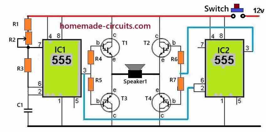
The ultrasonic dog repellent circuit shown below is a highly effective design due to its H-bridge configuration, which generates a powerful push-pull action on the attached ultrasonic transducer.
The push-pull mode creates a pumping action on the transducer causing massive thrusts on the generated ultrasonic pulses.
This circuit was practically tried on dogs and cats with positive results. The testing procedure required a lot of hard work and dedicated effort, which was thoroughly implemented by Mr. Emad, who is an avid reader of this blog and great electronic enthusiast.
Circuit Diagram
How the Circuit Works
The IC1 is configured as a normal IC 555 astable circuit which generates square wave pulses at its output pin#3.
The resistor R1 along with the R2 pot value determine the frequency of IC1 output.
This output from IC1 is applied to T1, T3 driver transistors of the H-Bridge configuration.
This frequency at pin#3 of IC1 is also fed to the pin2 and pin6 of another IC2 555 stage.
This 555 IC2 is configured as a set-reset circuit, which works efficiently to enable the correct functioning of the H-bridge transistor driver.
The output pin#3 of IC2 is connected with T2, T4 which forms the other set of driver transistors of the H-bridge circuit.
The IC2 ensures that during the ON periods of IC1 pin#3, the IC2 pin#3 is OFF, and vice versa.
This ensures a safe operation of the H-bridge transistors which always operate diagonally, causing an alternate push-pull or reverse forward conduction of the load, which is a transducer in this circuit.
The push pull action of the transducer diaphragm causes powerful thrusts on the generated pulses which ultimately helps to create a strong repelling action on animals like dogs and cats.
Parts List
- R1 = 1k 1/4 watt = 1
- R3 = 4.7k 1/4 watt = 1
- R4-----R7 = 1k 1 watt = 4
- R2 = 20k pot = 1
- Capacitor C1 = 3300 pF Ceramic Disc = 1
- Transistors, T1, T2 = TIP142 = 2
- Transistors, T3, T4 = TIP147 = 2
- IC1, IC2, IC555 = 2
- Push Button 5 amp = 1
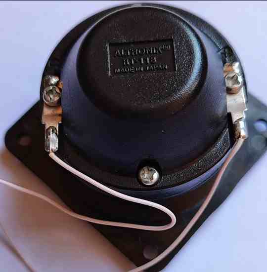
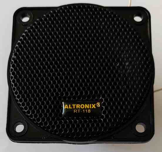
- Speaker1 is a 8 ohm High Power Tweeter, as shown below = 1
Tweeters used in the above prototype
Using Arduino
The above concept can be made even more effective and customizable when built using an Arduino. The complete wiring and circuit diagram is given below:

Below is a simple Arduino code that will generate a square wave with adjustable frequency (1kHz to 25kHz) and output staying ON for adjustable time between 1 to 5 seconds.
Full Arduino Code
const int outputPin = 9;

const int potFreqPin = A0;   // Pot for frequency
const int potTimePin = A1;   // Pot for ON-time duration

unsigned long halfPeriod;    // Half of square wave period in microseconds
unsigned long onTimeMs;      // How long to output the square wave
unsigned long offTimeMs = 1000; // OFF time fixed to 1 second (can also be made variable)

void setup() {
  pinMode(outputPin, OUTPUT);
  pinMode(potFreqPin, INPUT);
  pinMode(potTimePin, INPUT);
  digitalWrite(outputPin, LOW);
}

void loop() {
  // Read and map potentiometers
  int freqRaw = analogRead(potFreqPin); // 0 to 1023
  int timeRaw = analogRead(potTimePin); // 0 to 1023

  int freq = map(freqRaw, 0, 1023, 1000, 25000);         // Frequency: 1kHz to 25kHz
  onTimeMs = map(timeRaw, 0, 1023, 1000, 5000);          // ON-time: 1s to 5s
  halfPeriod = 1000000UL / (2 * freq);                   // Half-period in microseconds

  // Generate square wave for ON duration
  unsigned long startTime = millis();
  while (millis() - startTime < onTimeMs) {
    digitalWrite(outputPin, HIGH);
    delayMicroseconds(halfPeriod);
    digitalWrite(outputPin, LOW);
    delayMicroseconds(halfPeriod);
  }

  // Output OFF period (fixed 1 second or customizable)
  digitalWrite(outputPin, LOW);
  delay(offTimeMs);
}
Code working Details:
- Only one output pin#9 will generate the square wave pulses.
- Frequency adjustable from 1kHz to 25kHz using one potentiometer.
- Pulses will turn ON and OFF intermittently with ON-time adjustable from 1 to 5 seconds using another potentiometer.
- During OFF time, the output pin will remain LOW.
Automatic Dog Bark Terminator Circuit
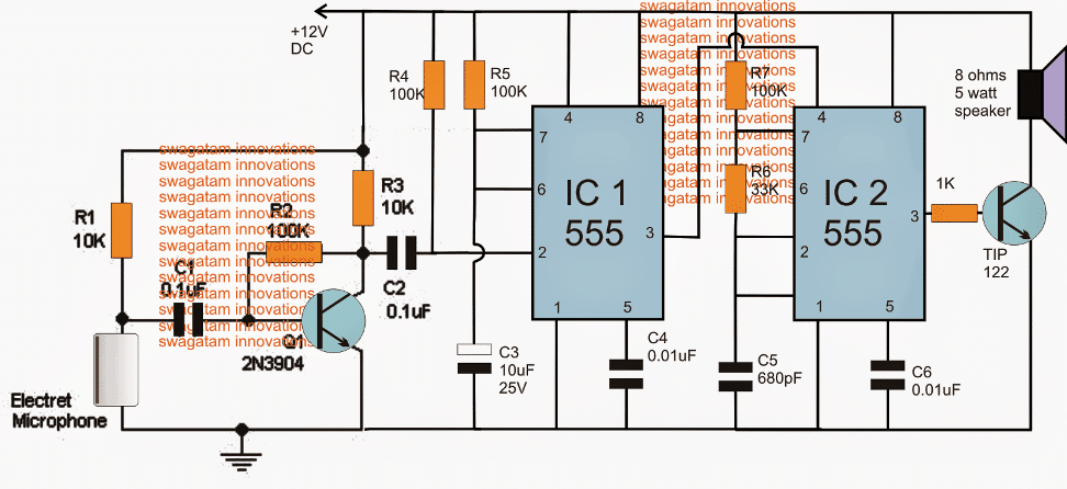
Note: Please use 1uF capacitor for C2 to ensure a foolproof triggering of the IC1 stage...
Parts List
- Resistors all 1/4 watt 5%
- R1, R3 = 10K
- R2, R4, R5, R7 = 100K
- R6 = 33K
- R7 = 1K
- Capacitors
- C1 = 0.1uF, disc ceramic
- C2 = 1uF/25V
- C3 = 10uF/25v
- C4, C6 = 0.01uF ceramic
- C5 = 680pF ceramic
- Transistors
- Q1 = 2N3904 or BC547
- Q2 = TIP122
Referring to the above shown dog bark inhibitor circuit, we can see three distinct stages involved, the sound sensor and preamplifier circuit using the Q1 and the electret MIC stage, the monostable stage using IC1 and the associated parts and the ultrasonic sound generator stage using the IC2 and the speaker driver stage.
Whenever a dog barks, the Mic detects it causing a sequential low and high pulse at the base of T1. T1 responds to this and produces an equivalent amplified signal across C2, which in turn triggers the pin#2 of the monostable IC1.
The above action forces IC1 to produce a high at its pin#3 for a period determined by the values of R5/C3.
This high at pin#3 of IC1 enables the reset pin#4 of IC2 to become active thereby allowing the astable IC2 to supply the ultrasonic pulse at its pin#3, which is appropriately amplified by the associated TIP122 transistor, driving the connected speaker.
The speaker vibrates at the specified amplified level throwing the ultrasonic sound in the direction where the dogs need to be driven away.
The above sound waves is supposed to fluster the dogs and cause a lot of disturbance in their ears due to its high pitched sound, and also due to its synchronized effect with the dog's own barking sequence.
Actually the above dog barking stopping device might respond to all types of high dB sound levels, however since it won't be audible to a human ear this will never be an issue, and may be ignored.
Making the Circuit more Sensitive
If you find the above dog barking prohibitor circuit not responding to barking signals or any sound distant signals correctly, then you must try upgrading the MIC stage with an IC based MIC amplifier stage as shown in the following image:
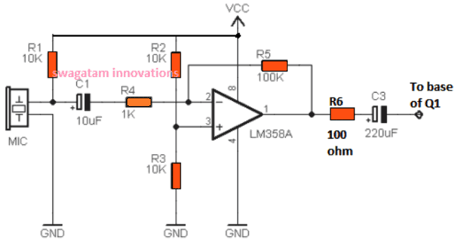
Once you build the above circuit, you can eliminate or remove R1, R2, C1 from the first circuit, and replace it with the mentioned op amp based MIC amplifier circuit and configure the C3 output from the op amp with the base of Q1.
This upgrade will ensure that the circuit responds appropriately even to weak sound signals, specifically dog barking sound during night time, and trigger the IC 555 stages for the intended results.
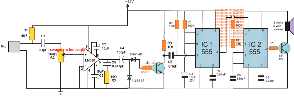
Increasing the Range over 50 Meters
To make the above design respond to dog barks at distances over 50 meters, the following modified idea could be tried.
However this circuit being extremely sensitive could get triggered by other forms of sounds in the vicinity.
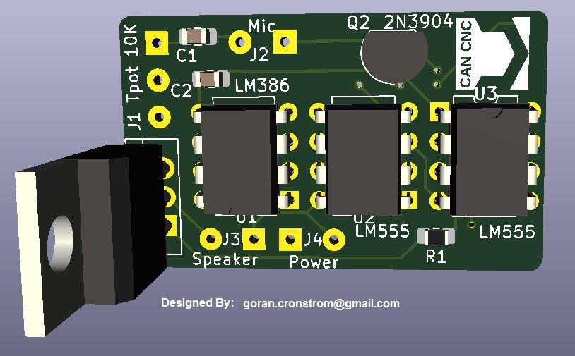
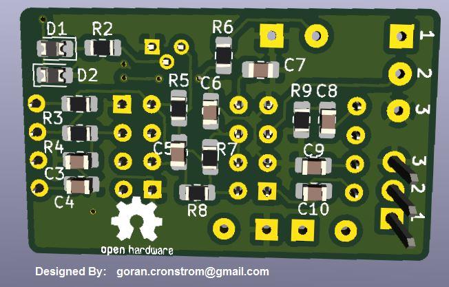
PCB Design
UPDATE: A Much Simplified Design
A simple transistorized circuit presented below can be used as effectively as the above designs for repelling dogs or any other animal away, from a distance.
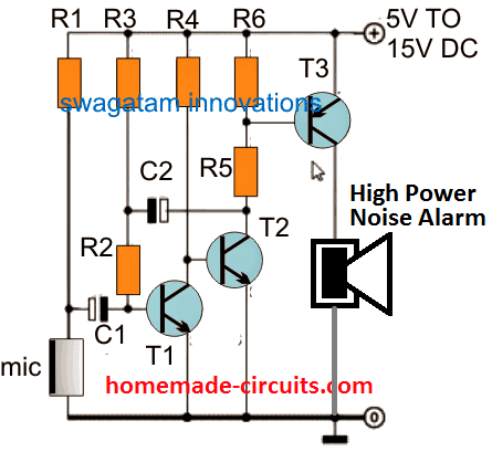
The parts list for the above design is shown below:
- R1 = 5k6
- R2 = 47k
- R3 = 3M3
- R4 = 33K
- R5 = 330 OHMS
- R6 = 2K2
- C1 = 0.1uF
- C2 = 1uF/25V
- T1, T2 = BC547
- T3 = TIP127
- D1 = 1N4007
- Mic = electret condenser MIC.
If you wish to use some other form of deterrent instead of the indicated high power alarm, you can replace the speaker with a relay and connect the desired load with the relay contacts. The relay based design is demonstrated in the following diagram:
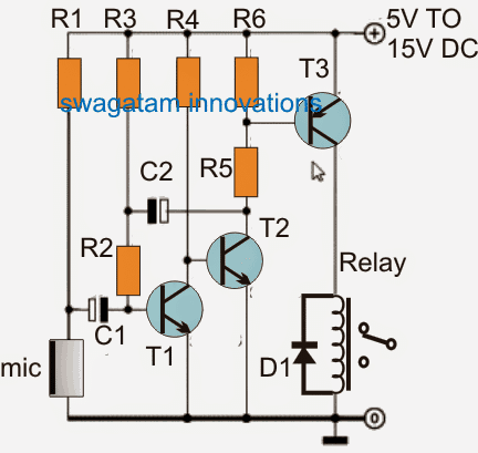
The parts list will be the same as above, except the T3, which can be replaced with BC557 transistor.
How it Works
As soon as a relatively loud noise such as a dog barking sound is detected by the MIC, the signals are amplified by the subsequent BJT stages, which activates the relay momentarily. This momentary delay of the relay activation is determined by the value of C2, which can be adjusted to best suit the application.
The relay contacts can be hooked up with a suitable high frequency circuit, such as an electronic dog whistle.
Improving Further
In the above design, the relay can be eliminated, and the T3 collector output can be directly used to activate the IC 555 frequency generator circuit, as shown in the following figure:
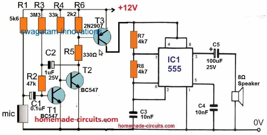
Dog Deterrent Circuit
Are dogs from the neighborhood constantly digging up your front lawn? The following high-pitched screamer can effectively deter them!
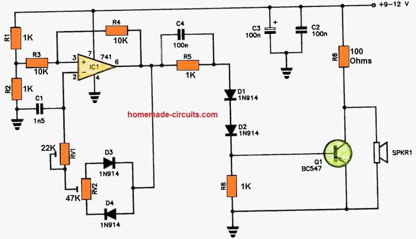
The IC1 (Integrated Circuit 1) is configured as a high-frequency oscillator, producing narrow pulses. You have the flexibility to adjust the frequency using RV1 and fine-tune the mark-to-space ratio with RV2.
IC1's output is channeled to the base of Q1 through R5 and D1-D2. The pulses at the collector of Q1 drive SPKR1, which is a piezo horn tweeter.
These sounds operate at frequencies well above our hearing range and are exceptionally loud, making them audible to dogs and other garden pests with four legs.
The inclusion of diodes D1 and D2 serves to enhance the turn-on voltage for Q1 because IC1's output doesn't reach all the way down to zero volts.
To achieve the best results, some trial and error with RV1 and RV2 settings may be necessary to optimize the device's performance.


Questions & Answers
Hi swagatam,
Can you explain the circuit with PIR sensor instead of electret MIC.
Hi Sharaf, for what application do you intend to use it? please provide with more details so that I can understand it better.
Hi Swagatam,
If any dogs are enter to the coverage area immediatly trigger and generate ultrasonic sound to repel the dogs.
Hi Sharaf,
a PIR will detect all types of living beings including human beings, so that will not work….
…warm blooded living beings
Hi Swagatam,
We are facing lot of problem with street dogs and those are tresspasses to the residence area, especially in night time.
So, if we use PIR the device can work only the particlar time instead of full time.
OK in that case you can use the following circuit
https://www.homemade-circuits.com/2014/09/automatic-pir-controlled-fan-circuit.html
remove the relay, we don't want it here, also disconnect the emitter of the transistor from its ground position and connect it with the IC2 pin#4 from the circuit explained in the above article.
so we'll require only the IC2 stage from the above article circuit and integrate it with the PIR circuit from the given link, as explained.
Thanks a lot for your support and help……….
what is electrec mic? How to test this circuit? When mic detect dog sound at what time waves are generated?
electret mic is small mic which are commonly used in amplifiers and FM hand held transmitters,
connect an LED in series with the TIP122 base whenever it lights will indicate the working of the speaker.
clapping near the mic should initiate the triggering process….
in above circuit what is range of sound will be heard by dogs? also what is effect on another animal? is this circuit activate for all sound? means human noise also activate this circuit? How to make possible range?
As in our farms there is lots of peacock wonder at the time of harvesting can this circuit is applicable for this condition?
the range will be around 10 meters, other animals may not be affected because they may not possess high sensitivity to sound frequencies as dogs normally have.
peacock cannot be driven using this circuit because the hearing range of birds are quite similar to the human beings except bats
dear do you have a ultrasonic circuit for elephant. in our country daily one or two people are get dead due to wild elephant. request help. i noted that elephant hearing frequency is 16-12000hz.
You can easily make it by using a 555 IC along with a speaker amplifier stage, quite identical to the IC2 stage as indicated in the above article.
the frequency can be set by suitably adjusting the values of R7 and C5 …until the effective note is achieved for driving of the animals.
the range will depend on the power of the selected transistor and the wattage of the speaker, higher wattage will enable longer ranges.
Is the IC555 is LM555?
any 555 will work
Can you please provide more info about the MIC and Speaker? any part number?
Thanks,
you can see the pics below:
MIC
reviseomatic.org/help/e-components/Electret-mic.jpg
Speaker (tweeter)
img.weiku.com/a/001/812/KTV_tweeter_speaker_T031402__3659_7.jpg
Sir, i made this circuit but i am facing some problems. When power supply is on speaker get some vibration continuous, no any sound but feels vibration. When i remove mike speaker vibration stop. Please help me for this. Is this vibration is capable for generating sounds for keep away dogs.
Ashok, the response that you are getting from the speaker looks OK, but it should not happen continuously…rather only when a sound hits the MIC.
I think the sensitivity of the mIC circuit could be too high. try reducing C1 to 0.01uF or 0.001uF and check the response
Sir, i changed C1 0.1 to 0.01uf, this time no vibration sense in speaker. When i clap for sound then nothing happen with speaker.I inspect the circuit carefully i found one short connection at IC1 3 pin to IC2 pin3 which is directly activate base of TIP122. I made correction but after that circuit is not work.
Ashok, a short circuit of any kind across the ICs can damage the devices…so better change the ICs again and test.
this time do not connect the MIC stage, rather initially test by manually shorting the pin#2 of the IC to ground (momentarily) and see the response on the speaker…
…sorry, correction: test by shorting R3/C2 junction of IC1 with ground
Hi, That probably means that the MIC stage is not powerful enough and needs to be upgraded so that it becomes more sensitive for converting the sound signals into triggering signals for the IC 555, I will try to update the above article with the mentioned improvements soon.
you are welcome, actually any opamp will work here, you can easily replace it with an ordinary IC 741
that's great, now you can confirm the final results with an actual dog barking
yes that's possible, you can use a pot in place of R2 and tweak to keep the opamp at the verge of conduction and make the circuit very sensitive.
additionally you can use a Darlington transistor for Q1 for enhancing the sensitivity of the unit
you can use 9V instead of 12V without any modifications, but make sure the current is sufficiently high so that the speaker can be driven with the required amount of power…a 9V PP3 battery will not work.
click the images to enlarge them
The degradation could be due to a slow internet connections, anyway glad to know it has been rectified now and the image is now clearly visible to you.
Hi Swagatam,
I would like this unit to have a range of 50 meters. What modification should I make to achieve this. Also can I use a Compression driver instead of a speaker as it appears that Compression drivers are much more efficient.
Regards
Jan
Hi Jan, you can try the LM386 based last circuit from this article, to enhance the sensitivity of the entire design:
https://www.homemade-circuits.com/2012/08/ic-lm-386-datasheet-explained-in-simple.html
use the R1/C1, and the MIC network which is shown in the last circuit from the above "DOG Barking" article, and connect the C1 end with the volume control of the linked LM386 circuit.
The speaker point outputs from the LM386 modified design can be finally integrated with the base of Q1 as presented in the first circuit diagram of this particular page
Hi Swagatam,
Thank you for your reply. Does this mean that the speaker range will also be 50 meters.I read some were that the current design is effective for approx. 10 meters. I need to increase this to 50 meters.
Regards
Jan
Hi jan, according to me the amplification power could be increased by replacing the speaker transistor with a 2N3055 transistor and using a small value base resistor of around 100 ohms…this will hopefully make the output strong enough to carry it up to 50 meters
Hi Swagatam,
I am a bit confused. In your explanation you say “ use the R1/C1, and the MIC network which is shown in the last circuit from the above “DOG Barking” article, and connect the C1 end with the volume control of the linked LM386 circuit. Is this pin 3 or 5 on the LM386? Does Last cct refer to the “Making the cct more sensitive OR the main cct with the two 555 timers.
Your assistance will be much appreciated.
Regards
Jan
Hi ajn, I have updated the required diagram at the end of the post, please check it out.
…you ca use BC547 for Q1
Hi Swagatam,
Thank you for the revised CCT.
Regards
Jan
You are welcome Jan!
Hi, yes a tweeter would respond better than an ordinary speaker, however I was expecting an almost inaudible output from the speaker, because the IC2 is set at around 13kHz which can be hardly heard by an human, I think you might want to adjust the R/C components of the IC2 a little more to make sure that humans do not hear it but dogs do.
yes if it's a normal beep then your dog will not be impressed, it has to be something more irritating. Actually the dog will get surprised only when the sound from the speaker responds and coincides with its own barking, that's exactly when the dog might start getting too nervous 🙂
Hi Swagtam
How can i make this circuit work permanent without sensing the dog’s bark ?
Good question Yousef,
you can do it simply by using only the IC2 stage, that’s all….
Hi Swagatam,
I know very little about piezo disc transducers
I was wondering if the speaker can be replaced by a transducer. Do you think this can work?
Your opinion will be much appreciated.
Regards
Jan
Hi Jan , yes definitely the speaker can be replaced with a transducer, however it will need to be complemented with a matching parallel inductor so that the oscillations can be optimally amplified.
Thank you for your reply. So how do I calculate the value of the inductor?
Regards
Jan
You can purchase it readymade from your local electronic dealer…or from any online store, you just have to mention “piezo buzzer coil” and you will able to easily find it
Hi Swagatam, I have finally put this circuit together & seems to be working, but I can hear the sound although quite high in pitch, also I will need to build the additional Mic amp circuit as the current one seem not very sensitive.
I would like to ask for your help as to some mods I would like to make to change its operational characteristics.
I have noticed that when activated the sounds is on for a short time period which can be adjusted by changing R5 & C3, is there a change that can be made to have it operate for as long as it is powered on? also I need to be able to have its frequency adjustable, your help would be much appreciated, Regard Rick
Rick, you can do it by adding the following latch circuit between IC1 and IC2.
https://www.homemade-circuits.com/2011/12/simple-and-useful-transistor-latch.html
you can remove the relay from the design.
in the dog barking circuit disconnect pin#4 of IC2 from IC1, and connect it with the collector of the PNP.
connect the base of T1 in the latch circuit with pin#3 of IC1.
in the latch circuit preferably remove C1 from the shown positive and place it across base/emitter of T1.
Hi Swagatam
Thank you for the info on the Latching circuit, I will give that a try, If I may ask how the frequency output can be adjusted/variable to a higher pitch as I can hear it so I figure it may not be high enough to do its job.
Hi Rick, to increase the output frequency you can decrease the value of C5 to some lower value…. You can try reducing it to 470pF or 330pF and see the effect.
for getting a variable option you can use a pot for R7, but make sure to add a 1K resistor in series with this pot.
Hi Swagatam
Thank you very much for your quick reply, will give all your suggestions a go, thank you once again, great wed site, Rick
You are most welcome Rick!
Hi Swagatam
I have been reading the request from Jan on how to increase the output for a 50 meter range using a 2n3055 & 100 ohm resistor, I have tried this but i think its over loading my 50 watt piezo speaker, would I be correct in thinking this? if so what do you think the output is with that setup & what size piezo would be needed? thanks for your help, Rick
Hi Rick, By overloading do you mean your speaker is warming up or is the sound quality breaking of?
Anyway, you can control it by increasing the 100 Ohm base resistor of 2N3055 to some higher value, may be upto 1K or even 4k7 etc until the current is no longer able to increase beyond the specified safe limit.
Wow, thank you for your super quick reply, will try with different value resisters & see what happens, thanks again for your excellent support to the electronically challenged like me, Rick.
Sure, please go ahead Mr. Electronically Challenged, I liked this phrase 🙂
Wish you all the best…
dO YOU HAVE THE DESIGN IN eAGLE
sorry, I don’t have it…
Good morning,
Please provide a detailed parts list or the price for a completed kit. Dog Bark Terminator.
Thank you, dominic.
Hi, you will find all the parts given in the diagram itself, here all resistors are 1/4 watt rated and all the capacitors can be 25V rated
Thank you for your help. Dominic
Hi Swagatam,
I’m just making this circuit, one question I have is can I mount the speaker in pvc tube to make it directional would that effect the output from the speaker
Hi Iain, actually that’s a good a idea, and would prevent the sound from returning back to the MIC…… although the returning sound won’t impact the circuit, still using a PVC pipe would make the system more efficient.
Hi, do you have a pcb diagram or veroboard layout for your dog bark stopper? Would be appreciated if you have.
Hi, I am sorry I have not yet designed a PCB for this project.
Hi!
I´ve just done a proyect in Kicad and Freecad, where can i upload the files for it?
I also took a nice screenshot of the 3D view of the board.
Brgds Göran
Swagatan, can the optional circuit to increase sensitivity be powered with a 12 VDC supply as the mais circuit?
Thanks
Hi Paulo, yes 12V can be used.
you can also try the first circuit from this article instead:
https://www.homemade-circuits.com/simplest-sound-activated-relay-switch/
Remove the relay and connect the collector of the PNP with the base of 2N3904 in the above circuit.
C2 in the linked circuit an be removed.
Thanks for the quick answer!
Swag,
A misalignment of the lines connecting to pins 2 and 6 of IC2 on the drawing brought me a doubt concerning these points.
Am I correct in assuming that pins 2 and 6 of IC2 both connect a single point between R6 and C5?
Thanks again.
I am sorry about that, yes you are right they both connect at the junction of R6 and C5
What is want a circut board that just triggers when barking occurs. Want to link to self defense dog vest. Dog barks taser set off. Other dog gets shocked while they are attacking. Was thinking taser vest. Any help would be great.
I have updated the required design at the end of the post, but please do not use a taser, you can use something else instead.
I’m interested in making the basic whistle. Can I run this through an external amplifier?
And just via the on/off.
you can apply the output from the 555 astable to an amplifier for getting a whistle sound.
Who would be able to make one or two of these for me? In Colorado.
The neighborhoods available to elderly me for health walking have many obnoxious barking dogs. I want a handy/portable bark stopper that I can use while walking; range about 50 feet.
Im interested in buying one of these. Would you be willing to make one?
I am Sorry, we don’t sell assembled kits in this website!
Dear swagatam
In the first circuit only ic2 stage using for permamently working is enough?
There are a lot of remote dog bark devices on the market. Because you have extensive experience in their electronics, potential purchasers of such devices would benefit greatly from your evaluation of their respective efficacy and utility. You could do U-Tube presentations and perhaps interest an investor to partner with you in making and selling those of your design, or a corporate sponsor in evaluating different brands. yourmanufacturer in making the best designone of your design
Thank you for your valuable feedback, I’ll surely consider them. Appreciate your thoughts very much!
I strongly support what William Ballough said above. There is a significant untapped market, worldwide, for powerful ultrasonic AntiBarking devices that really work. In case you are interested in discussing about it, please contact me in private by my email. I have extensive knowledge on this matter.
I appreciate and agree with your suggestions, I will surely think about it.
Hi swagatam,
Congratulations for your excellent site and specially this AntiBarking circuit.
I have a simple request if possible: Could you please provide me with a design on how to eliminate the speaker and instead include a group of at least 2 two piezo tweeters? I really need to make it as loud and powerful as possible and I,m getting conflicting suggestions elsewhere.
Thanks a lot.
Thanks Malcolm, The speaker can be simply removed and replaced with an appropriately rated tweeter. The circuit frequency being very high will perfectly complement the tweeter specs and generate the required frequency efficiently.
The transistor driver will make sure the tweeter is driven with sufficiently high output. Alternatively you can replace the BJT with a MOSFET for getting more powerful output
Thank you very much for your reply. I wish you all the best, sir.
It’s my pleasure Malcolm!
What frequency is it emitting?
you will have to experiment with the frequency to test which frequency deters the dog the most
Hi,
So its variable which is necessary.
Which frequencies does it use?
If suitable i will arrange for it to be assembled.
Thanks.
Hi, anything between 15kHz and 25kHz should work, but this will need to be tested with real dogs
Hi,
Prompt replies youre providing is greatly appreciated.
Thanks.
My pleasure!
OK– where can I buy the supercharged version. Need it today!
Thank you for the circuits. I’ll ask my husband to make one. My question is, I will be able to hear it?, because he tryied others and we can hear the high pitch.
You are welcome! You can set the frequency at 13 kHz which will hardly audible to the human ears. Just make sure to use powerful tweeters as the speakers.
I’m concerned that the square waves from the 555 would eventually (or perhaps sooner) end upfrying the speaker. Would such a concern be the reason you’ve told Susanna “Just make sure to use powerful tweeters as the speakers.”? i.e. a powerful enough tweeter that feeding it only square waves would not present a problem?
With that in mind, what would you think of using a Cerwin-Vega LSETH2152 ? I picked up a couple of them at All Electronics for 5 bucks each last year. I’ve been unable as of yet to find their specs , but they’re 4 ohm dome tweeters with hefty magnets weighing 22 ounces each (the whole tweeter, not just the magnet)!
On the other hand, would the choice of the darlington output transistor have been to ensure that as sufficiently powerful a tweeter as you recommended to Susana wouldn’t be underdriven? Or was it for a different reason?
Yes the powerful tweeter will help both the things, it will protect the the device and also ensure a louder and powerful frequency to be thrown towards the dogs, so that it is heard from some good distance. I think the mentioned tweeter should do the job.
The Darlington will drive the tweeter optimally, the main idea is to ensure that the dogs are able to hear the frequency from a distance.
Another concern comes to mind: Protecting one’s own hearing.
Even vibrations one can’t hear will still reach the inner ear, and if loud enough could still fry cilia corresponding to frequencies that one IS able to hear. The loss of the ability to distinguish harmonics (resulting in turn from the loss of cilia corresponding to higher frequencies) is the reason that people gradually (or in the case of some musicians, quickly) lose the ability to understand nuances of speech in the presence of background sounds, even though they can still do well on hearing tests (at least if such tests don’t take harmonics into account). I’ve observed this myself while watching action scenes on TV with friends if some of them are decades younger. The younger ones have no trouble making out some speech that those of us who are older have difficulty with when the background music is strong. Which leads me to conjecture that some higher end hearing aids (the ones that advertise better understanding of speech, not just amplification) may deal with this with a selective boosting of harmonics tailored to the individual, or perhaps something even more complex (although I haven’t had the opportunity to check one out to verify the notion.
Anyway, I think I’d want to keep the tweeter outside, some distance from any room I’d be in. But when testing, still indoors, some good earplugs are probably in order.